| CATEGORII DOCUMENTE |
| Asp | Autocad | C | Dot net | Excel | Fox pro | Html | Java |
| Linux | Mathcad | Photoshop | Php | Sql | Visual studio | Windows | Xml |
Within AutoTAS it is possible to display drawings for items and tool assemblies. The drawings of a tool assembly is automatically generated from the drawings of the
included items. To be able to generate the assembly drawing some rules must be define when generating the item drawings. This document describes these rules.
DXF-Drawings can be generated from most CAD-Systems.
Tool supplier also often can deliver drawings in this format.
When displaying tool assemblies not all lines from included items should be displayed.
Generating
the item drawing using different layers solves this. The layer structure to use
is described in this document.
To produce item drawings we recommend AutoCAD or AutoCAD LT.
This layer structure is valid for AutoTAS version 3.21 and lower.
See also Chapter 10 for AutoTAS Version 4.0 and higher.
The layer structure is necessary to display drawings on the screen and by printing.
When displaying a drawing in the small Window in AutoTAS on screen only the
TDLConALW layer is used. When enlarging the drawing all layers are displayed.
When
displaying an assembly automatically all information the TDLConCmp layer is NOT
displayed. This is made to remove uninteresting information about the assembly
like lined for the coupling
The
advantage is that the assembly drawing can be used directly, without any
editing of
the automatically created drawing.
Some layers are used for tool assemblies and for displaying the nominal measuring value of the assembly.
To create the drawing in a correct , the included items must be selected in the same order as they physically are located in the assembly.
If the assembly has been created using the coupling check function in AutoTAS, the items
are automatically saved in the correct order.
When creating an assembly manually, always begin from the machine side (retention stud, basic holder) and build in the tool direction, ending with the cutting part.
TDL means "'Tool Drawings' - Layer"
Ccc describes the layer content and contains of three letters:
Con - contour
Mea - measurement information
Txt - all kind of textual description
Ctr - centre line and points
Aaa describes the activity status and for the layer and contains of three letters:
Alw - always displayed (always), in Items and Assemblies
Cmp - only displayed in the Item (component drawing)
Ass - displayed in the Assembly (assembly drawing)
|
Name |
Unigrafics |
Visible as |
Line / Text |
Layer contents |
||||
|
Layer |
Comp |
Assem |
Type |
Size |
Colour | |||
|
TDlConAlw |
Yes |
yes |
continuous |
normal |
white |
Part of the contour of the component to be displayed always. (e.g. main tool contour) |
||
|
TDlConCmp |
Yes |
no |
continuous |
normal |
white |
Parts of the contour to be displayed only as tool component and ignored, when displayed as assembly (e.g. coupling) |
||
|
TDlConAss |
No |
yes |
continuous |
normal |
white |
Parts of the contour to be displayed only as tool assembly and ignored, when displayed as component |
||
|
TDlMeaAlw |
Yes |
yes |
continuous |
thin |
white |
Measurements be displayed always (e.g. important lengths and diameters) |
||
|
TDlMeaCmp |
Yes |
no |
continuous |
thin |
white |
Measurements to be displayed only as tool component (e.g. measurements of coupling) |
||
|
TDlMeaAss |
No |
yes |
continuous |
thin |
white |
Measurements to be displayed only as tool assembly. |
||
|
TDlTxtAlw |
Yes |
yes |
ISO B-vert |
white |
Texts to be displayed always |
|||
|
TDlTxtCmp |
Yes |
no |
ISO B-vert |
white |
Texts to be displayed only as tool component |
|||
|
TDlTxtAss |
No |
yes |
ISO B-vert |
white |
Texts to be displayed only as tool assembly |
|||
|
TDlCtrM |
Yes |
yes |
centre |
white |
Centreline and Connection Point towards machine |
|||
|
TDlCtrT1 |
Yes |
Yes |
centre |
white |
1st. Centreline and Connection Point towards Tool Tip |
|||
|
TDlCtrT2 |
Yes |
Yes |
centre |
|
white |
2nd. Centreline and Connection Point towards Tool Tip |
||
Table 2.1 - Layer structure for Drawings in AutoTAS Version 3.21 and lower
Note 1 : The AutoCAD line definition 'white' is displayed in black if the background colour on the screen is white.)
Note 2: To be able to use a drawing within AutoTAS the layers TDLCtrM, TDLCtrT1 and a layer like TDLConAlw must be defined.
Note 3: If you use different colours they will also be displayed in AutoTAS.
We recommend the following rules:
Do not use colours when defining drawing entities, line types or line sizes.
They are defined in the layer structure.
Use the 'SANDVIK_STYLE' text type:
Font : ISO
Text size : 3.0 mm
Relation Text Height/Width : 1
Angle : 0.0
Use DIM command ('SANDVIK_DIM') when defining measuring values:

AutoTAS automatically creates tool assembly drawings from including item drawings.
This is made by defining the coupling with reference point and reference line.
The reference line is required to define the direction of the item drawing.
The assembly drawing is created from the machine side to the cutting edge.
AutoTAS uses the centreline to put the drawings together in a correct way.
If all item drawings are available, and defined in a correct way, AutoTAS automatically calculates and displays the diameter and length of the assembly.
The length is the sum of the values of Programming Length (mm) defined in the Technical data in the Item Library of AutoTAS:
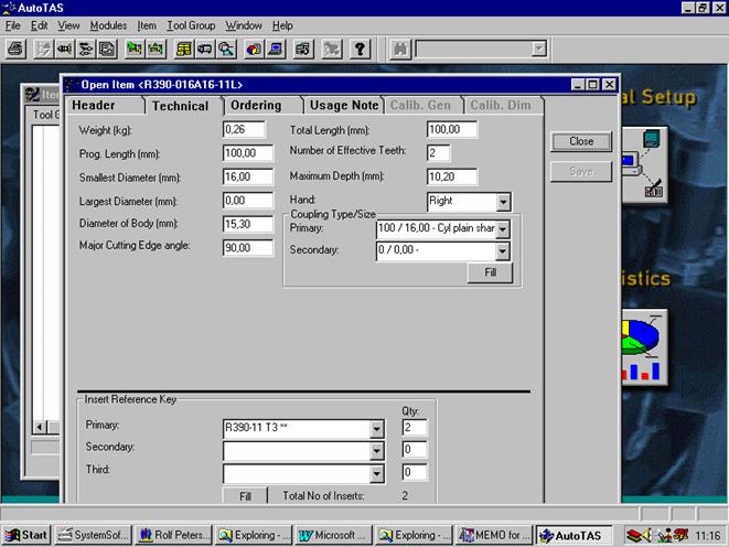
Illustration: Programming length is used when calculating the total length of a tool assembly.
All item drawings must have the machine coupling defined.
This is made in:
CPm Connection in
the machine direction.
CLm Centreline
in the machine direction.
The point CPm is the connection point for the previous item.
The line CLm is the centreline and direction of the drawing.
E.g. If the drawing is horizontal the centreline is also horizontal and if it is vertical the centreline is vertical.
AutoTAS automatically orients the item in a correct way when creating the assembly drawing.
Every drawing only has one connection point CPm and one Centreline CLm.
The point should always be on the centreline.
We recommend that the CPM is the zero point (0,0,0) on the drawing.
The following elements are defined in AutoCAD:
CPm: Entity type: POINT
Layer: TDLCtrM
Position: 0.0 0.0 0.0
CLm: Entity type: LINE or LINE
Layer TDLCtrM TDLCtrM
From: Xf 0.0 0.0 0.0 Yf 0.0
To: Xt 0.0 0.0 0.0 Yt 0.0
Important! The direction of the connection line should be
defined in the direction from the cutting side to the machine side.
Example
The centreline Clm for this drill is defined in the direction from the cutting side to the machine side. In this case the drawing will automatically be rotated 180 degrees, as tool assemblies always are displayed from left to right in AutoTAS
Addition
to the machine side every item requires a connection in the cutting part
direction:
CPt1 for holder/adapters (Basic Hoders, Adapters, Extensions) this point is the connection point for the next item.
For cutting tools (Drills, Milling cutters, Turning tools etc.) this point defines the cutting edge.
CLt1 for basic holders (Holders, Adapters, Extensions) this line defines the centreline. for the next item.
For cutting tools this line is not necessary.
Every drawing must have on connection point CPt1. For hoders/adapters also require the centreline CLt1. Both elements are defined the TDLCtrT1 layer. The point must be on the line.
The elements are defined in AutoCAD in the following way:
CPt1: Entity type: POINT
Layer: TDLCtrT1
Position: Xp Yp 0.0
CLt1: Entity type: LINE or LINE
Layer: TDLCtrT1 TDLCtrT1
From: Xf Yp 0.0 Xp Yf 0.0
To: Xt Yp 0.0 Xp Yt 0.0
For insert carriers the insert is included must be included in the drawing i.e. no drawings are required for the inserts. This of course means that the geometry and the nose radius not are displayed in the exact way.
Important! The direction of the connection line should be defined
in the direction from the machine side to the cutting side.
The left connection line in the layer CTR TDLCtrM (machine side) is defined from left to right. The left connection line in the layer TDLCtrT1 (tool side) is also defined from left to right.
For tools it is possible to define a second connection point and centreline.
This is made in the elements:
CPt2 2. Connection point on the cutting side
CLt2 2. Centreline on the cutting side
These elements are defined in the TDLCtrT2 layer.
The connection point must be defined on the line.
The second point should
be used for tools with two cutting part like boring tools
(e.g. R391.B0-R.) Otherwise these elements are empty!
Some additional information is required for different tool types.
|
Clm |
The centre line CLm must be in the TDLCtrM layer.
Both connection point CPm (machine side) and CPt (cutting side) must be on the line.
|
|
|
|
The additional items are not on the same centreline
as the basic holder. In this case the centreline CLt
is required together with the connection point CPt
CPt must be on the centre line.
Both are defined in TDLCtrT1 layer.
Additional items are rotated and on another centreline.
In this case the connection line CLt is required.
|
|
In this boring tools two cutting heads are defined.
One head should be displayed from the front side and the other from the backside.
In this case AutoTAS requires a second and a third
centreline through the connection points CPt-1 and CPt-2 .
Different cutting heads can also be defined.
Example Point CPt-1: R391.B02R-2012 - Front side +90 rotated
Point CPt-2: R391.B01R-2515 - Back side -90 rotated
 4.5
Examples
4.5
Examples
For some tools it is necessary to display both the front and backside.
Example:
Boring tool R391.B02R-2012 can be displayed in both ways depending how it is mounted in the assembly.
Both sides can be defined in one drawing. However, every side must be defined in a block, named with 'FRONT'(Front side) and 'BACK' (Backside)
The centreline and the connection points CPm and CPt must be defined in both blocks.
The connection point on the machine side CPm, for the front side should be placed on the
(0,0,0) zero point.
Some tools like boring tools have a range instead of a fixed connection point.
(Example: The boring tool R391.B0-R-40 D 053, has a range between 250 and - 350 mm)
In this case the connection point in direction cutting tool divided in 2 Points
CPtxin smallest Diameter
CPtx
a CPtxax largest Diameter
The range can be defined for the X or the Y-axis.
The actual value will be transferred from AutoTAS as a parameter.
4 connection points can be defined for boring tools with two cutting heads.
Cpt1in-Cptax and CPt2in-CPt2ax. A centre line CLtx is required
The connection point Cptxax must be on the CLtx line.
All new drawing that are created manually or imported from DXF or IGES, should be based on the master drawing SANDVIK.DWG.
In the master drawing are the following entities:
the 12 AutoTAS layers
Dimensioning type 'SANDVIK_DIM'
Font 'SANDVIK_STYLE'
Point type
To render a correct usage of the tool drawings in AutoTAS the minimum is the layers TDLCtrM, TDLCtrT1 and in addition layer, e.g. TDLConAlw required.
The following should be considered, dimensioning lines CLx should have the property 'Thin", otherwise the representation would be incorrect, as all thicker lines are made up by 4 lines in a corner of the contour. As the first line is perpendicular to the centreline the part will be assembled rotated by 90 degrees!
When importing dimensioned DXF drawings then the dimensioning lines will not be imported unless you ungroup the lines and texts.
AutoTAS can only work with Version 12 DXF. There are representation problems dimensioning arrow have to be ungrouped.
There should be only single entities like lines, poly lines, circle, circle segments and text strings.
When starting AutoCAD the start drawing should be Sandvik.DWG then are all necessary information about Layers and text definitions per AutoTAS available.
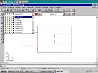
Then you select layer
TDLConAlw and draw the main contour.
Then select layer TDLConCmp and draw the hidden contour, coupling related contour etc.
The colour for each layer should be selected per specification.
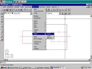
The next step is to draw the centrelines CLm and CLt and the connection point CPm and CPt in the corresponding layer. For that you select the functions 'Draw-Line" and 'Draw-point".
Finally make the dimensioning, note that the dimensioning have to be ungrouped. (Dimensioning in AutoCAD LT does not follow the standard from DXF Version 12!)
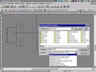
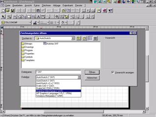
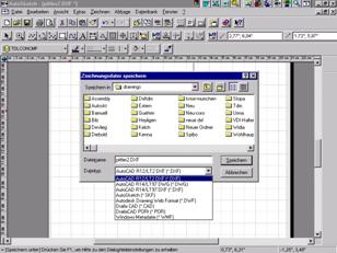
When the drawing is
completed, save it as AutoCAD drawing (.DWG) and with the command
'Create-DXF" generate the DXF data. This DXF-drawing should be stored in
the folder given in AutoTAS (e.g. C: AUTOTASDRAWINGS)
AutoSketch 5 -
Store the DXF drawing AutoCAD LT -
Store the DXF drawing
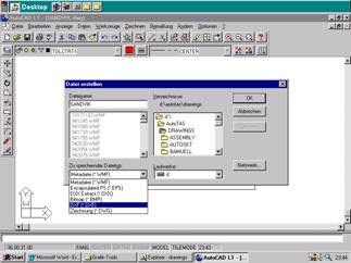
To be used in AutoTAS the drawings have to be stored in DXF Format. Drawing names referenced AutoTAS 3.2 and 3.21 can have maximum 8 characters plus the extension '. dxf". This is the normal 16-bit environment limitation.
It is possible to include the path in the drawing reference in AutoTAS in the field for drawing numbers, e.g. c:autotasdrawingsdxfxyz.dxf
The limitation using this method is that all drawing references for each product has to be edited if the folder with drawings is moved. It is better to keep all drawings in the default directory given in AutoTAS, the only one change needed to get all drawing is in the AutoTAS 'General Setup' of drawing path.
Hint : In AutoSketch 2.0 can the DXF drawing not be saved directly in DXF format, it has to be 'Exported'.
To use existing drawing, own or from tool suppliers, have to be modified to the AutoTAS standard before they can be used.
DWG - Files - load, modify and export to DXF Version 12
If
the drawing are drawn with the corresponding layers, the layers can be renamed.
Then select menu 'Data/Layer' as per below illustrations.
AutoCAD LT -
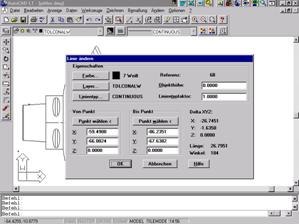
Rename layer, colour, and line type AutoCAD LT -
Layers
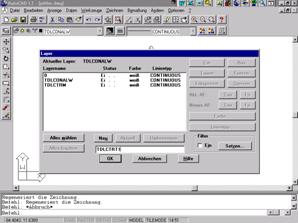
Here you can (Sample TDLCTRT1) make a new or rename existing, select from list, give a new name and press Rename. Corresponding actions can be made for Text, Line type and Dimensioning.
Existing entities can be moved and modified per illustration above right.
When ready save the drawing and export to DXF format.
DXF - Files are drawings in exchange format that can be imported directly.
First load the master drawing SANDVIK.DWG laden, then load existing drawing. Add the required connection points for AutoTAS.
You can load the DXF drawings directly but the layer information is missing so that has to be defined.
You can load an empty master DXF, then the DXF drawing and move and rename the entities.
The following information must be given:
Contour visible when assembled should be found in the layer TDLConAlw , hidden contour when assembled should be found in the layer TDLConCmp
Connection point on the machine side should be found in the layer TDLCTRM
Connection point on the cutting tool side should be found in the layer TDLCTRT1
Additional information can be added like dimensioning in layer TDLMeaAlw or TDLMeaCmp, Text, orientation lines in the layers TDLCTRM and TDLCTRT1
Note: When defining an insert cutting point no orientation line is required in layer TDLCTRT1 only point is required.
AutoTAS allow the usage of draw bolts when building assemblies. The connection point is the zero point for the basic holder E.g. the connection point for the cutting tool side Cpt1 is defined that the Cpm of the basic holder. See sample in Chapter 4.4
There might be differences in the way tool manufacturers define the connection points for tools. When mounted in a chuck the shank rear end is the reference point could be the connection point, then the chuck should have the deepest insertion point as reference. Then it is important that the shank is divided in two parts one drawn in layer TDLCONALW and the other in layer TDLCONCMP divided where the maximum clamping length is.
For AutoSketch there should be a master drawing named AutoTAS.SKT, here should all the properties be defined
For modification of existing drawings in AutoSketch you can load DXF part directly.
After opening the master drawing load the desired drawing.
For information on the entities, open 'Properties'.
Illustration: Information about Graphics Illustration: Change properties for
entities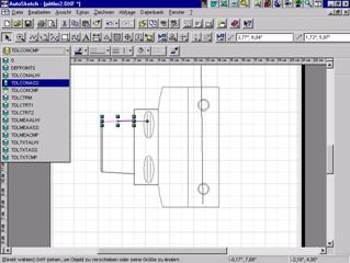
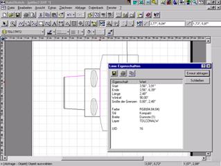
You can mark an entity on the drawing with the mouse find and change the properties and assignment to layers etc. Please note that AutoTAS up to and including Version 3.21 require AutoCAD version 12!!
Abbildung Zeichnung/DXF speichern
Illustration to Create and Store DXF drawing
With these program versions you can work in an analogue way. Please note that for centre lines on layers TDLCTRM and TDLCTRT1 line width should be 'Thin', otherwise the rotation of the part at assembly will be rotated 90 degrees!
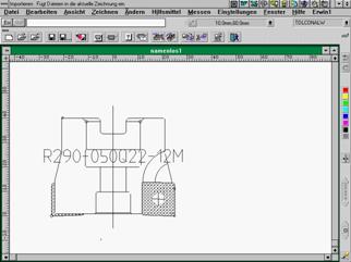
AutoSketch 2.0 - Illustration
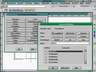
AutoSketch - Change of layer name
Ingenieurschule St. Gallen, Schweiz, has developed a defacto Standard for CAD drawings. This standard has been accepted by CIMSource, Standard OpenBase GbR mbH and all Standard Openbase members. AutoTAS Version 4.0 requires this format.
Both layer names can be used but Coromant DXF drawings use the numeric layer names.
|
Layer name |
Optional Layer no |
AutoTAS-Layer |
Type |
Sta- tus |
Colour |
Content |
Comment |
|
Con-tinous |
On |
White |
The Layer 0 reserved for AutoCAD- System, it cannot be deleted nor renamed. Not used with AutoTAS. Status is normally 'off" | ||||
|
TDLCONALW |
Con-tinous |
On |
Cyan |
Contour |
Holds all contour |
||
|
SK1 |
TDLCONCMP |
Con-tinous |
On |
Cyan |
Contour of single items |
The parts of the contour that is not visible when assembled |
|
|
TDLMEAASS |
Con-tinous |
On |
White |
Dimensioning for single items and assembled milling and drilling tools | |||
|
2L |
TDLMEAASS |
Con-tinous |
On |
White |
Dimensioning for single items and assembled turning tools | ||
|
SK2 |
TDLMEACMP |
Con-tinous |
On |
White |
Dimensioning single item |
Holds all dimensioning that is not visible when assembled |
|
|
TDLCONASS |
Hidden |
On |
Red |
Additional entities to describe assembled tools |
Required entities that describe assembled tools. |
||
|
SK3 |
Hidden |
On |
Red |
Additional items to describe single items |
Required entities that describe single items that are not visible when assembled. |
||
|
Centre line |
Off |
Yellow |
Centre line for assembled tools | ||||
|
SK4 |
TDLCTRM |
Centre line |
On |
Yellow |
Centre line for single items | ||
|
Con-tinous |
Off |
White |
Reserved for the user for form and texts in forms |
Reserved layers are also 51-59 |
|||
|
Con-tinous |
On |
Blue |
Text for assembled tools and insert shading |
Just insert shading if the reserved layers 61-69 are used for other languages |
|||
|
SK6 |
TDLTXTCMP |
Con-tinous |
On |
Blue |
Text for single items that is not visible when assembled |
10.2.1 Additional layers (Optional)
There are provisions for defining the cutting contour and use of multiple language descriptions. These are optional layers for such information.
To use the CAD drawing for simulation of the cutting process it is necessary to differentiate between the cutting part (layer 15) and the holder portion (layer 1) of the tools. Contact between holder and the work piece constitutes a collision. For rotating products the cutting contour can be created by rotation of the insert contour.
|
Layer name |
Layer number |
AutoTAS-Layer |
Type |
Status |
Colour |
Content |
Comments |
|
Con-tinous |
Off |
Rot |
Cutting contour | ||||
|
Con-tinous |
Off |
White |
Lines in form | ||||
|
Con-tinous |
On |
White |
Text in form, German | ||||
|
Con-tinous |
Off |
White |
Text in form, English | ||||
|
Con-tinous |
Off |
White |
Text in form, French | ||||
|
Con-tinous |
off |
White |
Texts reserved for other languages | ||||
|
Con-tinous |
On |
Blue |
Text assembled product, German | ||||
|
Con-tinous |
Off |
Blue |
Text assembled product, English | ||||
|
Con-tinous |
Off |
Blue |
Text assembled product, French | ||||
|
Con-tinous |
off |
Blue |
Reserved for other languages | ||||
|
Con-tinous |
On |
Blue |
Analogue to Layer 61 etc. single items | ||||
|
TDLCTRM |
Centre line |
Off |
Yellow |
Connection point on the machine side defined by a centreline and a point (0,0) | |||
|
TDLCTRT1 |
Centre line |
Off |
Yellow |
First connection point on the cutting side defined by a centreline and a point | |||
|
TDLCTRT2 |
Centre line |
Off |
Yellow |
Second connection point on the cutting side defined by a centreline and a point | |||
|
Manufacturer specific information |
When creating CAD drawings there are certain prerequisites so that assembled tool can be automatically assembled and presented in an orderly fashion. The most important issues are:
Uniform layer structure per specification
The contour has to be drawn in scale 1:1
The connection points and centre lines properly defined
Correct dimensioning
For each item one reference point has to be given that later could be used for building assemblies. The reference point on the machine side should be identical to the drawing zero point (0,0). The machine side reference point is the insertion reference point relative to the preceding component.
Connection points found in layer 80 (machine side), 81 (ditto cutting side) and 82 (ditto cutting side second point) always given by a point and centre line, see illustration below.
|
Connection point machine side (left) |
Connection point (right) |
|
(Connection point to the previous component) Point (0,0) and centre line in layer 80 |
(Connection point for next component to the right Point and centre line in layer 81 |
|
Contour for the hidden coupling parts in layer 11; visible only as single item |
Contour in layer 1 Visible in all cases |
Rules for the drawing data in DXF files
For the single item drawings:
The zero point is determined as the intersection of the centre line and the left contour visible for tool assemblies (Layer 1).
The tool length and the collision diameters for the individual components should be given in the tool assembly.
Form definition and texts should be given in the separate layers. (Layer 5 or 50-59)
Rules for dimensioning of individual items in DXF files
The components in an assembly should be dimensioned per below:
The distance from the zero point to the cutting point should be given.
All single item functional dimensions should be given.
In the case that the cutting diameter isn't the largest diameter, the largest collision diameter should be given.
Rules for the dimensioning of assembled tools
To get a uniform presentation the following conditions should be met:
All dimensioning of assemblies concerning milling or drilling tools should be given on Layer 2.
All dimensioning of assemblies concerning turning tools should be given on Layer 2L.
Dimensioning information for single items (all types, milling, drilling and turning tools) to be given on Layer SK2 (12)
The distance from X1 dimension and the component centre line, for components with diameter < 125 mm should be fixed 75 mm. For component with diameter >= 125 mm the diameter value should be located 25 mm above the largest contour diameter.
All length dimensions should be incremented by 15 mm under the X1 dimension.
The parameters for texts and dimensions should be set at:
Angle:
0 degree
Height: 4,57 mm
Font: Simplex
The adaptation of layer structure is possible in a number of ways. First, the procedures laid out in the sections 7, 8 and 9. Secondly, there is a software that will make a batch conversion of selected drawings in one directory to another.
Conversion from AutoTAS to ISG format can be done using the software named AT2ISG.EXE. Start the software and select a Source Directory and a Target Directory, then Select -> the drawings to convert.
With the Select ALL >> will all drawings in the source directory be selected for conversion. With the command <-- Remove or <== Remove can highlighted or all drawing be deselected.
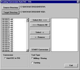
Start Conversion will start the conversion.
Note! There are different cases like Milling/Boring and Turning valid for the respective type of products.
As the conversion progresses each converted drawing is marked with an okay in the right list box.
When the conversion is completed, use the Exit button.
Table of Content:
1. General
2. Layer Structure
3. Definition of Text
4. Drawings for Tool Assemblies
4.1. Connection the machine side
4.2. Connection on the tool side
4.3. Second connection point on the tool side
4.4 Rules for different tool types
4.5 Examples
5. Special Cases
6. Instructions for creation of drawings.
6.1. Master drawing
6.2. Layers
6.3 To work with AutoSketch 2.0
6.4. To work with AutoCAD, AutoCAD LT
7. Samples of drawings created with AutoCAD LT
8. Working with AutoSketch Version 5
9. Working with AutoSketch 2.0 and 2.1
10. The neutral format for DXF drawings per ISG Standard
10.1 The ISG Standard
10.2 Layers
10.2.2 Structure of drawings
11. Conversion of CAD drawings
|
Politica de confidentialitate | Termeni si conditii de utilizare |

Vizualizari: 3031
Importanta: ![]()
Termeni si conditii de utilizare | Contact
© SCRIGROUP 2024 . All rights reserved