| CATEGORII DOCUMENTE |
| Asp | Autocad | C | Dot net | Excel | Fox pro | Html | Java |
| Linux | Mathcad | Photoshop | Php | Sql | Visual studio | Windows | Xml |
The design and development of distributed systems is more complex now than ever. Architects need new ways of reducing this complexity to increase the predictability of deployment. To do this, they must find new techniques for diagramming these systems by using rich metadata about both the design and the deployment's operational requirements.
How many times has the IT operations team locked down the servers or implemented restrictive group policies that lessened the application's chance of deployment? What usually ends up happening? The result is compromise during crunch time-which isn't good. On the other end of the spectrum, the IT group could inundate the developers with paperwork or meetings, outlining every service pack, version, and configuration of their datacenter. This, too, is counterproductive. What the developers want to know is whether SQL Server will work and whether their ASP.NET Web services will be able to access it.
The best solution is to have solution architects communicate their designs effectively to the IT operations team and to have infrastructure architects and operations communicate information about their hosting environments back to the developer side of the house.
One thing is clear; architects' needs are different from the needs of project managers. Architects have a need for solid design tools that can easily generate code or classes. These tools are provided solely by Visual Studio 2005 Team Edition for Architects. Using these tools, architects can create one of the following Distributed Application Diagrams (DAD):

Application diagrams
Logical Datacenter diagrams
Deployment diagrams
System diagrams
These diagrams, like any good model, tell a story to other team members, who might not share the same level of expertise as the architect. Communication to other members of the team, as well as to non-technical stakeholders of a project, is important, and pictures improve the chances of effective communication taking place. This communication can lead to better collaboration. For example, if a team's architect can accurately diagram the network infrastructure and then demonstrate how the project's application will deploy successfully onto the servers, some of the operational staff's worries can be alleviated.
A major new initiative by Microsoft and other industry partners, is the Dynamic Systems Initiative (DSI). The goal of DSI is to reduce complexity while increasing communication flow. It provides a was to design for the eventuality of the software being deployed, to design for operations. A key feature of DSI is providing visualization of systems and services and tracking the metadata about each to properly describe it to another system or service. This metadata will allow for one diagram to validate against another, and an important solution for architects to validate their application design against an infrastructure architect's datacenter design.
DSI is geared toward ensuring that the design is correct the first time and that it will deploy into the host environment successfully. But it's more than that-DSI also aims to capture knowledge and lessons learned once an application gets deployed and to apply that knowledge for easier ongoing maintenance. To achieve this, new techniques are needed for describing systems using rich metadata about both the design, development, deployment, and operational requirements that can be understood and exchanged by various automation tools.
Domain experts in various software development areas will need to brainstorm and capture all the important metadata about a particular component. This metadata includes settings, constraints, versions, modes, security-in short, everything. Think of the effort as creating a schema to describe every type of operating system, application server, and Web server, as well as every major type of application or service that can be built with .NET. All these DSI models need to be boiled down to common terms or interfaces so that the settings of a .NET Web Service can be validated against the policy restriction on the deployment side, for example. As more systems can be fully described using the DSI approach, many more possibilities emerge for building true automation into the entire software development life cycle.
Microsoft's first development DSI offering will surface in Visual Studio 2005 Team System. The implementation of this offering will be known as the System Definition Model (SDM). SDM classifies the application and its deployment environment in layers, much the same way that the Open System Interconnection (OSI) model describes a network stack. SDM defines the following layers (from the top down):
Application
Application Hosting
Logical Machines and Network Topology
Hardware
Visual Studio's SDM integration will continue to improve as we move into Visual Studio Codename Orcas, which is the next version of Visual Studio. However, the SDM platform also applies to Windows directly, especially going forward into Windows codename Longhorn. This maturing SDM platform will facilitate the design, deployment, and ongoing operations of systems in Windows, not just Visual Studio. Critical to this success is for each product team to build an adapter that other teams will depend on for design-time validation. The obvious integrated applications here will be Systems Management Server (SMS) and Microsoft Operations Manager (MOM), which could both leverage SDM to make integrators' and administrators' jobs easier.
 Domain-Specific Languages
With VSTS, Microsoft takes a model-driven approach to software development
which could be referred to as visual engineering. Microsoft, as well as many others
in the industry, feel that Unified Modelling Language (UML) tools can take the
process only so far. UML-class diagrams, for example, don't
Microsoft still provides key support for UML via Visio, including creating the popular use-case and sequence diagrams.
Here is an example of how users might use Visio in their VSTS environment:
Launch Visio Professional 2003.
Create use-case, sequence, and other UML diagrams.
Create class diagrams using UML notation.
From
Visio, generate C# or Microsoft Visual Basic .NET code from the class diagrams
created.
Add the code files generated to the Visual Studio 2005 project.
Open a class in the Class Designer (which is a new DSL tool).
Fine-tune the class for .NET.
The DSL tools in VSTS include the Class Designer and the Distributed System Designers and their common features, such as continuous synchronization and a design-first approach that's tied together by SDM.
Network and other topology diagrams have historically been of little value to developers or a development effort. In keeping with the principles of SDM, the Logical Datacenter Designer will allow network/infrastructure architects to create diagrams of their deployment environments that are more than just pretty pictures. The diagrams will have schema, including constraint metadata that will allow solution architects to test-deploy their applications. These diagrams are an abstraction of the physical environment, hence the term logical. The servers that the architect drags and drops will represent server roles in an actual deployment, so any constraints and settings placed on these servers should be general.
Logical datacenter diagrams can contain the following logical servers:
Windows Client
A rich .NET Windows client
IISWebServer
An Internet Information Server (IIS) that can run an ASP.NET Web application or service
DatabaseServer
A SQL server
GenericServer
Any other server, such as Microsoft BizTalk, COM+, MSMQ, Exchange, or another, non-Microsoft server
These logical servers can be placed in zones. A zone is defined by a boundary, such as a firewall, cluster, domain, or other security boundary. Zones are a easy way to place servers in a logical group. Zones can also have metadata and constraints. Figure 3-2 shows logical servers placed into zones.
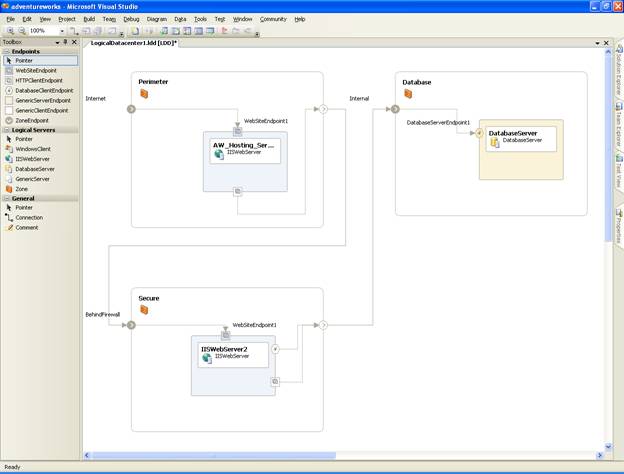
Figure 3-2
Logical servers grouped into zones
After dragging and dropping zones and servers and arranging them appropriately, infrastructure architects will want to set the appropriate settings and constraints. This will ensure that only the correct type of service, version, and security are allowed onto each of their boxes. This process is a way for infrastructure architects to define the policies of their datacenter.
This documentation will become evident when a deployment report is generated. More importantly, these settings and constraints are required to implement SDM. Solution architects can see right away what the requirements and restrictions are for their software.
Here are some examples of types of settings and constraints:
Zone Constraints.
This type of constraint defines the following characteristics:
The type of logical server that can exist within the zone
Versions of .NET runtime that can exist on the servers within the zone
Whether
or not there is support for the global assembly cache (GAC) on the servers
within the zone
IIS settings, such as application-pool restrictions on the servers within the zone
Whether or not the zone can contain other zones
Windows Client Constraints.
This type of constraint defines the following characteristics:
Whether or not the client can run Office applications
Whether or not the client can run other generic or Windows applications
Windows Client Settings.
These settings define the following characteristics:
Operating system type, version, build, and service pack (See Figure 3-3.)
Application name and path
Version of the .NET runtime
Whether or not there is a need for the GAC
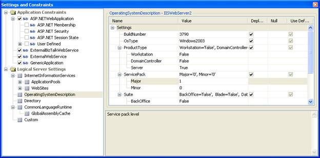
Figure 3-3
Configuring operating system settings
IIS Web Server Constraints.
This type of constraint defines the following characteristics:
The type of application (ASP.NET, BizTalk, external Web application, or other generic application)
Whether or not the ASP.NET application requires membership support and related settings
The type of ASP.NET security (none, forms, Passport, or Windows) and related settings
The type of ASP.NET session state (off, in-process, state server, SQL server, or custom) and related settings
Other ASP.NET Web server settings the target application must specify in order to run on this server
IIS Web Server Settings.
These settings define the following characteristics
IIS server settings, including application pools, Web sites, and their endpoints
Operating system type, version, build,
and service pack
Application name and path
Version of the .NET runtime
Whether or not there is a need for the GAC
Database Server and Generic Server Constraints.
This type of constraint defines the following characteristics:
The type of application that can be installed on this logical server (external database or generic application)
Each server type and zone shape allows specific custom settings so that organizations can track any additional metadata. Figure 3-4 shows an example of a custom setting for a zone, which specifies that each server placed in the zone must pass the Baseline Security Analyzer test. This test is a security diagnostics utility that tests the integrity and security best practices of many Microsoft servers applications.
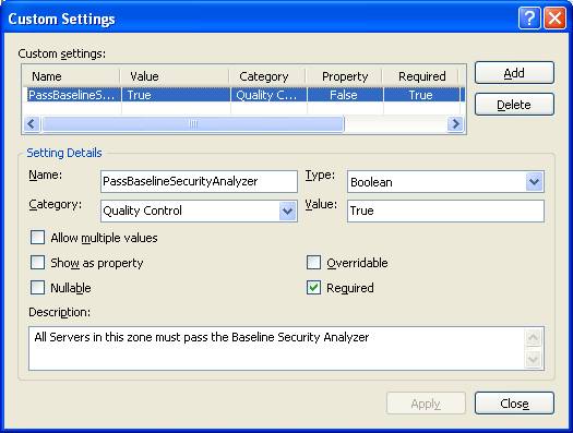
Figure 3-4
Creating a custom setting
The final step in designing logical datacenters is to connect the endpoints of the various shapes: zones to zones, servers to servers, and servers to zones. These endpoints can be thought of as being physical ports or communication pathways. These connections convey a workflow of information. They also form another constraint check: consumer endpoints have to match provider endpoints for the connection to be allowed. This requirement will keep organizations from connecting to their database server over port 80 as an HTTP consumer when they really need to connect as a Tabular Data Stream (TDS) consumer.
Solution architects are accustomed to walking up to a whiteboard and diagramming their application. Their diagram usually consists of some squares, some text, and some lines connecting them. If these doodlers are lucky, the whiteboard has the ability to e-mail or print the drawing for later reference. Or maybe someone nearby has a digital camera. The VSTS Application Designer provides an intelligent whiteboard, which allows the architect to drag and drop services and applications onto the design surface, configure settings, and then connect the shapes.
The Application Designer is superior to the whiteboard and modeling applications such as Visio in several areas:
It's a permanent, updateable, source-controlled document part of the team project.
It can be test-deployed against one or more logical datacenters, with validation.
It can generate code for the developers to begin implementing the services.
It can generate a deployment report for the IT operations team.
It can be saved to the toolbox or as individual systems for reuse in later diagrams.
It is easy to understand (See Figure 3-5.)
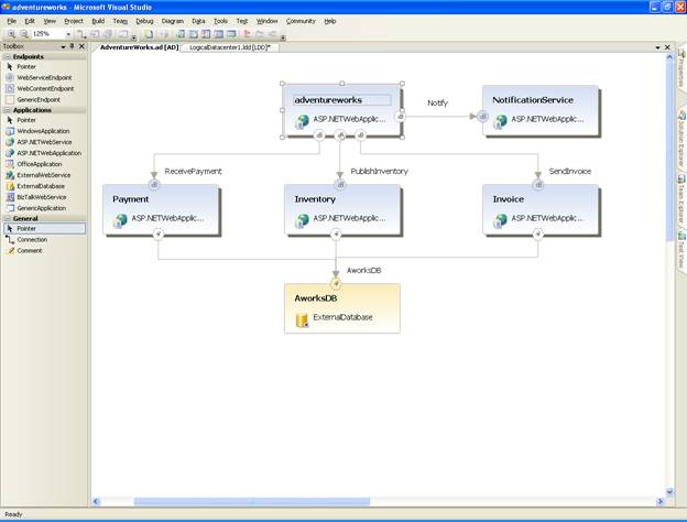
Figure 3-5
A sample application diagram
Application diagrams can contain the following application and service types:
WindowsApplication
A .NET Windows forms application
ASP.NETWebService
An ASP.NET XML Web service
ASP.NETWebApplication
An ASP.NET Web forms application
OfficeApplication
A Visual Studio Tools for Office (VSTO) application
ExternalWebService
A non-ASP.NET Web service (a Web Services Description Language document)
ExternalDatabase
Any database or database server
BizTalkWebService
A BizTalk orchestration exposed as a Web service
GenericApplication
Any other application that isn't already mentioned in this list
After the diagram is built, the solution architect needs to set the appropriate settings and constraints on their applications and services. This will document and communicate any special requirements to VSTS. This documentation will also surface when a deployment report is generated. More importantly, these settings are used during the test deployment to validate the application design against a predefined logical datacenter diagram.
For example, if the solution architect defines an ASP.NET Web Service that requires version 2.0 of the .NET Framework, this service won't deploy to a server that the infrastructure architect defined to support only version 1.1. When the deployment is validated, this conflict will surface as a validation error and a resolution will be required.
Similar to logical datacenter diagrams, the final step in creating application diagrams is to connect the shapes: applications to services and services to services. These communication pathways are akin to the lines that are drawn on a whiteboard, connecting squares. As with logical datacenters, these lines convey a communication workflow to the casual observer, but they also document the connectivity requirements of the application. During the test deployment, the success or failure will depend on whether these shapes are still able to communicate with each other within a particular datacenter.
An architect can use the deployment designer to test a deployment of an application diagram against a logical datacenter diagram. The two diagrams have to mesh correctly-the settings of the application diagram applications and services have to mesh with the constraints of the logical datacenter diagram, and vice versa.
Once the two diagrams have been completed, one of the architects, most likely the solution architect, will define a test deployment and carry out the validation. Both diagrams will need to be in the same project at this point, and checked out of source control.
The Deployment Designer allows an architect to drag and drop the various applications and services, as defined in the application diagram, onto the various servers in the various zones, as defined in the logical datacenter diagram. The applications and services can be found in the floating or dockable System View window. (See Figure 3-6.) It really is that easy-drag and drop until all the shapes are bound. If the mouse pointer changes to the "no drop" shape, which is the familiar circle with a line through it, users are not allowed to drop that application or service onto that server.
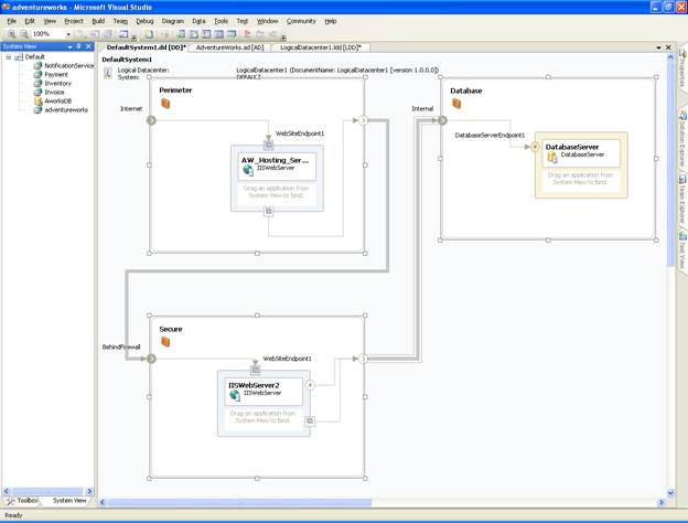
Figure 3-6
The System View window, which lists all applications and services
After all the applications and services are bound, the final step will be to validate the diagram. If any errors are detected, they'll be listed in the Errors List window, typically at the bottom center of the Visual Studio 2005 integrated development environment (IDE).
Once the validation succeeds, a deployment report can be generated that will serve as a bill of materials to deploy the application.
System DesignerThe System Designer can be used to compose and configure pieces and parts of an application diagram into systems. A system is considered a unit of deployment and is a configuration of one or more applications and other subsystems. By combining complex applications into a system, it is easier to handle large-scale distributed system scenarios. An application architect can design a complex multitiered system as a hierarchy of "nested" systems.
Creating a system diagram allows for more granular deployment, defined independently of the entire configuration shown on the application diagram. In some cases, the settings defined on the application diagram as a whole, can be overridden on the same application within a system diagram. In other words, multiple system definitions can be created, each having distinct configurations of the applications defined in the solution. This versatility allows different configurations to be defined for different deployments and perhaps for different logical datacenter configurations.
|
Politica de confidentialitate | Termeni si conditii de utilizare |

Vizualizari: 988
Importanta: ![]()
Termeni si conditii de utilizare | Contact
© SCRIGROUP 2024 . All rights reserved