| CATEGORII DOCUMENTE |
| Bulgara | Ceha slovaca | Croata | Engleza | Estona | Finlandeza | Franceza |
| Germana | Italiana | Letona | Lituaniana | Maghiara | Olandeza | Poloneza |
| Sarba | Slovena | Spaniola | Suedeza | Turca | Ucraineana |
CAS200 REF
CB - S&T
Ver. 3.7
Users Manual
INDEX
|
Page |
|||
|
General |
Preface | ||
|
A |
System requirements | ||
|
B |
Installation | ||
|
C |
Getting started | ||
|
D |
Starting-up CAS200 REF | ||
|
E |
Special settings | ||
|
CB units |
How to do a calculation for CB Units | ||
|
1.1 |
Rating Standard units | ||
|
1.2 |
Rating Special units | ||
|
1.3 |
Design Standard units | ||
|
1.4 |
Design Special units | ||
|
Printouts | |||
|
Appendix A |
CB Design Considerations | ||
|
A.1 |
General warnings about release 3.7 | ||
|
A.2 |
Pre-set applications | ||
|
A.3 |
Warnings in pop-up screens | ||
|
Appendix B |
Examples of printouts | ||
|
S&T units |
S&T applications | ||
|
S&T Evaporator | |||
|
S&T Condenser | |||
|
Printouts | |||
|
Appendix C |
S&T Design Considerations | ||
|
Appendix D |
Examples of printouts |
PREFACE
This manual is aimed to anyone involved with the design of Alfa Laval brazed plate heat exchangers (BPHE) and Alfa Laval shell & tube heat exchangers (S&T) in refrigeration applications. It is intended as a guide to using the CAS200Ref program.
In writing the manual it has been assumed that the tender/operator has some prior experience of Alfa Laval heat exchangers.
A. System requirements
Pentium IBM-compatible PC
32 MB of system memory (64 MB recommended)
15 MB of free hard disc space
Windows 9x/NT/2000 (note: the program runs only on 32 bits environment)
Installation time : 1 to 5 minutes
B. Installation
Our installation procedure is made in accordance to all normal Windows programs.
1. Start Windows
2. Put the first diskette into your floppy drive
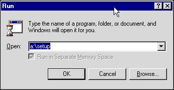
3. From Windows Explorer choose File and then Run. Type A:setup and click <OK>
4. Follow the instructions given on your screen, and answer the questions. The computer will give you suggestions (NOTE: the installation folder must be max 8 characters).
C. Getting started
Before you start calculating with CAS200Ref, please read carefully Appendix A for CB units and Appendix C for S&T units.
D. Starting-up CAS 200REF
After double clicking on the associated icon, CAS 200Ref will look like this :
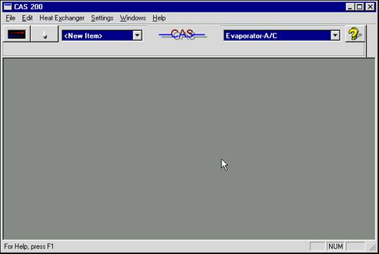
You should have version 3.7 (go to Help/About CAS200). All of the functions of the program can be operated using either the pull down menus or the shortcut buttons on the toolbar.
Once you have got used to them, you will find that they are easy to use.
On the left side of the toolbar you will find two buttons corresponding to the main modules of the CAS200Ref program.
![]()
The duty and design button is used to start with a new item.
![]()
The fluid editor button can be used when you want to edit the physical properties of fluids. You can display, add or remove fluids, or modify an existing fluid.
For on-line help you have only to press the F1 key (help is not available for S&T applications)

The shown list box gives you the possibility either to open an existing item or to create a new one (by selecting <New Item>). The naming of the saved items will be done at the time of exiting from the duty specification.
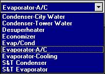
Before starting with a new item, you have to select an application from the application selection list box, in which youll find 7 preset applications for CB units and 2 preset applications for S&T units.
Each application has been pre-set with some input data, like water inlet and outlet temperatures, condensing temperature, evaporating temperature and so on. All of these data can be changed.
E. Special settings
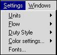
Once the
program has been started, it is important that the user should be able to
tailor the program to his requirements. Using the functions shown in the figure
below, the user can set up the program to suit his individual requirements.
Units :
Units to be used can be selected from the list : SI/S, SI/h, Metric, British, American or Japanese. Units can be changed at any time, also during a session.
Flow :
For 2 phase applications, you only have to enter flows as mass flows: the other option, volume flows, is not in effect.
Duty style :
Although you can make a choice between graphical and classic style, the graphical style will always pop up.
Color settings :
The colors that appear on your screen can be set using this command.
Fonts :
You can choose the font to be shown on the screen.
How to do a calculation for CB units
1. Pick out of the list of pre-set applications the proper application (e.g.: Condenser-Tower Water)
![]()
![]()
2. Open the duty/design module by clicking on the duty/design button
3. Enter the data by moving between input fields with the TAB-key (or by clicking on them)
(PRESSING THE ENTER BUTTON CAUSES TO BE PROMPTED FOR SAVING THE ITEM)
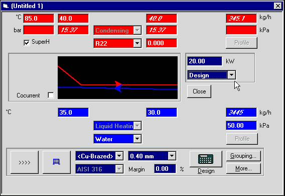
The above figure shows the pre-set values for the application Condenser-Tower Water, that is:
R22 superheated to 85 C condensing at 40C; outlet quality = 0
Water heated from 30 C to 35 C; max allowed pressure drop 50 kPa
There are two kinds of calculations to choose from:
T
 design: the duty is known; the
type of the BPHE and the number of plates are calculated.
design: the duty is known; the
type of the BPHE and the number of plates are calculated.
T rating: the design and duty are known; margins are to be calculated.
Moreover, you can choose to consider special units or standard units: in general, different applications will have different lists of special and standard units. Note that each application is pre-set for doing a design calculation of special units.
 So, you have
the following options:
So, you have
the following options:
Rating - standard units
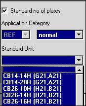
Click on the More button. A new window will come, named Thermal Configuration. Mark the check box Standard no of plates and choose normal in the list box named Category.
Choose the standard unit youre interested in from the listed standard units in the corresponding list box.
Click on the OK button to confirm your choice and go back to the duty/design window.
 Fill in the
remaining input fields (like capacity) and click on the Rating button (lower
right corner) to start calculation.
Fill in the
remaining input fields (like capacity) and click on the Rating button (lower
right corner) to start calculation.
Rating - special units
Make sure that the check box Standard no of plates is not marked (click on the More button to open the Thermal Configuration window and clear the check box Standard no of plates; click on the OK button to confirm your choice and come back to the duty/design window)
 Select the
special unit youre interested in from the list box (as an example, shown in
figure are the special units for the Condenser - Tower Water application)
Select the
special unit youre interested in from the list box (as an example, shown in
figure are the special units for the Condenser - Tower Water application)
Click on the Grouping button to input the design data (like number of passes, number of plates, type of plates, etc.). Click on the OK button to confirm your choice and come back to the duty/design window.
Fill in the remaining input fields (like capacity) and click on the Rating button to start calculation.
Design - standard units
Click on the More button to open the Thermal configuration window. Make sure that the check box Standard no of plates is marked and choose normal in the list box named Category. Then choose if you want to process standard units with or without distributor (to change the default setting, click on the check box DX Evaporator. Click on the OK button to confirm your choice and come back to the duty/design window).
You have two possibilities:
 1. if you want
to process only one unit, choose the unit youre interested in from the list
box shown in figure. Note that the calculation will be done only if the chosen
unit really belongs to the standard units associated with the application
youre using.
1. if you want
to process only one unit, choose the unit youre interested in from the list
box shown in figure. Note that the calculation will be done only if the chosen
unit really belongs to the standard units associated with the application
youre using.
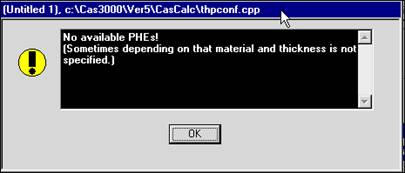
If this is not the case, the following warning will come:
Input a margin in the proper box, if needed.
 Fill in the
remaining input fields and click on the Design button (lower right corner) to
start calculation. The most efficient standard unit of the selected type will
be processed.
Fill in the
remaining input fields and click on the Design button (lower right corner) to
start calculation. The most efficient standard unit of the selected type will
be processed.
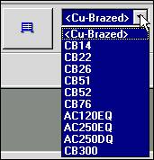
2. you can also do just one calculation for many types of standard units. Select <Cu-Brazed> in the list box for units selection. Note that the set of units associated with the item <Cu-brazed> changes with the plate thickness (see Appendix A for more details).
Generally speaking, if you have marked the check box DX Evaporator in the Thermal Configuration window, standard units with distributor (X and EQ) and CB14, CB22, CB26 will be processed.
If you havent, all Cu-brazed units will be considered except CB51X, CB52X, CB76X and CB300X.
![]()
Click on the button here shown to see which units will be processed.
That causes the PHE Selection window to be opened. It will look like this one:
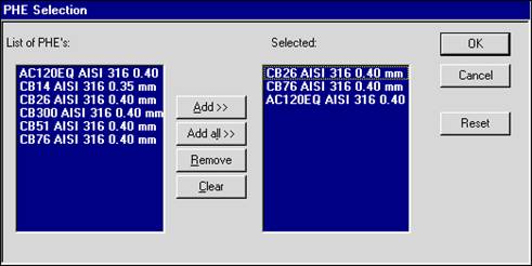
Depending on your choice about the check box DX Evaporator, different lists will appear. You can add/remove units as you like. Then, click on the OK button to come back to the duty/design window.
Input a margin in the proper box, if needed.
Fill in the remaining input fields and click on the Design button (lower right corner) to start calculation.
This way the program will process as many standard brazed heat exchangers as youve selected.
Design - special units
First of all make sure that the check box Standard no of plates is not marked. (click on the More button to open the Thermal Configuration window and check; click on the OK button to come back to the duty/design window).
As for standard units, you have two possibilities:
1. if you want to process only one unit, choose the unit youre interested in from the units selection list box.
Input a margin in the proper box, if needed.
Fill in the remaining input fields and click on the Design button (lower right corner) to start calculation.
2. if you want to process many different units, select <Cu-Brazed> in the list box for units selection. Note that the set of units associated with the item <Cu-brazed> changes with the plate thickness (see Appendix A for more details). Generally speaking, if you have marked the check box DX Evaporator in the Thermal Configuration window, standard units with distributor (X and EQ) and CB14, CB22, CB26 will be processed.
If you havent, all Cu-brazed units will be considered except CB51X, CB52X, CB76X and CB300X.
![]() If you want to
change the default units, clic on the button shown to open the PHE selection
window (see above).
If you want to
change the default units, clic on the button shown to open the PHE selection
window (see above).
Input a margin in the proper box, if needed.
Fill in the remaining input fields and click on the Design button (lower right corner) to start calculation.
If you do a calculation like that one indicated with number 2 above (design both for standard and special units), units will be ranked in the output window on the basis of a price indication factor.
Please note that the program always proposes you the cheapest solution. You have to remember that:
T the price indication factor is not updated with the actual price list
T the cheapest solution is not necessarily the best technical solution
The next figure shows the result of a design calculation for condensing standard units with a required capacity of 30 kW and an input margin of 0 %, obtained with the application Condenser-Tower Water.
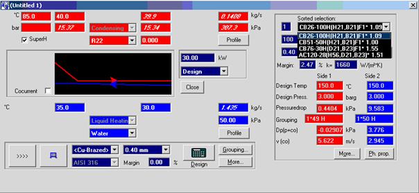
To save the item, press the Close button and give it the name.
Printouts
All printouts can be done using your Windows fonts and you can also add pictures to your prints (e.g. you can add your logotype and other pictures directly on your printout template). See Appendix B.
All printouts use some templates. These templates can be edited in your word processor. You can edit them yourself and add pictures and/or instructions. All templates use a script language called WRIX to give instructions about the layout and to select the proper parameters to be printed.
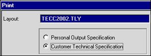
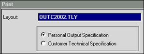
The default templates are indicated in the following figures:
Appendix A Design considerations
Here youll find some important considerations to be taken into account when you use the program for selecting CB units in the refrigeration field.
A.1 General warnings about release 3.7
A.1.1. You can do two types of calculations: design and rating. As a rule, you can switch between these two types in the same item. In Design calculations, the maximum pressure drops which have been set up (and that you can change) affect the results. A Rating calculation is done without any limitation on the pressure drops.
A.1.2. As default, each application has pre-set <Cu-brazed> and 0.4 mm for the plate thickness. This way the following units will not be processed: CB14 and CB22. To have them processed when you select <Cu-brazed>, choose <Minimum thickness> or 0.35 mm in the list box for the plate thickness and ignore the warning that will come.
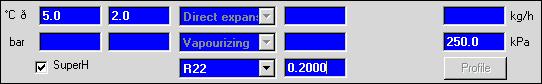
A.1.3. The following applications: Economizer, Evap/Cond,
Evaporator A/C and Evaporator Cooling have preset values for the condensing
temperature and the subcooling level. But
you can choose to enter instead the vapor inlet quality. Then, click on the
More button, then click on the Advanced button in the Thermal
configuration window. It will be opened another window, Extra input for
2-phase calculations: click on the check box Give inlet quality, and finally
click on the OK button until you come back to the duty window. The figure here
below shows the new input box for the inlet quality.
A.1.4. The CB applications Condenser-Tower Water and Condenser-City Water have fouling factor=0. To take account of not clean conditions, give a fouling factor > 0.
A.1.5. When you make a design calculation selecting Cu-brazed, AC250, AC80DQ and AC130DQ will not be considered. You must repeat your calculation explicitly selecting AC250, AC80 and AC130.
A.1.6. About AC80, AC130DQ and AC250DQ, note that:
a) number of plates must be even and not multiple of 4 (the real double circuit requires to have an equal number of refrigerant channels on circuit 1 and 2)
b) they cant be calculated in partial load condition
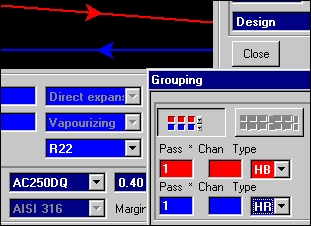
c) in design mode, the program selects the wrong type of channel plates leading to wrong pressure drop evaluation. The workaround is to press the button 'Grouping' and select the right channel type (HR on the refrigerant side, HB on the brine side) before making the calculation (picture below refers to an evaporating duty as an example)
d) the program defaults to 1 connection (in and out) on refrigerant side. Before making the calculation, press the 'More' button and enter 2 instead (in and out). Picture below refers to an evaporator, as an example.
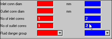
e) you must enter also the inlet and outlet conn. diameter on the refrigerant side:
AC250DQ 80 mm
AC130DQ 49 mm
AC80DQ 38 mm
A.2 Preset applications
The following tables show, for each application, the fluids (on both sides), the special units and the standard units you can choose from.
Application:
|
Refr |
Brine |
Special units |
Standard units |
|
all Rnnn |
water eth. glyc. prop. glyc. |
CB14 CB22 CB26 CB51 CB52 CB76 AC80DQ AC120EQ AC250EQ AC250DQ CB300 |
CB14 CB26 CB51 CB76 AC120EQ CB300M |
Application: Desuperheater
|
Refr |
Brine |
Special units |
Standard units |
|
all Rnnn |
water eth. glyc. prop. glyc. |
CB14 CB22 CB26 CB51 CB52 CB76 CB300 |
CB14 CB26 CB51 CB76 CB300M |
Application: Economizer & Evap/Cond
|
Refr |
Brine |
Special units |
Standard units |
|
all Rnnn |
all Rnnn |
CB14 CB22 CB26 CB51 CB51X CB52 CB52X CB76 CB76X AC80DQ AC120EQ AC250EQ AC250DQ CB300 CB300X |
CB14 CB26 CB51 CB52X CB76 AC120EQ CB300M CB300MX |
Application: Evaporator A/C & Evaporator Cooling
|
Refr |
Brine |
Special units |
Standard units |
|
all Rnnn |
Eth. glycol Methanol Oil ISO VG 100 Oil ISO VG 22 Oil ISO VG 32 Oil ISO VG 46 Oil ISO VG 68 Pecasol 60%, 70%, 90% Prop. glycol Tyfoxit 1.1, 1.15, 1.2 Water |
CB14 CB22 CB26 CB51 CB51X CB52 CB52X CB76 CB76X AC80DQ AC120EQ AC250EQ AC250DQ CB300 CB300X |
CB14 CB26 CB51 CB52X CB76 AC120EQ CB300MX |
Moreover, the following applications are pre-set with the check box DX Evaporator marked in the Thermal configuration window: Economizer, Evap/Cond, Evaporator A/C, Evaporator-Cooling.
A.3 Warnings in pop-up screens
Here below you can find a brief explanation or comments about some notes and warnings which appear in CAS200 REFs pop-up screens.
Note: Check if distributor is available for this duty.
CBnnX units only should be used as evaporators, with an exception: CB26 can be used as evaporator, although it hasnt a distributor (in this case, disregard the message)
Note: Freezing risk!
For brazed units you should not accept a design with this note.
Note: High port pressure drop on cold side (>kPa)
Note: High port pressure drop on hot side (>kPa)
Try with two connections or a bigger heat exchanger.
For a condenser you can accept the port pressure drop on both sides < 20 % of the total pressure drop and for an evaporator < 10 %. You can even accept 30 % and 20 % respectively if you have the same number of inlet and outlet connections on both sides.
Note: High velocity in inlet conn. on cold side (>m/s)
Note: High velocity in inlet conn. on hot side (>m/s)
Note: High velocity in outlet conn. on cold side (>m/s)
Note: High velocity in outlet conn. on hot side (>m/s)
Try with two connections or a bigger heat exchanger.
Note: Inlet port recovery unreasonably high!
Theoretically there can be a pressure increase in the inlet port. If the inlet port pressure is large in comparison to the channel pressure drop, this warning will appear. If the duty is pressure drop limited on this side, allow a smaller pressure drop or change your mechanical configuration to two inlet connections. Disregard this warning if the duty is not pressure drop limited on this side.
In refrigeration condensers the design is almost never pressure drop limited on the refrigerant side.
Desuperheaters can be pressure drop limited on the gas side. Normal pressure drop should be below 50 kPa.
Note: Low temp. diff. on boiling side. Set Nucleate boiling mult to 0!
This warning comes when the temperature difference is small. Set nucleate boiling multiplier to 0 on the More - Advanced screen. For CB units, if the end temperature difference (leaving water temperature - evaporation or condensation temperature) is lower than 3 K, the operation might be unstable or cause a large decrease of the actual capacity.
Note: Maldistribution on boiling side is %
Maldistribution is calculated by dividing the port pressure drop by the channel pressure drop. This can lead to a capacity reduction, unstable operation and, in case of direct expansion, a risk of liquid refrigerant leaving the evaporator.
Direct expansion: accept maximum 10%.
To reduce the maldistribution:
add another vapour exit connection
choose more units in parallel
select a unit with larger connections
select a unit or channel type with higher channel pressure drop
if the calculated unit is without distributor, try a unit with distributor if one is available
If you still have maldistribution, add an extra margin which should be at least 5% more than the maldistribution percentage.
Note: Nucleate boiling multiplier supplied from external calculation.
If you have entered 0 for the Nucleate boiling mult on the More - Advanced screen, this warning will appear.
Note: Possibly no Nucleate boiling mult!
This warning comes when the temperature difference is small. Set nucleate boiling multiplier to 0 on the More - Advanced screen. For CB units, if the end temperature difference (leaving water temperature - evaporation or condensation temperature) is lower than 3 K, the operation might be unstable or cause a large decrease of the actual capacity.
Note: Small channel pressure drop on one phase side (< kPa)
The value is a recommended minimum value to prevent fouling and assure a good distribution. Usually you can accept some smaller value.
Note: Temperature outside temperature limits on cold side!
Note: Temperature outside temperature limits on hot side!
The physical properties are valid in a temperature range. Sometimes the extrapolation outside this range is not accurate. Check with Display from Fluid editor to see if extrapolation looks accurate.
Appendix B CB examples of printouts
Personal output specification -example
CAS 200-3.70 19/07/01/ 3:47:26PM
Design 2-Phase
Item:
ALFA
1*AC120-EQ Countercurrent SA AISI 316 0.40 mm 72/74pl 6.8/7.0 m
pdes=3.0 barg Tdes=-160.0/-160.0-150.0/150.0 C k=1986/1965 W/(m*K)
Osurf=1 % Foul.=0.0(0.055)*10 m*K/W Load=100.0 kW MTD=7.4 K
Hot Side R22 Cold Side Water
Condensing Liquid Heating
1*36 H Dp=2.73<307 kPa 1*37 H Dp=39.1<50.0 kPa
Dp(ch) 2.858 Dp(p) -0.155/0.026 Dp(ch) 36.575 Dp(p) 0.374/2.123
Dp(c) 1/1 0.001/0.000 Dp(c) 1/1 0.003/0.043
v(c/neck/ch)=4.16/2.15/0.716 v(c/neck/ch)=2.18/1.09/0.365
v(ch/neck/c)=0.0326/0.0977/0.189 v(ch/neck/c)=0.366/1.10/2.18
T (v/l) P Q T (v/l) P Q
15.4 Superheated 30.0 Subcooled
15.3 0.00 35.0 Subcooled
Twall min/max 31.3/36.3 Twall min/max 31.0/35.9
R22 = 0.4683 kg/s Water = 4.784 kg/s
In v/l 0.4683/0.000 In v/l 0.000/4.784
Out v/l 0.00000002094/0.4683 Out v/l 0.000/4.784
Hot side Cold side
Liquid Vapour Liquid
In/Out In/Out In/Out
Dens 860.6/1121 51.01/63.51 994.4/992.7
MeanHomDens 244.6 993.5
Sp.Heat 1.821/1.432 0.8430/0.9948 4.182/4.179
Visc 0.148/0.184 0.0151/0.0139 0.801/0.721
Th.Cond 0.0580/0.0803 0.0154/0.0120 0.617/0.624
Bub. p. 40.0
Dew p. 40.0
Mol.W. 86.48/86.48
Cr.pr. 49.90/49.90
Cr.temp. 96.2/96.2
Lat.heat 167.3/167.4
This unit has a distributor!
Units: density kg/m viscosity cP
spec. heat kJ/(kg*K) therm. cond. W/(m*K)
temperature C pressure bar
Customer
technical specification - example
Alfa Laval Plate Heat Exchanger Specification
Model : AC120EQ
Item : Date : 19/07/01
Fluid R22 Water
Mass flow rate kg/s 0.4683 4.784
Fluid Condensed/Vapourized kg/s 0.4683 0.000
Inlet temperature C 85.0 30.0
Condensing temperature C 40.0 /
Outlet temperature C 39.9 35.0
Operating pressure (In/Out) bar 15.4/15.3
Pressure drop (Perm/Calc) kPa 307/2.73 50.0/39.1
Velocity Connection (In/Out) m/s 4.16/0.189 2.18/2.18
Heat Exchanged kW 100.0
Heat Transfer Area m 6.8
O.H.T.C clean conditions W/(m*K) 1986
O.H.T.C service W/(m*K) 1965
Fouling Resistance * 10000 m*K/W 0.0
Additional Excess Surface % 1
Mean Temperature Difference K 7.4
Relative direction of the fluids Countercurrent
No. of plates 74
No. of effective plates 72
Number of passes 1 1
Extension capacity
Plate material / thickness AISI 316 / 0.40 mm
Sealing material
Connection material
Connection diameter mm 53 53
Nozzle orientation
Pressure vessel code SA
Flange rating DIN
Design pressure barg 3.0 3.0
Test pressure barg 3.9 3.9
Design temperature C 150.0/-160.0 150.0/-160.0
Overall length x width x height mm x x
Net weight, empty / operating kg / 0.00
PHYSICAL PROPERTIES
Hot side Cold side
(inlet/outlet) Liquid Vapour Liquid Vapour
Dens 860.6/1121 51.01/63.51 994.4/992.7
MeanHomDens 244.6 993.5
Sp.Heat 1.821/1.432 0.8430/0.9948 4.182/4.179
Visc 0.148/0.184 0.0151/0.0139 0.801/0.721
Th.Cond 0.0580/0.0803 0.0154/0.0120 0.617/0.624
Bub. p. 40.0/40.0
Dew p. 40.0/40.0
Mol.W. 86.48/86.48
Cr.pr. 49.90/49.90
Cr.temp. 96.2/96.2
Lat.heat 167.3/167.4
Units: density kg/m viscosity cP
spec. heat kJ/(kg*K) therm. cond. W/(m*K)
temperature C pressure bar
S&T applications
You
have the possibility to do design and rating calculations for
S&T Evaporator
When you
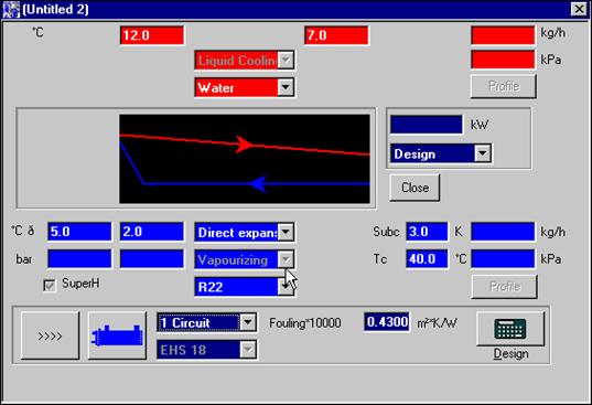
select this application and open a new item, the following window comes up:
NOTE: the evaporating temperature (2 C in the above picture) has to be intended as a dew point temperature for refrigerants with glide. The condensing temperature Tc has always to be intended as the bubble point temperature.
3.1.1 Design calculations
 When you do a
design calculation, you let the program select the most efficient unit for the
input operating conditions. The program ranks all the units with the selected
number of circuits: you can choose units from 1 to 4 circuits.
When you do a
design calculation, you let the program select the most efficient unit for the
input operating conditions. The program ranks all the units with the selected
number of circuits: you can choose units from 1 to 4 circuits.
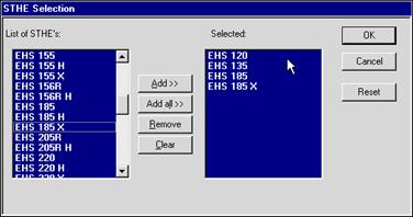
![]() If you want to
limit the models to be ranked, you can click on this button: a new window will
be opened, named STHE Selection. You can clear the list on the right and
create a new list with only the models you are interested in (use the Add>>
button). For example, only four models will be ranked in the case here shown.
If you want to
limit the models to be ranked, you can click on this button: a new window will
be opened, named STHE Selection. You can clear the list on the right and
create a new list with only the models you are interested in (use the Add>>
button). For example, only four models will be ranked in the case here shown.
Here is a list of other inputs given in the above example:
type of brine e.g. Water
inlet brine temperature 12 C
outlet brine temperature 7 C
capacity 135 KW
evaporating temperature 2 C
superheating 5 C
subcooling 3 C
condensing temperature 40 C
type of refrigerant R22
fouling factor 0.43 (it means 0.000043 mK/W)
The brine and refrigerant flowrates are in this case calculated by energy balance equations (you can also give them and let the program calculate the capacity, etc.). The calculated maximum allowed pressure drops (100kPa on hot side, 105.6 kPa on cold side) are not affecting the selection for S&T applications. A simple rule can let you know if a value has been calculated or given as input: calculated values are written in italics.
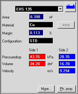
To run the calculation, click the Design button on the bottom right corner. In the results window you will have selected the model with the margin closest to 0 %.
The configuration will be STD or BT (low temperature duty) depending on the operating conditions.
You will have the pressure drop and the volume on both sides, while the velocity will be referring to the cold side.
The buttons More and Ph. prop. are not activated.
![]() To have a look
at a synoptic table with results for all the ranked models, click on the button
To have a look
at a synoptic table with results for all the ranked models, click on the button
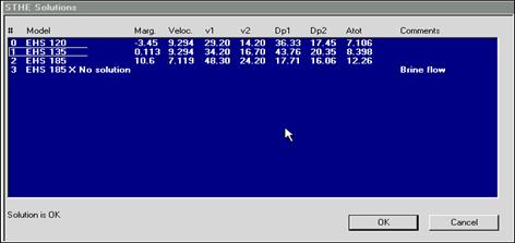
The
window STHE Solutions will be opened.
3.1.2 Rating calculations
You do a rating calculation when you want to evaluate the performance of a particular unit at given operating conditions.
First of all, select Rating as type of calculation. This way, youll be able to select a unit from the list of units. The list of units is related with the number of circuits you selected:
1 circuit ==> EHS units
2 circuits ==> EHD units
3 circuits ==> EHT units
4 circuits ==> EHQ units
Note that the units are listed in alphabetical order.
To run the calculation, click the Rating button on the bottom right corner
For more information, see 3.1.1 Design calculations
S&T Condenser
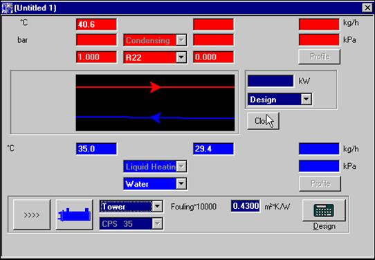
When you select this application and open a new item, the following window comes up:
NOTE: the condensing temperature has to be intended as a dew point temperature for refrigerants with glide.
3.2.1 Design calculations
![]() When you do a
design calculation, you let the program select the most efficient unit for the
input operating conditions. The program ranks all the units associated with the
kind of connection youve chosen: Tower or City.
When you do a
design calculation, you let the program select the most efficient unit for the
input operating conditions. The program ranks all the units associated with the
kind of connection youve chosen: Tower or City.
Note that the default values for the cold side correspond to Tower connection.
If you want to limit the models to be ranked, you can click on the button
Most of the functionality features of the program are the same as described in 3.1.1 for evaporators. Here below youll find only the specific information related with condensers.
The list of other inputs given in the above example is as follows:
type of brine e.g. Water
inlet brine temperature 29.4 C
outlet brine temperature 35 C
capacity 60 KW
condensing temperature 40.6 C
type of refrigerant R22
fouling factor 0.43 (it means 0.000043 mK/W)
You cant give the temperature of the superheated vapour coming out from the compressor; nor you can give the subcooling, which is fixed in the program and equal to 3 C.
To run the calculation, click the Design button on the bottom right corner. In the results window you will have selected the model with the margin closest to 0 %.
As output, you will have the pressure drop and the velocity on the cold side, the volume on both sides, while the reserve of refrigerant will be referring to the hot side.
The buttons More and Ph. prop. are not activated.
3.2.2 Rating calculations
You do a rating calculation when you want to evaluate the performance of a particular unit at given operating conditions.
First of all, select Rating as type of calculation. This way, youll be able to select a unit from the list of units. The list of units is related with the type of connection you selected.
Note that the units are listed in alphabetical order.
To run the calculation, click the Rating button on the bottom right corner
For more information, see 3.1.1 Design calculations
Printouts
All printouts can be done using your Windows fonts and you can also add pictures to your printouts (e.g. you can add your logotype and other pictures directly on your printout template).
All printouts use some templates. These templates can be edited in your word processor. You can edit them yourself and add pictures and/or instructions. All templates use a script language called WRIX to give instructions about the layout and to select the proper parameters to be printed.
The default templates are the followings:
Personal output specification: OUTC200S.TLY
Customer technical specification TECC200S.TLY
In this program version, the above templates give the same printouts.
Appendix C S&T Design considerations
C.1 The program underestimates the EVAPORATORS performances with the following refrigerants: R134a, R407C. This means that you can accept negative margins when selecting a S&T evaporator with such refrigerants, as shown here below:
|
Refrigerant |
Acceptable Margin (%) |
|
R134a | |
|
R407C |
About R404A, it is suggested to use a subcooler in order to have low vapor quality at the inlet of the evaporator. As a general rule, it is recommended to have inlet quality values < 0.4. The maximum subcooled liquid temperature (Max Tsubc) to fulfill this requirement is shown in the following table, as a function of the evaporating temperature:
|
Refrigerant |
Tev (C) |
Max Tsubc (C) |
|
R404A | ||
C.2 CONDENSERS with R407C have to be selected according to the following rule:
up to unit CPL640, keep + 20% margin
units from CPL730 to CPL860 and all CPX: contact AL Sales Dept.
C.3 In the Evaporator application, the evaporating temperature has to be intended as the dew point temperature of the refrigerant at the evaporating pressure; the condensing temperature (Tc) has to be intended as the bubble point temperature.
In the Condenser application, the condensing temperature has to be intended as the dew point temperature of the refrigerant at the condensing pressure.
C.4 The list of brines and refrigerants you can choose from in both S&T applications is the following:
Brines |
Refrigerants |
|
CaCl2 |
R12 |
|
Dowtherm J |
R125 |
|
Eth. Glycol |
R134a |
|
Prop. Glycol |
R22 |
|
Pecasol 60% |
R32 |
|
Pecasol 70% |
R404A |
|
Pecasol 90% |
R407C |
|
Syltherm 800 |
R502 |
|
Tyfoxit 1.1 |
R507 |
|
Tyfoxit 1.15 | |
|
Tyfoxit 1.2 | |
|
Water |
Appendix D S&T examples of printouts
S&T Evaporator application
CAS 200-3.7
Model : EHS 135 STD
Shell side Tube side
Fluids Water R22
No. of circuits --- 1 Circuit
Inlet temperature C 12.0 ---
Outlet temperature C 7.0 ---
Flow rate kg/h 23120 ---
Fouling Factor * 10000 m*K/W 0.43 ---
Evaporating Temperature (Dew) C --- 2.0
Evaporating Pressure bar --- 5.28
Condensing Temperature C --- 40.0
Superheating C --- 5.0
Subcooling C --- 3.0
Pressure drop kPa 43.8 20.3
Volumes dm 34.20 16.70
Velocity m/s --- 9.29
Capacity kW 135.0
Margin % 0
PHYSICAL PROPERTIES
Hot side Cold side
Liquid Vapour Liquid Vapour (Inlet/Outlet)
Dens 999.5/1001 1286/1267 21.90/21.40
Sp.Heat 4.201/4.208 1.216/1.239 0.7465/0.7392
Visc 1.24/1.43 0.232/0.224 0.0123/0.0125
Th.Cond 0.590/0.582 0.0991/0.0966 0.0094/0.0098
Bub. p. 2.0
Dew p. 2.0
Mol.W. 86.48/86.48
Cr.pr. 49.90/49.90
Cr.temp. 96.2/96.2
Lat.heat 203.6/199.4
Units: Density kg/m Viscosity cP
Sp. Heat kJ/(kg*K) Th.Cond W/(m*K)
Temperature C Pressure bar
S&T Condenser application
CAS 200-3.7
Model : CPS 60 STD
Item : Date : 19/07/01
Shell side Tube side
Fluids R22 Water
Connection --- Tower
Inlet temperature C --- 29.4
Outlet temperature C --- 35.0
Flow rate kg/h --- 9226
Fouling Factor * 10000 m*K/W --- 0.43
Condensing Temperature (Dew) C 40.6 ---
Condensing Pressure bar 15.59 ---
Pressure drop kPa --- 51.1
Volumes dm 9.600 3.400
Velocity m/s --- 2.69
Number of passes 4
PHYSICAL PROPERTIES
Hot side Cold side
Liquid Vapour Liquid Vapour (Inlet/Outlet)
Dens 1118/1118 64.63/64.63 994.6/992.7
Sp.Heat 1.437/1.437 1.001/1.001 4.183/4.179
Visc 0.183/0.183 0.0139/0.0139 0.811/0.721
Th.Cond 0.0800/0.0800 0.0121/0.0121 0.616/0.624
Bub. p. 40.6
Dew p. 40.6
Mol.W. 86.48/86.48
Cr.pr. 49.90/49.90
Cr.temp. 96.2/96.2
Lat.heat 166.6/166.6
Units: Density kg/m Viscosity cP
Sp. Heat kJ/(kg*K) Th.Cond W/(m*K)
Temperature C Pressure bar
(END)
|
Politica de confidentialitate | Termeni si conditii de utilizare |

Vizualizari: 3692
Importanta: ![]()
Termeni si conditii de utilizare | Contact
© SCRIGROUP 2024 . All rights reserved