| CATEGORII DOCUMENTE |
| Bulgara | Ceha slovaca | Croata | Engleza | Estona | Finlandeza | Franceza |
| Germana | Italiana | Letona | Lituaniana | Maghiara | Olandeza | Poloneza |
| Sarba | Slovena | Spaniola | Suedeza | Turca | Ucraineana |

DIGITAL+ANALOG SATELLITE RECEIVER
SERVICE MANUAL
DO NOT CHANGE ANY MODULE UNLESS THE SET IS PLUGGED OFF.
ARTEMIS operates with 170-250VAC main supply and this voltage level has THE RISK OF ELECTRICAL SHOCK.
Safety precautions
Servicing of this satellite receiver should only be carried out by a qualified person.
DISCONNECT THE RECEIVER FROM MAIN SUPPLY BEFORE OPENING THE COVER.
SCART CONNECTION
20 18 16 14 12 10 8 6 4 2

19 17 15 13 11 9 7 5 3 1
SCART (TV, VCR, DECODER)
Pin Signal
Audio output B
Audio input B
Audio output A
Audio common return
BLUE return
Audio input A
BLUE
Function switching(Slow switching)
GREEN return
GREEN
RED return
Blanking return
RED
Blanking(Rapid switching)
Video output return
Video input return
Video output
Video input
Common return
Video output : Composite video signal; 1 Vp-p3dB/75 W
Video input : Composite video signal; 1 Vp-p3dB/75 W(for VCR&DEC.)
Audio output : 0.5 Vrms / Z = 1kW
Audio input : 0.5 Vrms / Z = 1kW (for VCR&DEC.)
Function switching : 12V / 6V for 4:3 / 16:9 / Z = 10kW
SERIAL (RS232)
Pin Signal
1. DCD (Data carrier detect)
RXD (Receive data)
TXD (Transmit data)
DTR (Data terminal ready)
GND (Signal ground)
DSR (Data set ready)
RTS (Ready to set)
CTS (Clear to set)
RI (Ring indicator)
INTRODUCTION:
DVB-S Artemis (analog & digital satellite receiver) is designed with ST chipset. The technical information of the receiver will be explained as three parts in the following pages: Power Board, Main Board and Front Panel Board.
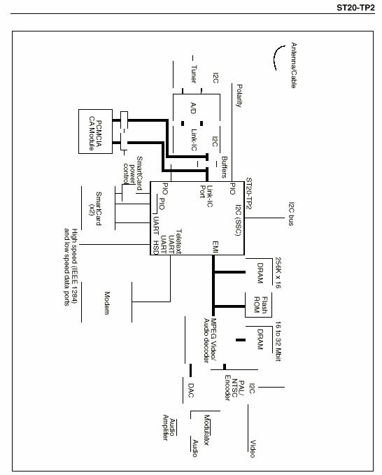
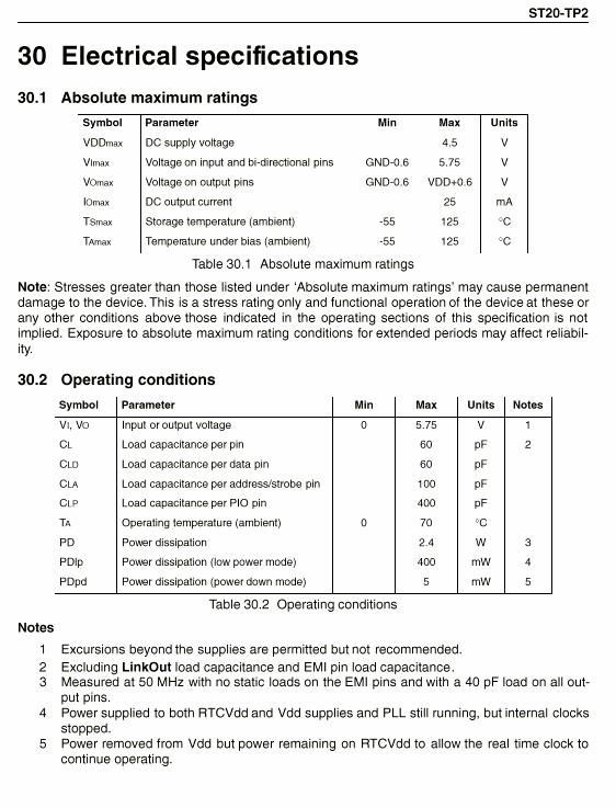
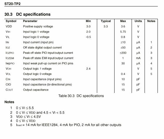
ST20-TP2 (ICS1) Programmable Transport IC for DVB Applications.
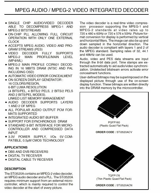
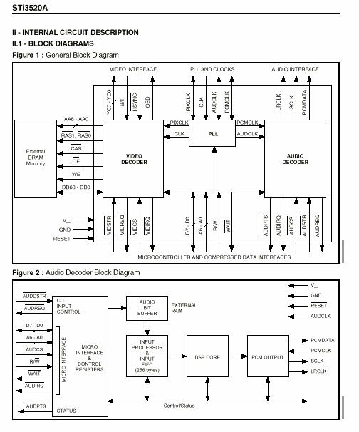
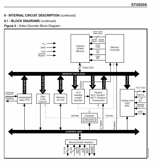
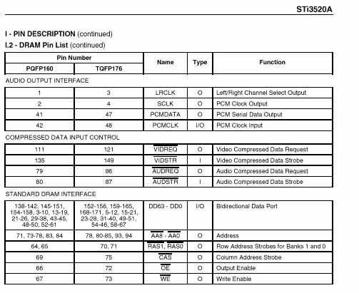
Sti3520A (ICM1) MPEG Audio/MPEG-2 Video Integrated Decoder
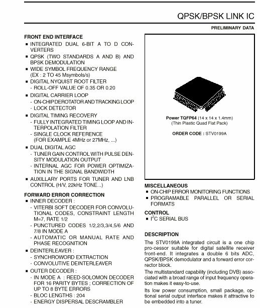
STV0199A (ICL1) QPSK/BPSK Link IC
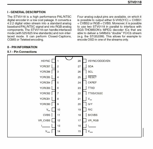
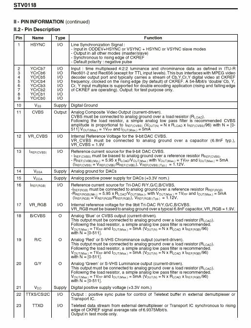
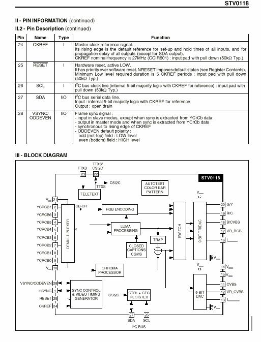
STV0118 (ICV2) PAL/NTSC Digital Encoder
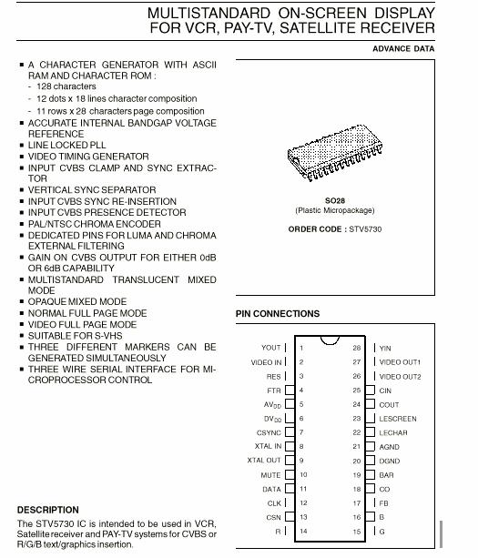
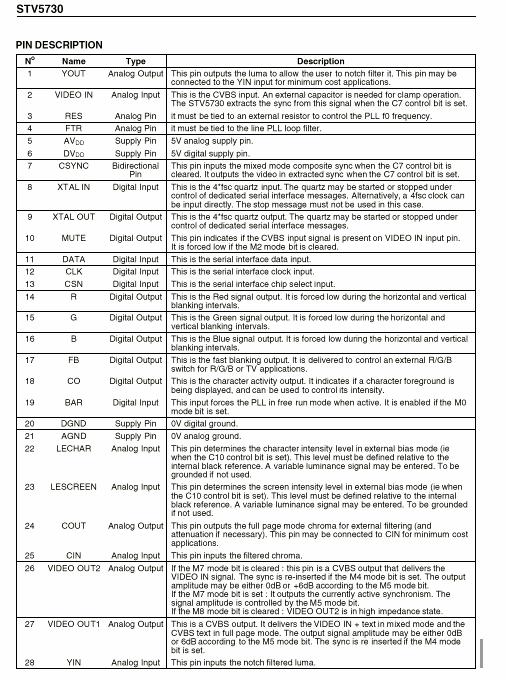
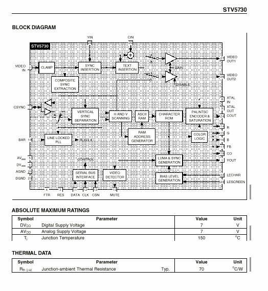
STV5730 (ICN3) Multi-standard OSD (On-Screen-Display) IC
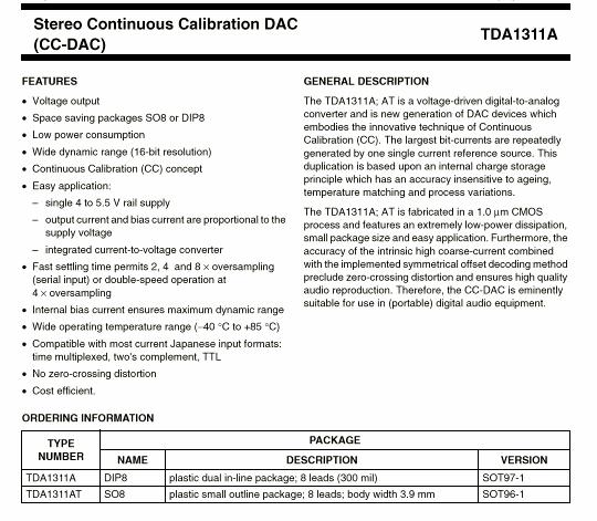
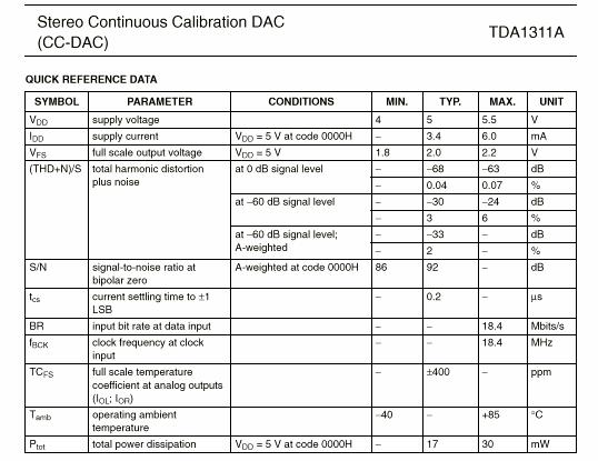
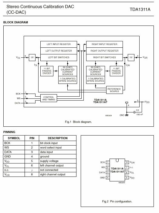
TDA1311A (ICA2) Stereo Continuous Calibration DAC
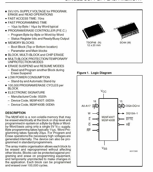
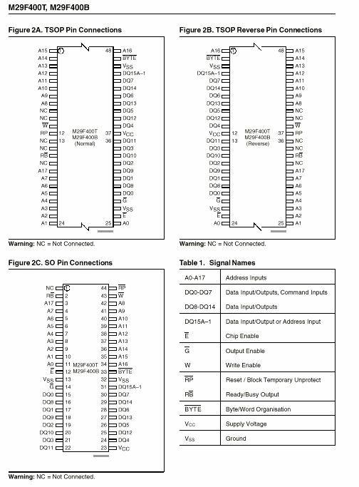
M29F400T (ICSM1, ICSM2) Single Supply Flash Memory
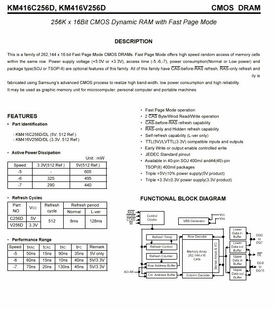
KM416C256D (ICSM3, ICSM4, ICD1, ICD2, ICD3, ICD4) 256 x 16 bit CMOS Dynamic RAM
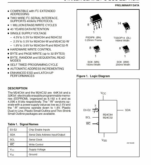
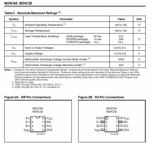
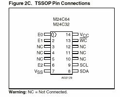
24C65 (ICSM5) 64Kbit Serial EEPROM
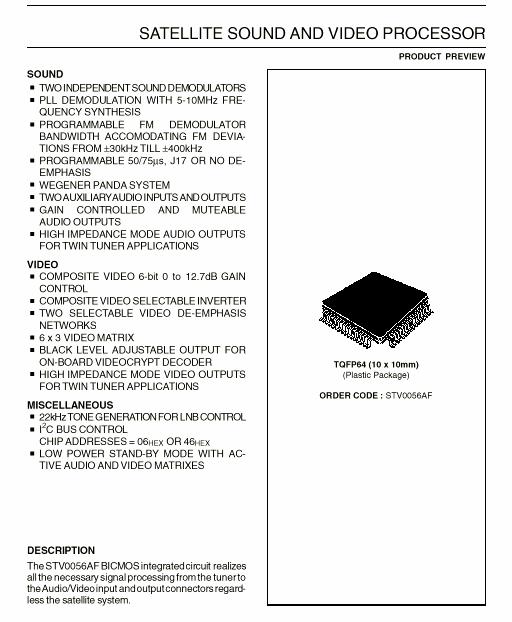
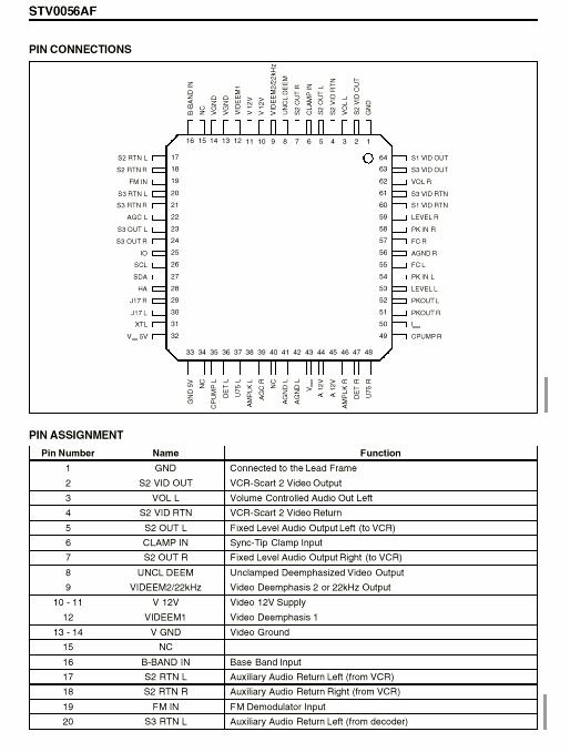
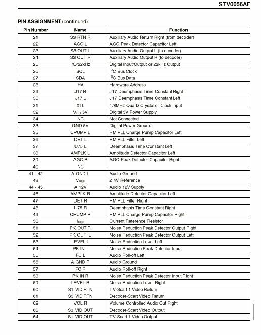
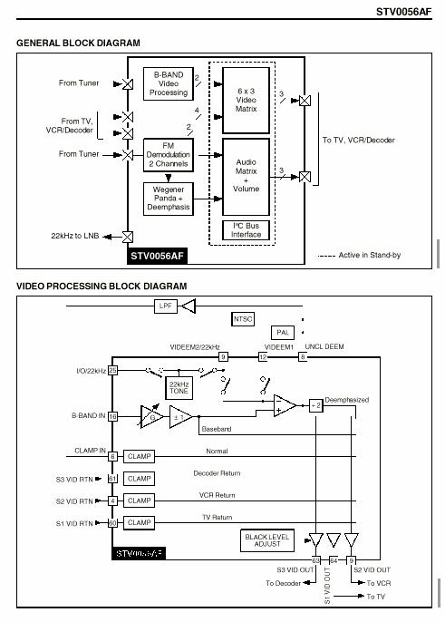
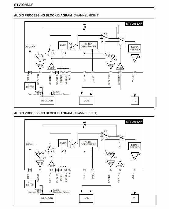
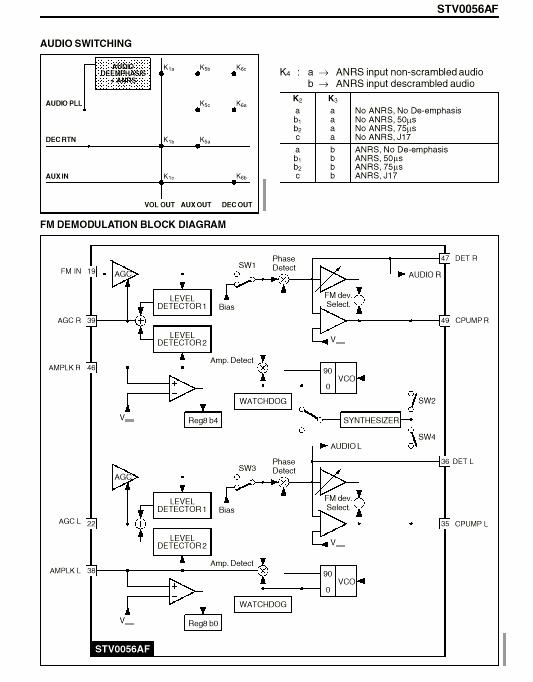
STV0056AF (ICN1) Satellite Sound and Video Processor
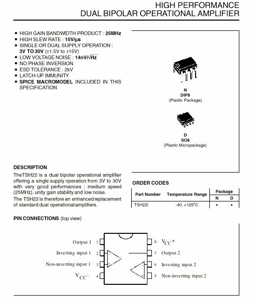
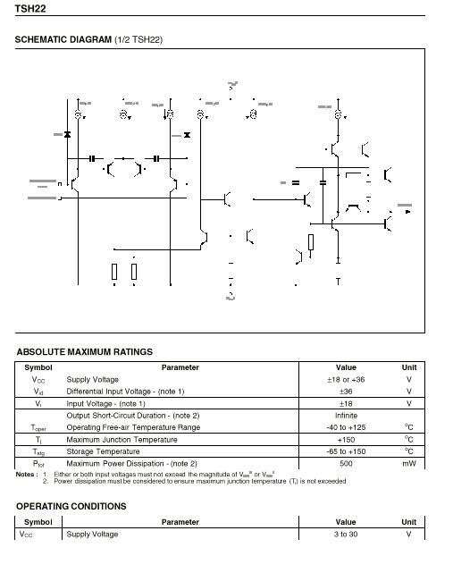
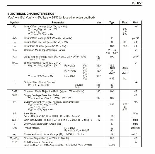
TSH22 (ICS2) Dual Bipolar Operational Amplifier
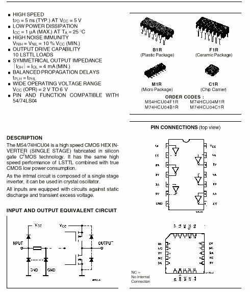
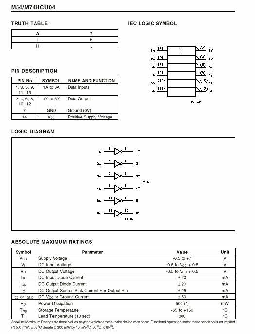
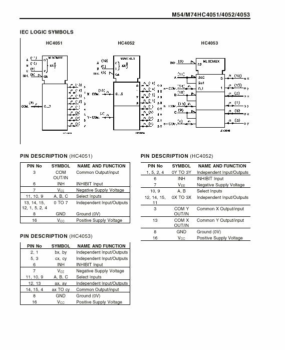
M74HCU04 (ICS3) Hex Inverter
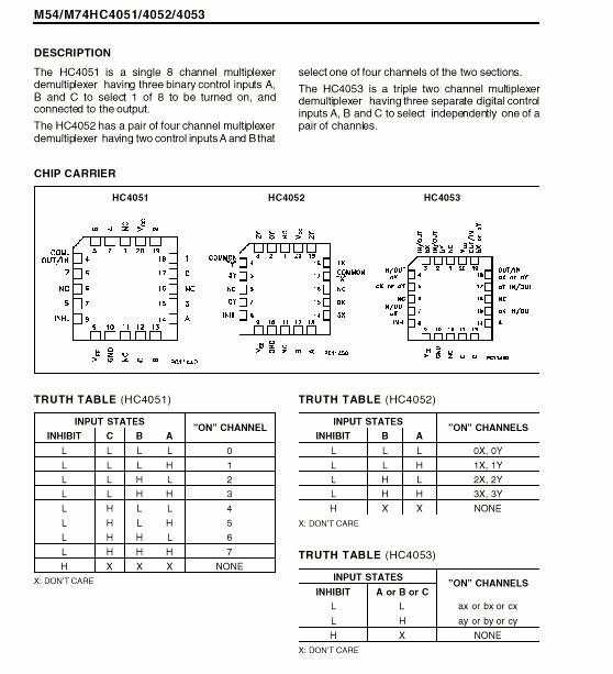
M74HC4052 (ICN2) Analog Multiplexer/Demultiplexer
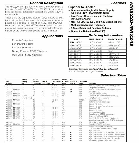
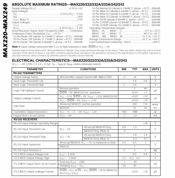
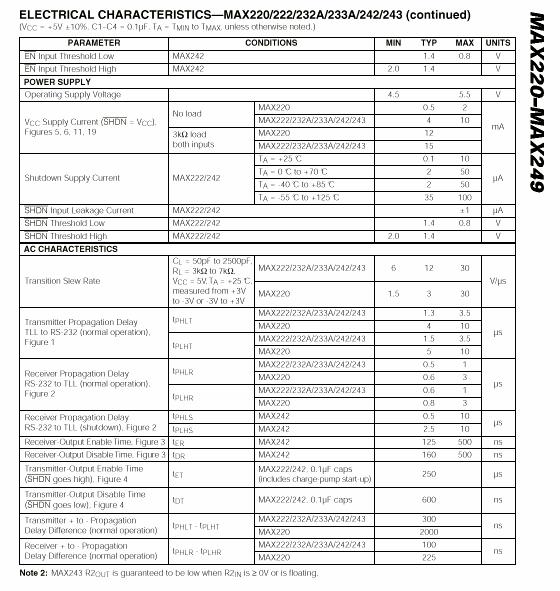
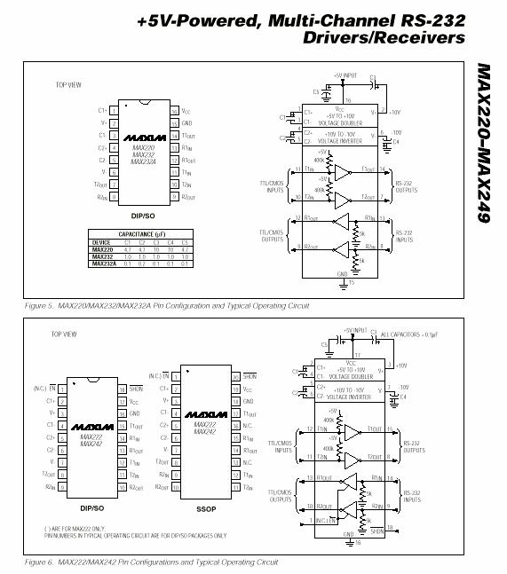
MAX232 (ICS4) RS232 Driver/Receiver
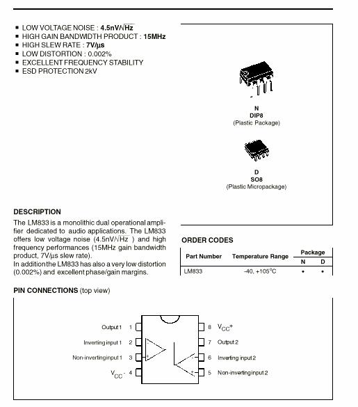
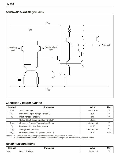
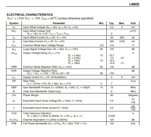
LM833 (ICA1) Low Noise Dual Operational Amplifier
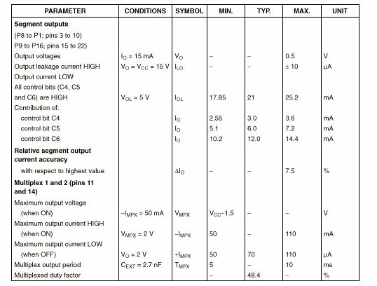
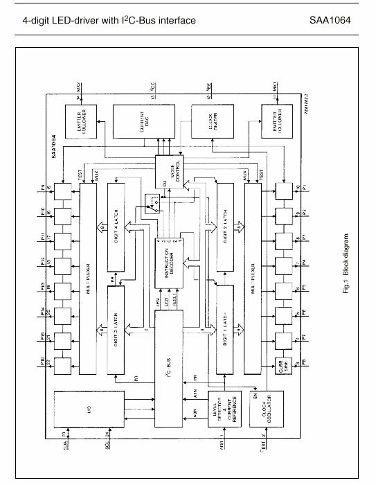
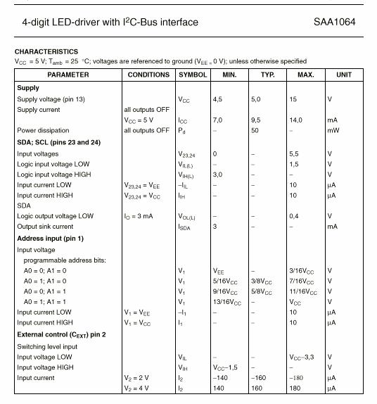
SAA1064 (IC1000) 4-Digit LED driver
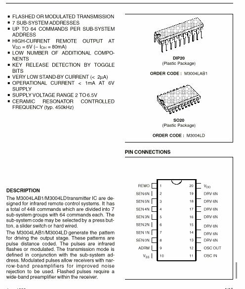
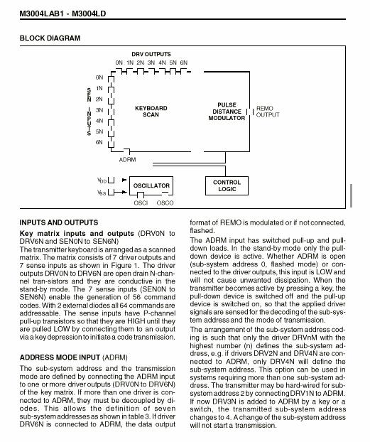
M3004 (IC101) Remote Control Transmitter
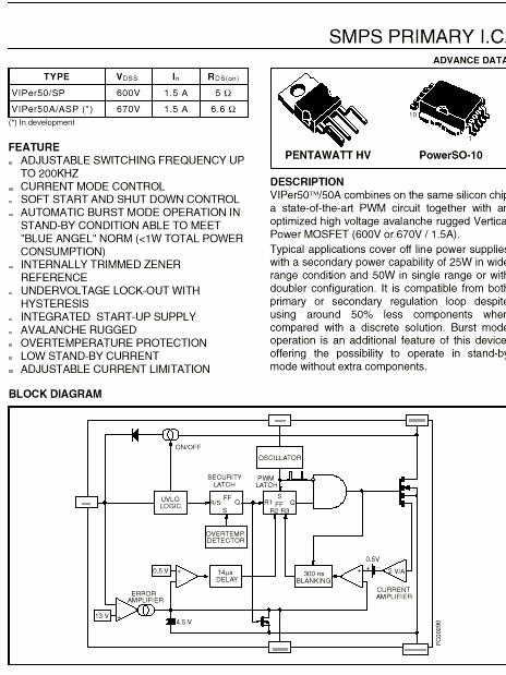
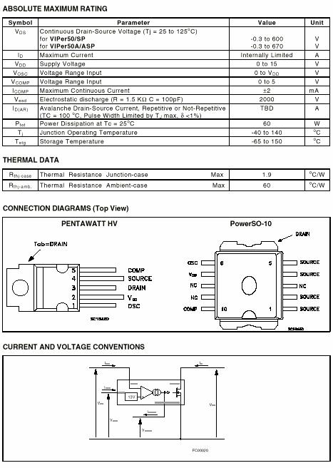
Viper50 (IC100) SMPS primary IC
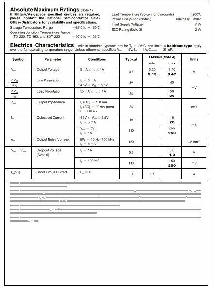
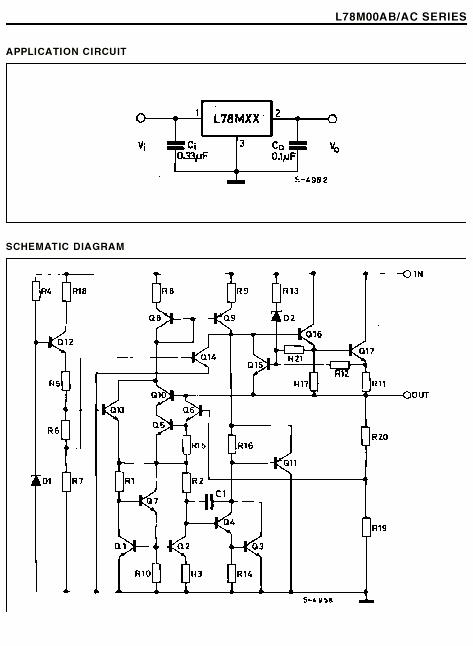
LM3940 (IC103) Low Dropout Voltage Regulator
LM317 (ICL5) Voltage Regulator (for LNB supply)
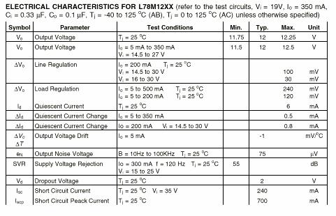
LM7812 (IC102) Voltage Regulator
There is a service menu for service person which is accessed by pressing 1, 9, 1, 9 keys on the remote control respectively while Main Menu is on. This menu consists of five active lines and one line which states software version and build date.
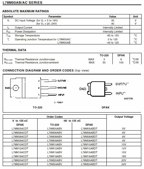
RF Mod. Type : You can control RF modulator option at this line. RF
modulator option can be selected as none or


M29F400T / M29F400B
4 Mb (x8/x16, Block Erase)

M54HCU04
M74HCU04
SINGLE 8 CHANNEL, DUAL 4 CHANNEL, TRIPLE 2 CHANNEL

![]()
M3004LAB1
VIPer50/SP
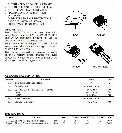
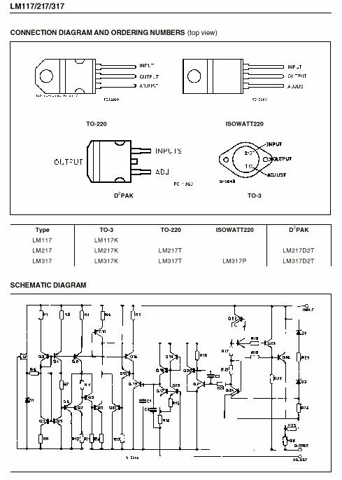
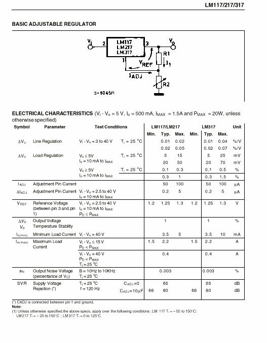
LM117/217
LM317
 |
![]()
DO NOT CHANGE ANY MODULE UNLESS THE SET IS PLUGGED OFF.
ARTEMIS operates with 170-250VAC main supply and this voltage level has THE RISK OF ELECTRICAL SHOCK.
Safety precautions
Servicing of this satellite receiver should only be carried out by a qualified person.
DISCONNECT THE RECEIVER FROM MAIN SUPPLY BEFORE OPENING THE COVER.
RECEIVER DOES NOT WORK (OR CAN NOT SEE ANYTHING ON FRONT PANEL):
heck mains voltage and fuse (F1). If they are OK, check supply voltages (3.3V, 5V, 12V etc.) on power board. Check short circuit on power board. Check reset circuit (QL80, QL81) and clock circuitries on main board (especially 27MHz clock). Check short circuit on main board also especially on data and address busses.
RECEIVER CAN NOT TUNE ANY DIGITAL OR ANALOG TRANSPONDER:
Check LNB supplies for LNB input (DL4 for LNB1, DL71 for LNB2) and tuning voltage of tuner (30V) on D63. If there is no supply, check LM317 (ICL5) circuit and check the switching circuit (Q100, Q101, Q102) on power board for LNB supply.
If the receiver can only tune analog transponders (or only tune digital transponders), check 5V switching circuit (QY2, QY3, QRY1 and QRY2) of tuner. Please check Base Band Video output of tuner on emitter of QL1 for analog channels. If you could not see Base Band video signal, there can be malfunction on IIC bus or tuner is not functioning else check this signal on input pin (pin16) of STV0056 (ICN1). Please check video output (pin64) of STV0056 (ICN1) and pin27 of STV5730 (ICN3). Be sure that video buffers (QN100, QN1) are OK. If you could not see video signal on pin64 of STV0056 (ICN1), please check the suppliers (12VV on CN11, 12VA on CN10, 5VD on CN6) of STV0056 (ICN1).
NO DIGITAL VIDEO SIGNAL ON TV SCART WHEN LOCK LED IS ON:
First of all, be sure that the channel is not scrambled and check CVBS signal using VCR/DECODER scart output. If you get CVBS, probably there are no RGB outputs, check the RGB buffers (QV11, QV12, QV13), switching transistors of Fast Blank (QN90, QN91) and then check RGB outputs on STV0118 (ICV2). If you could not get any video signal from scart outputs, please check CVBS and RGB outputs on STV0118 (ICV2). Please, follow comments about STV0056 (ICN1) above mentioned when you see CVBS signal only on STV0118 (ICV2) output.
NO SOUND ON DIGITAL CHANNELS:
Please check audio L, R inputs (CN66, CN65) of STV0056 (ICN1) and then check pin11 (D_LOUT) and pin4 (D_ROUT) of ICN2 (74HC4052) when you could not see any audio on STV0056 (ICN1) inputs. Finally, check audio outputs of TDA1311 (ICA2).
NO SOUND ON ANALOG CHANNELS:
First, you should check again audio outputs (CN17, CN18) of STV0056 (ICN1). If they are not OK, check supplies (12VV on CN11, 12VA on CN10, 5VD on CN6) of STV0056 (ICN1) and then check de-emphasis circuits (CN42, RN44, CN32, RN29 for 75ms and RN40, CN45, CN44, RN39, RN30, CN36, CN35, RN31 for J17) and measure VREF voltage as 2.4V on CN39. Check the filter circuit (CN2, RN3, RN1, LN1, CN5, and CN3) on base band audio input before STV0056 (ICN1).
NO RF SIGNAL ON RF MODULATOR OUTPUT:
Check Modulator using test pattern signal (press Prog+ & OK buttons at the same time on front panel). If it is OK, check the video signal on RN7 else check QN1.
BAD DECODING ON DIGITAL TRANSPONDERS:
Be sure that Symbol Rate and Frequency of transponder are true. The signal quality and antenna position are very important. Also be sure that you can see the digital OSD properly, if not check any short circuit on DRAMs (ICD1, ICD2, ICD3, ICD4) and Sti3520 (ICM1) address and data buses.
BAD OSD IN ANALOG MODE:
Change 17.734MHz crystal (XN100) or check CN107, CN108 and supply voltages of STV5730 (ICN3).
BAD OSD ON DIGITAL MODE:
Check the RGB buffers (QV11, QV12, QV13), switching transistors of Fast Blank (QN90, QN91) and then check RGB outputs on STV0118 (ICV2). Be sure that there is no any soldering problem on STV0118 (ICV2) and on YUV buses of Sti3520 (ICM1).
NO SOUND FROM VCR SCART:
Please check audio inputs of VCR scart on CN60 (VCR_LIN), CN63 (VCR_RIN).
NO SOUND ON AN ANALOG ENCRYPTED CHANNEL:
Be sure that the frequency and audio settings (de-emhpasis and bandwidth selection) are correct. Check audio outputs (CN61 for R, CN64 for L) of STV0056 (ICN1) for DECODER and then check switching of DECODER audio inputs on ICN2 pins. If you see decoded audio inputs on pins (CN65, CN66) of STV0056 (ICN1), please check audio circuits of STV0056 (ICN1).
NO DiSEqC SWITCHING FUNCTIONALITY:
Check 22kHz signal output (RN94) of STV0188 (ICL1) and then check pin3 of LM317 (ICL5). If it is not OK, change LM317 (ICL5) or external components.
RS232 CONNECTION:
To find any hardware problem on board quickly, use RS232 connection of box and your PC with Windows Hyper Terminal program. You can see any Error Messages by this way on your PC (RS232 settings: Bits per sec = 9600, Data bits = 8, Parity = None, Stop bits = 1, Flow Control = None).
|
Politica de confidentialitate | Termeni si conditii de utilizare |

Vizualizari: 1722
Importanta: ![]()
Termeni si conditii de utilizare | Contact
© SCRIGROUP 2024 . All rights reserved