| CATEGORII DOCUMENTE |
| Bulgara | Ceha slovaca | Croata | Engleza | Estona | Finlandeza | Franceza |
| Germana | Italiana | Letona | Lituaniana | Maghiara | Olandeza | Poloneza |
| Sarba | Slovena | Spaniola | Suedeza | Turca | Ucraineana |
XTEST PROGRAMS
Z-EVOLV.PRG
TEST OF DISTANCE RELAYS PERFORMANCE
WITH EVOLVING FAULTS
Rev. 1.0
GENERAL INFORMATIONS
HOW TO MAKE THE TEST
CONNECTIONS OF THE RELAY
Z_EVOLV: The program
Installation
Running the program
DEFINE SETTING
EXECUTE THE TEST
Test results
|
REVISIONS |
DESCRIPTION |
SIGNATURE |
||
|
N. |
PAGE |
DATE | ||
|
All |
Issued |
Stefani |
||
The program Z-EVOLV.PRG has been developed using the module EDITOR of the software XTEST. This manual describes the revision 1.0.
It allows to perform evolving faults on a distance relay. The purpose is to check the reliability of the relay during a fast changing fault.
With this program the user can define a sequence of two different types of faults. For each of them it is possible to define:
The type of the fault:
Single phase
Phase to phase
Phase to phase and ground
Three phase
The phase under test: Rn, Yn, Bn, RY, YB, BR, RYn, YBn, BRn, RYB.
The fault impedance in module and phase
The direction of the fault: Forward or Reverse
The duration of the fault
This allows, for instance to perform the following test:
Phase to Phase fault RY, at 0.45 W, 35, Reverse, for 0.056 seconds, followed by
Phase to Phase and ground fault RYn, at 0.35 W, 45, Reverse, for 0.3 seconds.
Sometimes relays trip instantaneously after such a fault in reverse direction.
The operators must first connect the relay under test. Run the program
The program requires some parameters:
Source impedance: module, phase angle and earth factor
Earth factor for the line forward
CT side: line or busbar
Type of fault calculation with Source impedance model or Constant current.
Test data
T Connect voltage and current outputs of the test set to the distance relay, as usual.
T Connect the general trip of the distance relay to digital input C1 of the test set as Normally Open. In case there is no general trip you can put the three single phase trip commands in parallel.
T Supply the relay from the test set (unless it is energised by a local supply).
To install the program, insert the diskette in the A: drive.
From DOS or from Program Manager of Windows type A:INSTALL.
The automatic procedure will install all files into the correct directories, together with other distance relay test programs.
To run the program, start the module RUN of the software XTEST.
Then select File
- Open from the menu, or click on ![]() of tool-bar.
of tool-bar.
Select the directory C:XTESTPRG
Select Z_EVOLV.PRG and then press OK to confirm.
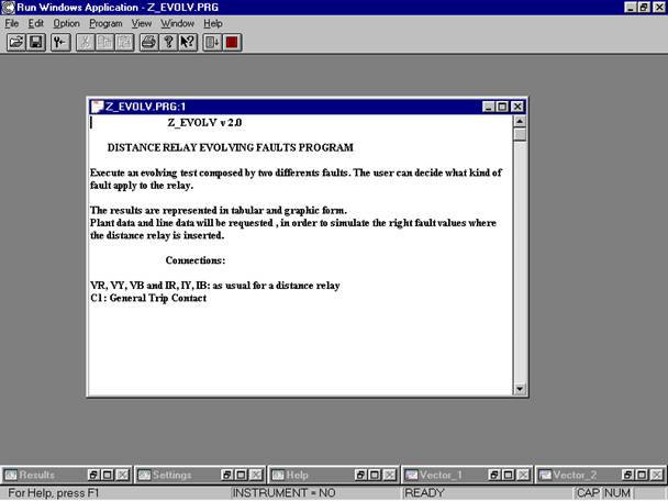
The program starts and the following screen will appear.
|
|
|
|
|
|
At the bottom are indicated the all used by the program during the execution.
Start the program
by pressing the icon ![]()
|
|
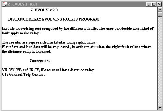
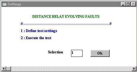
The following window will open-up (better to expand at full screen).
It is a menu where the user must decide whether to define all settings for the test or go straight away to the test itself.
In case the user select to define the setting, a series of input windows will be presented
|
|
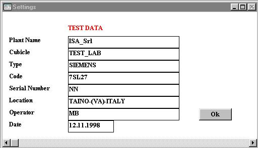
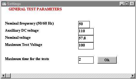
The first window requires that the user defines all test datas:
The meaning of the input fields is obvious. Press OK to continue.
|
|
In the second windows well have to define:
The meaning of these parameters is also well known. Any way test parameters are summarised in the following table.
|
Field |
Default Values |
Notes |
|
Nominal Frequency |
The fault calculation is made at constant current. The fault current must be less than: 57.8/(2*Zmax), with Zmax = maximum fault impedance. |
|
|
Auxiliary DC Voltage |
110 Vdc |
If the relay is powered on by the auxiliary power supply of the plant, this voltage from the UTS is not necessary. |
|
Nominal Voltage |
57,8 Vac |
In case of a PT with secondary of 110 V, this value should be 63 V. |
|
Maximum test voltage |
Sometimes it is necessary to reduce this value when testing old electromechanical relays with source impedance ZS model to avoid overloads on voltage amplifiers (usually it is enough to limit it at 62,5 V); it wont be applied to the model DRTS due to its already low output power. |
|
|
Max time for the Test |
It defines a timeout for each test in order not to wait too long in case the relay does not trip. |
|
|
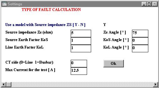
After this, pressing the button OK, the following window is presented:
|
|
The user must decide if the model to be used is with source impedance. If yes, then all source parameters must be defined:
otherwise the test will be performed at constant current and the unnecessary parameters wont be displayed.
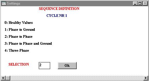
When executing the test, as already said, we have to define fault parameters for cycle 1 and 2.
|
|
The first window requires that the user defines type of fault for the first cicle:
|
|
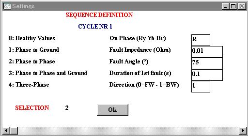
Once the type of fault is selected, the user is asked to define the following parameters:
which are:
Phase under test according to the type of fault
The fault impedance (module and phase)
Duration of the first fault
Direction of the fault : forward or backward
The same the user must do for the second cycle, after which the defined sequence will be executed and the result presented in the input window and stored in the result one.
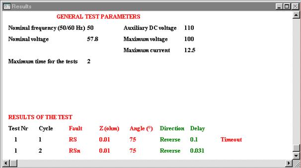
A table form result is opened at the end of the test. The first part of the table is the summary of all selections made for the test.
The second part includes test number, fault type, fault impedance (module and phase), fault direction and trip time.
|
|
This example shows a typical error: an evolving fault in back direction is cleared instantaneously as soon as the fault changes from Phase to Phase to Phase to Phase and Ground.
|
Politica de confidentialitate | Termeni si conditii de utilizare |

Vizualizari: 1070
Importanta: ![]()
Termeni si conditii de utilizare | Contact
© SCRIGROUP 2024 . All rights reserved