V
SeriestS
IP
Camera
USER MANUAL

Version V1.0 Release
Index
1 Introduction.. - 1 -
1.1 Welcome to the IP Camera.. - 1 -
1.2 Identify IP Camera.. - 2 -
2 Functions and Features.. - 8 -
2.1 Basic Functions. - 8 -
2.2 Advanced Features. - 9 -
3 System Requirement.. - 9 -
4 Setup Procedure.. - 10 -
4.1 IP Camera Power & Network Connection.. - 10 -
4.2 Router/Switch/Hub/xDSL Modem Connection.. - 11 -
4.3 Use IPCamSearch Tool to setup IP
Cameras. - 12
-
4.4 View Video on Web Browser.. - 14 -
4.5 Setup IP Camera on Web.. - 16 -
4.6 Mounting the IP Camera.. - 16 -
5 System Configuration.. - 17 -
5.1 System status. - 17 -
5.2 User Management.. - 18 -
5.3 Network.. - 19 -
5.4 Date and Time. - 19 -
5.5 Video.. - 20
-
5.6 JPEG Encryption.. - 20 -
5.7 E-mail. - 22
-
5.8 FTP. - 23
-
5.9 Sensors and Motion Detection.. - 23 -
5.10 Scheduler Trigger.. - 24 -
5.11 System Maintenance. - 24 -
5.12 System Log.. - 25 -
5.13 Guest Zone. - 25 -
6 Visit IP Camera over INTERNET.. - 26 -
6.1 WAN IP Address. - 26 -
6.2 Network Address Translation (NAT) - 27 -
6.3 Port Forwarding.. - 27 -
6.4 Default Gateway.. - 28 -
6.5 Accessing Multiple Cameras over the Internet.. - 28 -
6.6 Dynamic Domain Name Service (DDNS) - 29 -
6.7 Configuration Example. - 30 -
7 Technical Parameters.. - 31 -
Figures and Tables Index
Figure 1 IP Camera 45-angle View.. - 2 -
Figure 2 IP Camera Front View.. - 2 -
Figure 3 IP Camera Back View.. - 3 -
Figure 4 Front View Indication and Operation. - 3 -
Figure 5 LCD Indications. - 4 -
Figure 6 IP
Address/Network Mask/Gateway loop show.. - 4 -
Figure 7 Back View Indication. - 6 -
Figure 8 Input & Output defines. - 6 -
Figure 9 Input & Output Pins Connection. - 7 -
Figure 10 Insert a CF Card. - 8 -
Figure 11 Connecting the Ethernet wire. - 10 -
Figure 12 connecting the power supply. - 11 -
Figure 13 LAN connection. - 11 -
Figure 14 IP Camera Search Tool - 12 -
Figure 15 Modify IP Camerats IP Address. - 13 -
Figure 16 Input Administratorts Username and Password. - 13 -
Figure 17 IP Camera Home Page. - 14 -
Figure 18 Login Message box. - 14 -
Figure 19 Video webpage. - 15 -
Figure 20 History Images View.. - 16 -
Figure 21 System Status View.. - 17 -
Figure 22 User Management View.. - 18 -
Figure 23 Network Setup View.. - 19 -
Figure 24 Date and Time Setup View.. - 19 -
Figure 25 Video Setup View. - 20 -
Figure 26 JPEG Encryption Setup View.. - 20 -
Figure 27 Require Password Input in Client Web Browser - 21 -
Figure 28 Input Password in Web Browser (ActiveX) - 21 -
Figure 29
Input Password in Web Browser (Java) - 21 -
Figure 30 E-mail Setup View.. - 22 -
Figure 31 FTP Setup View.. - 23 -
Figure 32 Sensors and Motion Detection Setup View.. - 23 -
Figure 33 Scheduler Trigger Setup View.. - 24 -
Figure 34 System Maintenance View.. - 24 -
Figure 35 System Log View.. - 25 -
Figure 36 tGuest Zonet View.. - 25 -
Figure 37 IP Camerats Application Environment - 26 -
Figure 38 Typical Network Environment - 30 -
1
Introduction
1.1 Welcome to the IP Camera
The IP Camera combines a high quality digital video
camera with network connectivity and a powerful web server to bring clear video
to your desktop from anywhere on your local network or over the Internet.
|

|
Your IP Camera package should contain the
following items, If any of the listed
items are missing, please contact your reseller from where you purchased the
camera for assistance.
|
The package includes.
IP Camera *1
IP Camera Utility CD *1
5V Power Adapter *1
Stand of plastic*1
1.5 meter cable*1
1.2 Identify IP Camera
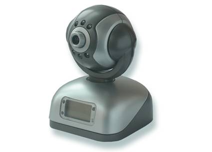
Figure 1 IP Camera
45-angle View

Figure 2 IP Camera
Front View

Figure 3 IP Camera
Back View

Figure 4 Front View
Indication and Operation
The privacy button toggles Privacy mode and Normal mode, In Privacy mode,
all the remote users will not be allowed to see the video.
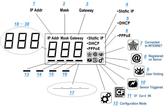
Figure 5 LCD
Indications
LCD will loop show IP Address/Network Mask/Gateway,
as shown in the Figure 6.

Figure 6 IP Address/Network
Mask/Gateway loop show
Status icon indications list:
|
Icon
|
Meaning
|
|

|
DDNS Server Registered. Connected to
the INTERNET successfully.
|
|

|
Backbone server connected
successfully.
|
|

|
There is/are user(s) visiting IP
Camera video.
|
|

|
Sensor triggered. (Digit input or
Motion detection)
|
|

|
CF card detected.
|
|

|
System in configuration status. E.g.
Upgrading firmware.
|
Network mode indicationss
|
Icon
|
Meaning
|
|
Static
IP
|
Use
static (manually fixed) IP mode.
|
|
DHCP
|
IP Address
is dynamically assigned by DHCP Server.
|
|
PPPoE
|
IP
Camerats internal PPPoE dial function enabled.(Used for xDSL)
|
Working status LED meaning:
|
LED Status
|
Meaning
|
|
Normal Flashing:
Turns on for 1/2 second every 3 seconds
|
Normal running
|
|
Always on or always off
|
System error
|
|
Fast Flashing:
Turns on for 1/2 second every 1 second
|
System is starting, Please wait.
|
|
Slow Flashing:
Turns on for 1/2 second every 6 second
|
Upgrading firmware, Please wait.
|

Figure 7 Back View
Indication

Figure 8 Input &
Output defines
Input Pins: The input pins can be used
for 2-way external sensor input. For example, you may connect a Person Infrared
Sensor (PIR) to it for motion detection. When external sensor triggered, IP
Camera can be programmed to send an email with picture or control the internal
relay output.
Input pins can connect 2 sensors. The sensor should
provide open/close signal only. The two lines of sensor 1 should connect to Pin
3 & Pin 4; the two lines of sensor 2 should connect to Pin 5 & Pin 4.
Output Pins: IP Camera has an internal
relay. Relayts two normally open contacts are represented by Pin 1 and Pin 2.
You may use it to control one external load below AC/DC 36V & 2 Amp.
While
connecting input and output pins, strip off the protect rubber of wire for 5mm, the use a small screwdriver to depress and latch down the orange tabs over
holes, Insert the red wire into hole until the insulation just reaches the back
of the camera, use the screwdriver to press down and release the orange tab
above hole locking the wire in place. Repeat the steps for other wires.
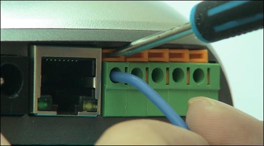
Figure 9 Input &
Output Pins Connection
External Power SocketsConnect to a 5V AC-DC adapter.
|

|
CAUTION: Make
sure to only use the power adapter supplied with your IP Camera. Using a
non-approved power adapter may damage the camera.
|
RJ-45 Ethernet Socket: Connects your IP Camera to
LAN.
CF Card Socket: Insert a Compact Flash Card
for scheduler or sensor triggerts images storage. Support volume is 1MByte to 2GByte. CF Card should be format as
FAT16/FAT32 before inserted.
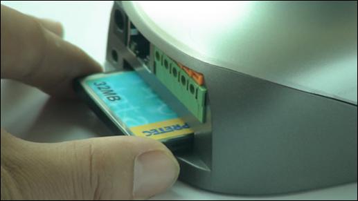
Figure 10 Insert a
CF Card
|
|
Caution:
IP Camera DO NOT
allow plug/unplug CF Card when power up. You must unplug IP Camerats
power before operating CF Card.
|
|

|
Note: Please
keep in mind, not all brand and modets CF card can work with IP Camera,
please take a test before purchase.
|
RESET button: Click
the reset button shortly, will reboot the system. If you press the button and
hold for 5 seconds or longer, the system will restore to factory default
configuration, it will take about 30 seconds, then reboot automatically.
|
|
Caution:
DO NOT switch off IP Camerats power during the procedure of
restoring factory default. It will take about 30 seconds.
|
2
Functions and Features
2.1
Basic Functions
The IP
Camera and your home or business network
form a powerful audio/video remote monitoring solution. Just place the IP
Camera anywhere on your network, power it up, and itts ready to be accessed by
any PC on the network running web browser. The IP camera utilizes MJPEG
hardware compression, brings 30fps@VGA resolution live video to you.
The built-in pan and tilt,
live streaming audio, and snapshot/video capture functions can all be
controlled directly from the camerats on-board homepage. Capability for motion
detection with e-mail notification may be added by purchasing an optional
motion detector.
Use the IP Camera to keep an
eye on your home or business when you cantt be there. Give friends and
relatives a window into your world or monitor and record anything from anywhere
on the Internet.
2.2
Advanced Features
Advanced Image Encryption
Besides basic web authority mechanism, IP Camera provide an 128-bit AES
encryption to the images transportation, ensures your information security.
Digital Video Recording and
Transportation
IP Camera can store images to CF Card, or, send images to your mailbox
when triggered.
Motion Detection
Your may use the internal Motion Detection function or external PIR sensor
to trigger images recording and transportation.
Relay Output Control
The internal relay can be used to control external devices according to
your setting.
DDNS support
IP Camera provides dynamic DNS function, thus
you may use it in xDSL environment.
3
System Requirement
LAN: 10Base-T
Ethernet / 100BaseTX Fast Ethernet
Web Browser can
support ActiveX ,such as Internet Explorer 5.0 or higher,
Web Browser can
support Java Applet, such as Firefox 1.5
PC C Intel
Pentium III or equivalent, 1GHz or above
128MB RAM
800x600
resolution with 16-bit color or above
Windows 2000,
Windows XP, Linux
Other device:
read-only CD-ROM
|
|
Note:
Not only the fixed IP address can access cameras from the Internet, but also
Dynamic IP can access cameras. If the IP address provided by your Internet
Service Provider is dynamic (changing), then signing up for a dynamic DNS
service will make accessing from the Internet much more convenient.
|
4
Setup Procedure
Before use IP Camera, please setup according to the
following procedures.
4.1 IP
Camera Power & Network Connection
Plug the included Ethernet cable into the RJ-45 connector at the back of
the camera as shown.
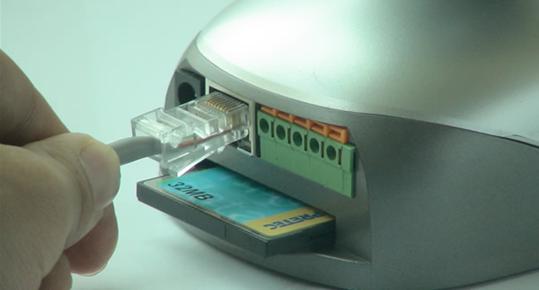
Figure 11 Connecting
the Ethernet wire
Connect the power supply to the back of the camera as
shown, and then plug the supply into an available power outlet.
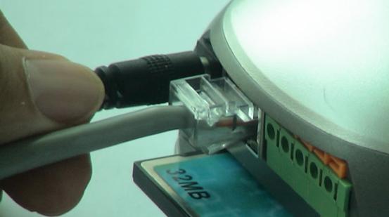
Figure 12 connecting
the power supply
|
|
CAUTION: Make sure to only use the power adapter supplied with
your IP Camera. Using a non-approved power adapter may damage the camera.
In different country or region, the power supply might be different
(110V/220, 50Hz/60Hz), please make sure it correspond to the tag marked on
the power adapter.
|
4.2
Router/Switch/Hub/xDSL Modem Connection
Plug the other end of the Ethernet cable into any
available LAN port. A typical home
router/gateway connection is shown below. The LED of LAN port will then turns
ON.
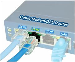
Figure 13 LAN
connection
Check the LEDs on the RJ45 socket of IP Camera. If
connection is ok, the green LED turns on. If therets any active data
transportation, the orange LED will flash.
The LCD panel of IP Camera will show IP Camerats current IP
address/Network Mask/Gateway.
IP
Camera is available for visiting now. You have two methods to visit its
homepage:
1
Run IPCamSearch Tool in the CD. This software will search
for all IP Cameras in your LAN. Select one and then click [visit] to continue.
2
Run an Internet Explorer, and input the IP address as shown
on the LCD to IEts address bar, for example: https://192.168.0.234.
|

|
Note: IP Camera
by default use fixed (static) IP address setting. The default IP address is :192.168.0.234,
Network Mask is 255.255.255.0, Gateway is 192.168.0.1
|
4.3
Use
IPCamSearch Tool to setup IP Cameras
Put the supplied CD into
your CDROM, Click and run IPCamSearch.exe Tool.

Figure 14 IP Camera
Search Tool
This
tool shows all IP Cameras found on your LAN with its Serial Number/IP
Address/Firmware Version. If your IP Camerats IP address is not as the same
segment of your PC(defined by IP Address and Network Mask), you may not be able
to visit your IP Camera. For example, Your PCts IP address is 192.168.100.33,
network mask is 255.255.255.0, then your PC will only reach IP address
192.168.100.1 to 192.168.100.255, If your IP Camerats IP Address is not within
this range, you cannot access it. Then you may click [Setup IP] button to
change IP Camerats IP address to adopt your PC setting.
Click
[Auto Set], let IPCamSearch.exe tool find an available IP Address for you.
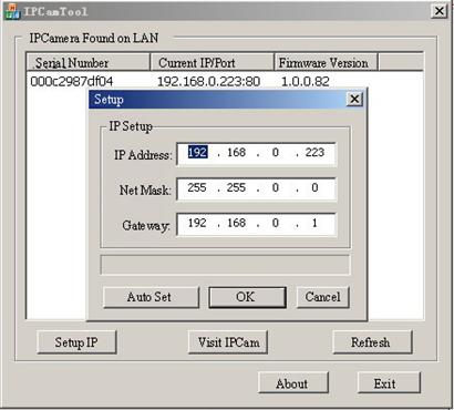
Figure 15 Modify IP
Camerats IP Address
Click [OK], and then input administratorts username
and password to continue.
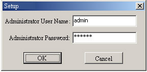
Figure 16 Input
Administratorts Username and Password
|
|
Note: By default, administratorts
username is: admin,
password is: 123456
|
Input
the correct username and password, and click [OK], then you can see a message
box indicating IP Camerats IP Address has changed(IP Camera is in static IP
mode now).
Then
you may click [Visit IPCam] to run an Internet Explorer, You can do more
configuration by click [System Setup] on homepage of IP Camera.
|
|
Note: If you dontt have IPCamSearch.exe tools at hand, you may
change your PCts IP Address to the same segment, according to the IP shown on
IP Camerats front LCD. Then you can input IP Camerats IP Address into IEts
address bar to access.
|
4.4
View Video on Web Browser
You
may visit IP Camerats homepage by IE or other compatible web browsers.
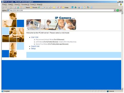
Figure 17 IP Camera
Home Page
Click
tUser Visitt to view video. You will see a message box which requires your
login as shown below.
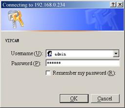
Figure 18 Login
Message box
|
|
Note: By default, administratorts
username is: admin,
password is: 123456
|
Input
correct Username and password, then you can view the video. If you are using IE ActiveX mode, for the first time,
you will be alert to install ActiveX control. Click [Install] to continue. After ActiveX Control
Installed, you will see the following.
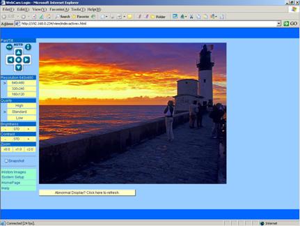
Figure 19 Video
webpage
On
the top-left of the web page is a pan/tilt control, you can click to move the
camera Up/Down/Left/Right, and left-right cruise180 degree or top-down cruise120
degree, or return to home position. Note, Do not cruise long time continually.
On
the left, you can also select the Resolution, Quality, Brightness, Contrast and
Zoom.
Resolution
can be 640x480, 320x240, and 160x120. The higher resolution, the higher
clarity, while requiring more bandwidth.
Quality
can be tHight, tStandardt or tLowt. tHight consumes largest bandwidth, thus the
frame per second will down.
If
you feel the frame per second (fps) is too slow, and hope to increase it, you
may select tLowt quality and lower resolution. If you hope to see clearer
image, you may choose tHight quality and higher resolution.
Brightness
and Contrast can be changed according to different environment. t+t means add,
t-t means reduce. tSTDt means a standard (middle) value.
Zoom
will show the video in a scale of half or double. It wontt affect the transport
fps or bandwidth.
Click
[Snapshot] will pop up a new page to snap a static JPEG image, you may click
right key of mouse and select tsave astt to store it to your computer.
Click
[History], will pop up a History View Page (You must have inserted CF Card
first).
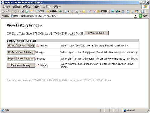
Figure 20 History
Images View
4.5 Setup IP Camera on Web
You can click [System Setup] to
modify all parameters. See the Chapter 5 for details
.
4.6
Mounting the
IP Camera
The IP Camera
can sit on a flat surface, such a shelf or bookcase, be mounted to a wall using
the included bracket, or mounted atop a tripod stand using the standard tripod
mount located on the underside of the base. When using the camera free standing, be
sure to secure the cables. Failing to secure the cables could cause the camera
to be pulled off the mounting surface resulting in damage to the camera.
|
|
CAUTION: The IP Camera should be mounted indoors or
inside a weatherproof enclosure.
Outdoor exposure may result in damage and will void your warranty.
|
|
CAUTION: Dontt mount the IP Camera with the lens
facing into direct sunlight. Prolonged exposure to direct sunlight will
damage the sensor.
|
The mounting bracket included with your camera
provides convenient mounting to vertical surfaces, such as walls. The camera
support platform can be tilted up or down to help point the camera toward your
area of interest. You can also rotate the camera in any direction on the
platform.
Step 1. Find a suitable location to mount the camera.
Step 2. Using the mounting
bracket as a guide, mark the location of the two mounting holes.
Step 3. Drill a ¼t hole for each screw.
Step 4. Use a hammer to tap the two plastic anchors into the
holes.
Step 5. Use the two screws to fasten the bracket to the wall.
Step
6. Place
the camera on the mounting bracket platform and rotate the camera to be facing
in the desired direction.
Step
7. Secure
the camera to the mounting bracket using the thumbscrew located on the bottom
of the platform.
Step
8. Loosen
the tilt adjust thumbscrew and tilt the camera toward the area to be observed.
5
System Configuration
5.1 System
status
This page shows status of
the system for diagnose.
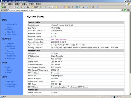
Figure 21 System
Status View
5.2
User Management
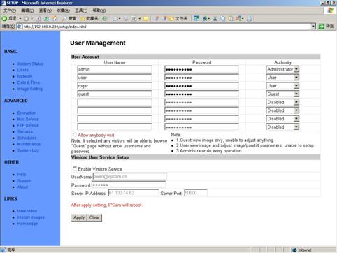
Figure 22 User
Management View
tUser
namet: Determine the username of visitor who can log in. The administrator can
set up to 16 case sensitive character names.
tPasswordt:
Set up a password for the visitor account. The password must be between one and
sixteen bytes which is English and number.
tAuthorityt: Determine the
permission lever to tAdministratort, tUsert, tGuestt or tDisabledt.
|
Administrator:
|
This permission allows the user full access
including write permission to all the sections.
|
|
User:
|
This permission level allows the user access to
IP Camera menus, but without the permission to setup.
|
|
Guest:
|
This permission level allows the user to access
IP Camerats video only. The user does not have any permission to change.
|
|
disabled
|
Make the user account
disable, no access.
|
tAllow Anybody Visitt: IP Camera provide a Guest Zone, if you
checked this, any temporally visitors may enter Guest Zone to see the video
without input any username/password. If you unchecked this (default), the
visitors have to enter at least a tGuestt permission username/password to visit
the tGuest Zonet. At any time, the tUser Zonet only allows tUsert &
tAdministratort permission to visit.
5.3
Network
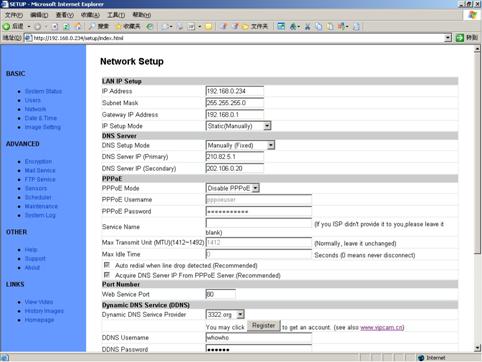
Figure 23 Network
Setup View
5.4
Date and Time
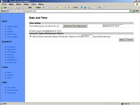
Figure 24 Date and
Time Setup View
5.5
Video
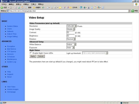
Figure 25 Video Setup View
5.6
JPEG Encryption
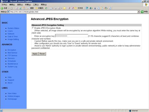
Figure 26 JPEG
Encryption Setup View
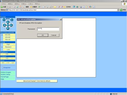
Figure 27 Require
Password Input in Client Web Browser
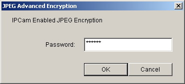
Figure 28 Input
Password in Web Browser (ActiveX)
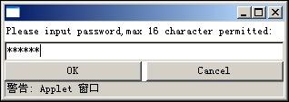
Figure 29 Input Password in Web Browser (Java)
5.7
E-mail
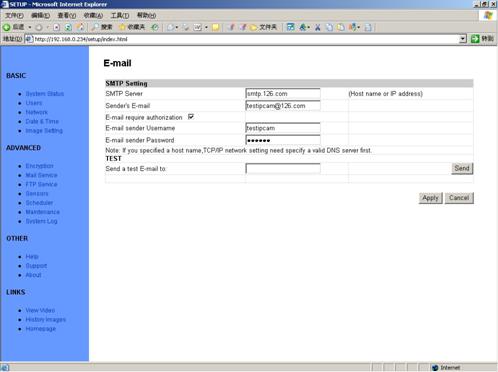
Figure 30 E-mail
Setup View
This section sets up the necessary
Email server information. The administrator will have to enter a valid Account
Name and Password to the Email server. This information is necessary to allow
email notification features.
tSMTP Servert: The administrator will
have to enter the Email server address here.
tSenderts Emailt: This will determines
IP Camerats Email address.
tEmail Requires Authenticationt: If
checked, the administrator will have to provide the account name and password
in order to access the Email server.
tE-mail Sender Usernamet: Enter the
account name or login name to the Email server.
tE-mail Sender Passwordt:
Enter the password for the above account name.
5.8
FTP
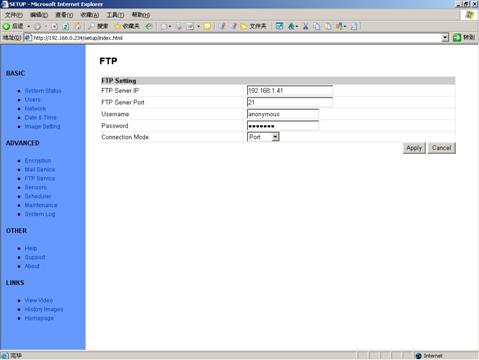
Figure 31 FTP Setup
View
5.9
Sensors and Motion Detection
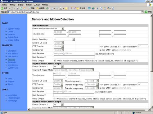
Figure 32 Sensors
and Motion Detection Setup View
5.10 Scheduler
Trigger
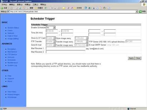
Figure 33 Scheduler
Trigger Setup View
5.11 System
Maintenance
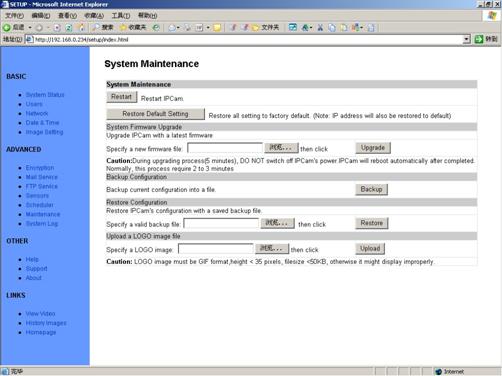
Figure 34 System
Maintenance View
5.12 System
Log
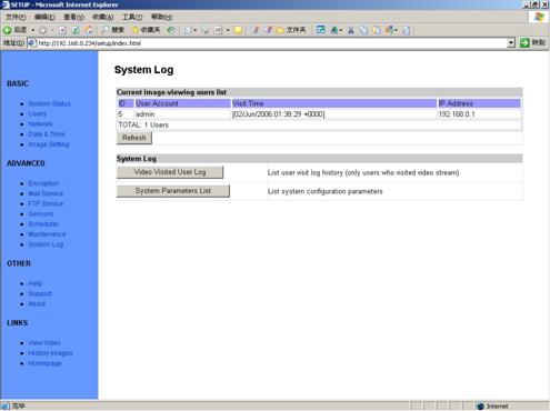
Figure 35 System Log
View
5.13 Guest
Zone
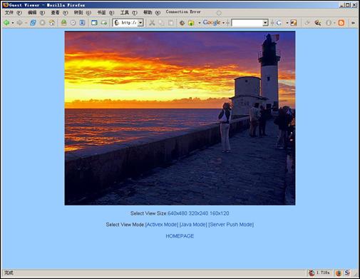
Figure 36 tGuest
Zonet View
6
Visit IP Camera over INTERNET
IP Camera is often used in
this environment:
1 In Local Area Network (LAN) only.
2 Direct connect to INTERNET via xDSL (PPPoE) Modem.
3 Share one INTERNET connection with other computer,
and connect to INTERNET via a gateway or router.

Figure 37 IP
Camerats Application Environment
If your LAN is connected to
the Internet through a high speed (broadband) Internet connection, you can
access your cameras by web browser from anywhere on the Internet. To do this
you need to:
1 Know your WAN (Internet)
IP address. This is the IP address
that your Internet Service Provider gives you to access the Internet. It may be
static (always the same) or dynamic (can change from time to time).
2 Make sure the port used by the camera (80) is
forwarded by your router or gateway to the camera.
3 Make sure your camerats default gateway is set to the
LAN (local) IP address of your router/gateway.
6.1
WAN IP Address
The WAN (Wide Area Network) IP
address that your Internet Service Provider grants you so that you can access
the Internet is very different from the LAN or local IP address that your PCs
and cameras are using to connect to your local network. Your WAN or Internet IP
address is visible to the outside world (Internet) whereas your local addresses
are not. To find your home or business network from the Internet you must know
your WAN IP address.
Your WAN IP address is
stored by your gateway router which uses it to connect to the Internet. All the
devices on your network connect to the Internet via your gateway router. You
can find your current WAN IP address by checking your routerts status page.
There are also various websites such as www.whatismyip.com which will tell you
the IP address that you are currently using to access the Internet.
The term gateway is used generically to mean the
device that connects a local network to the Internet. A gateway may be a
router, a PC running software which allows it to act as a gateway such as a proxy
server, or some other device. Most home networks use a NAT (Network Address
Translation) router as a gateway. The term gateway router refers to such a
device.
Static versus Dynamic IP address
The IP address (or
addresses) your ISP has provided you will either be static, which means it
never changes, or dynamic, meaning it can change periodically. Dynamic
addresses present an additional challenge when trying to locate your network
from the Internet since your address may have changed since the last time you
checked it. How often your dynamic
address changes vary from one service provider to another. Also, any time you
reboot your cable or DSL modem, your are likely to get a new address when
reconnecting. The solution to the ever changing IP address is known as DDNS or
dynamic domain name service. A DDNS will allow you to find your network by a
domain name, such as https://tom.vipcam.cn, rather than needing to know the IP
address.
6.2
Network Address Translation (NAT)
Most home routers and
business firewalls today perform something called NAT or Network Address
Translation. NAT translates your
external or WAN IP address into an internal address inside your gateway router.
What this means is, you can think of your router as being divided into two
halves, the LAN side (inside) and the WAN side (outside or Internet side). When
a connection request arrives at your router from the Internet, it will not get
any farther than the WAN side unless you have specifically instructed your
router to pass this type of request to a specific device on your LAN. This
process is known as port forwarding or port redirecting.
6.3
Port Forwarding
All TCP/IP (Internet) networking uses software ports.
Ports can be thought of as channels on your television. By default, all web
page traffic is on channel (port) 80. By default, the IP Camera uses port 80 to
deliver its web page to your browser. Therefore, both of these channels (ports) must be open (not
blocked by your router/firewall) to incoming traffic in order for you to
connect to the camera from the Internet.
Also, these two ports must be forwarded or redirected to the camerats
LAN IP address by your gateway router.
Your routerts setup software should provide a utility for port
forwarding or redirecting.
Before setting up port forwarding,
itts best to configure your IP Camera to use a static LAN IP since your port forwarding setup will need to be
updated if the camerats LAN IP address changes.
|
|
Note: Forwarding ports to your camera does not pose any
additional security risk to your LAN.
|
6.4
Default Gateway
Devices (PCs, cameras, etc.)
on your network connect to the Internet via a gateway. For most home networks, a NAT type
router serves as the gateway. For business LANs, the gateway may be a PC
running gateway software. In order for any device on your network to get
connected to the Internet, it must know the LAN IP address of your gateway. If
your camera is set up to use DHCP, then it will retrieve this information
automatically from your router.
However, if you have configured your camera to use a
static IP address, you must also be sure that you have set the correct gateway
IP address in order to connect your camera to the Internet.
|
|
Note: It
may not be possible to test WAN (Internet) access to your cameras from a PC
connected to the LAN. To be sure that your cameras are accessible by the
Internet, you should contact someone you know with Internet access
(preferable broadband) and have them enter your WAN IP address into their
browser.
|
You camera is now live on
the Internet. Browsing your camera from the Internet is the same as browsing on
your LAN except that you must enter your WAN IP address (or camera domain name
if youtve set up a DDNS service) instead of the LAN IP address.
6.5
Accessing Multiple Cameras over the Internet
When accessing multiple
cameras over the Internet, you must assign separate port numbers for each
camera. The reason for this is
simple. Your gateway router needs some way of knowing which camera to direct an
incoming request to. Unless directed otherwise, your browser will always send
web page requests to port 80. Since
port 80 can only be forwarded to one LAN IP address, all incoming web page
requests on port 80 will go to this address.
The solution to this problem is to set up the router, assign a different port number to each camera. For example, you may set up your
second camera to use port 81.
When you want to access this camera, you would tell your browser to use port
81, instead of port 80. In your routerts port forwarding setup, you would need
to forward port 81 to the LAN IP address of the second camera. Web page
requests arriving at port 81 will automatically be directed to the second
camerats address.
To instruct your browser to
use a different port, other than 80, to access a web page, you would add the
port number at the end of the IP address or URL, separated by a colon. For
example, to access a camera on port 81 if your WAN IP address is 210.82.13.21,
you would enter https:// 210.82.13.21:81 into your browserts address bar. You
can do the same thing with a URL such as https://tom.vipcam.cn:81.
The steps to set up remote
access are as follows:
1 Go to your gateway router setup page and configure
port forwarding to port 81 to LAN IP address of Camera_1(e.g. 192.168.0.151)
and port 82 to the LAN IP address of Camera_2(e.g. 192.168.0.152).
2 From somewhere on the Internet, bring up Internet
Explorer and enter your WAN IP address followed by a colon and the port number
such as: https://210.82.13.21:81 to
access Camera_1.
|
|
Note: Some routers use port 80 for remote
configuration and itts possible to experience a conflict when using port 80
for camera access. Therefore, you should use port 81 for your first camera,
port 82 for the second, etc This setup also makes it easier to remember
which camera is using a particular port number.
|
6.6
Dynamic
Domain Name Service (DDNS)
Your Internet Service
Provider (ISP) provides you at least one IP address which you use to connect to
the Internet. The address you get may be static, meaning it never changes, or
dynamic, meaning itts likely to change periodically. Just how often it changes,
depends on your ISP. A dynamic IP address complicates remote access since you
may not know what your current WAN IP address is when you want to access your
network over the Internet. The solution to the dynamic IP address problem comes
in the form of a dynamic DNS service.
The Internet uses DNS
servers to lookup domain names and translates them into IP addresses. Domain names, such as www.vipcam.cn, are
just easy to remember aliases for IP addresses. A dynamic DNS service is unique because
it provides a means of updating your IP address so that your listing will
remain current when your IP address changes. There are several excellent DDNS
services available on the Internet and best of all most are free to use. Two
such services you can use are www.3322.org and www.vipcam.cn . Youtll need to
register with the service and set up the domain name of your choice to begin
using it. Please refer to the home page of the service for detailed
instructions.
|
|
Note: The writing of the base decals have
already applied for the DDNS and passwords from https://www.vipcam.cn.
|
A DDNS service works by
uploading your WAN IP address to its servers periodically. Your gateway-router
may support DDNS directly, in which case you can enter your DDNS account
information into your router and it will update the DDNS servers automatically
when your IP address changes. Please consult your routerts documentation for
more information. If your router does not support DDNS, you can setup the IP
Camerats DDNS client.
6.7
Configuration Example
At home or business LAN, one or more computers and IP Cameras are
connected to the same IP Sharing Device(Gateway/Router), IP Sharing Device was
assigned a public IP Address by ISP(e.g. 210.82.13.21), while each devices in
LAN has assigned a different LAN IP(e.g. 192.168.0.151/192.168.0.10/192.168.0.11).

Figure 38 Typical
Network Environment
Now, every LAN devices connect to INTERNET via NAT function provided by
IP Sharing Device. However, from the point of remote PCts view, remote PC see
only an IP Sharing Device, it doesntt know how many PCs existed inside privacy
LAN. This IP Sharing Device is also acted as a firewall.
Thus, we have changed the setting of IP Sharing Device; let public PC
has the opportunity to access LAN devices, e.g. IP Camera.
We can achieve this goal by enable Reversal NAT (RNAT) function of IP
Sharing Device.
1 tVirtual Servert: Many routers have tVirtual Servert
support. You must forward the WAN 80 TCP port to LAN IP Camerats IP and Port.
(If you visit 210.82.13.21ts
80 port outside, you will be forward to LAN 192.168.0.2ts 80 port).
2 Another method is the tDMZ Hostt. If enabled to use a
LAN device as the DMZ host, the outside PC will be able visit this LAN device
directly, as if there is no IP Sharing Device exists. This method support only
one LAN device exposed to the WAN. Thus, if you have more IP Cameras, you have
to use the above method.
Configuration
Example:
Take D-Link (https://www.dlink.com) DI-604/DI-614+/DI-624 as an example.
1 Login to your router;
2 In WAN configuration, input the PPPoE
username and password provided by your ISP;
3 Click Advanced on Top of homepage;
4 Click Virtual Server (Note: If you use Virtual Server mode, you must turn
DMZ host function off first. DMZ Host function will disable all Virtual Server
function)
5 Input the following information on page:
Enabled/Disabled: Enabled
Name:
VilarCamera
Private
IP: Input IP Camerats Address, e.g. 192.168.0.151
Protocol
Type: TCP
Private Port: 80
Public Port: 80
Schedule: Always
6 Click Apply to save. IP Camera can be
accessed in WAN.
7
Technical Parameters
|
Items
|
Description
|
|
Video
|
|
Video Input
|
Single
high quality CMOS Sensor (30,0000 pixels)
|
|
Compression
|
Motion-JPEG
|
|
FPS
|
30 frame per second (640x480)
maximum.
|
|
Resolution
|
VGA
(640x480) CIF (320x240) QCIF (160x120) Optional
|
|
Typical Bandwidth
|
160x120@10fps
: 300 kilobits t 480 kilobits
320x240@10fps : 640 kilobits t 960 kilobits
640x480@10fps : 3.2 Megabits t 4.8 Megabits
160x120@30fps : 900 kilobits t 1.44 Megabits
320x240@30fps : 1.92 Megabits t 2.88 Megabits
640x480@30fps : 9.6 Megabits t 14.4 Megabits
|
|
Interface
|
|
Digital Input
|
2-way
Open/Close Input
|
|
Relay Output
|
1-way
Relay Output36V AC/DC, 2A
|
|
Connection
|
5 Pins
|
|
Network
|
|
Interface
|
Ethernet
10/100Base-T RJ-45
|
|
Protocol
|
Transport:
RTP/IPUDP/IPTCP/IPSMTP/HTTP/FTP
|
|
Other:
DNS and DHCP client, DDNS
|
|
Power
|
|
Supply
|
5V
DC
|
|
Consumption
|
5W
Maximum
|
|
Physical
|
|
Temperature
|
0t~45t
|
|
Humidity
|
50t 95%
|
|
Management
|
|
System Setup
|
Web Page
|
|
Upgrade
|
Firmware upgrade by Web
|
|
Other
|
|
CPU
|
32bit
ARM@66MHz frequency.
|
|
SDRAM
|
16MByte
|
|
FLASH
|
4MByte
|
