| CATEGORII DOCUMENTE |
| Bulgara | Ceha slovaca | Croata | Engleza | Estona | Finlandeza | Franceza |
| Germana | Italiana | Letona | Lituaniana | Maghiara | Olandeza | Poloneza |
| Sarba | Slovena | Spaniola | Suedeza | Turca | Ucraineana |
Nothing can bring about a better understanding of the relationship of the turbo to the engine than a comprehensive test and evaluation of all the system's parameters. What to check, how to do it, the tools required, what it all means, and how to evaluate the numbers will be discussed in the following paragraphs.
Most of the measurements are of temperature and pressure and will involve a variety of gauges. There are no expensive pieces of equipment here except a really good air/fuel ratio meter. The local hardware store will have a variety of pressure gauges, but temperature measuring equipment usually requires a specialty house.
Air filter flow losses can gang up on an otherwise healthy engine and produce undesirable side effects. The simple idea that a restrictive air filter can cost power because It won't let air in is quite easy to grasp. The presence of the turbo, however, complicates this simple situation. As far as the turbo is concerned, after air has been through the filter, it is ambient. This situation is particularly significant because all calculations of temperature changes, pressure losses or gains, and efficiencies are based on what the turbo sees as ambient conditions. For example, suppose boost pressure is set at 10 psi and the mythical zero-loss air filter is upstream. Using the formula for pressure ratio from Chapter 3,
![]()
Now insert an air filter that causes a 2 psi loss at the same maximum load conditions:
![]()
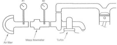
Fig. 14-
So here the odd circumstance exists that flow is down, boost remains the same, and the pressure ratio is higher. Any time the pressure ratio goes up, heat goes up. Net result is that power is down and heat is up. Sounds almost like a Roots blower. This may seem like science or some such, but it's not really. The idea that the turbo is told to make the same amount of boost out of less air logically means it must work a bit harder to do so. The harder it has to work, the more heat it makes. We've all experienced similar situations.
To measure flow losses through the intake system upstream of the turbo, insert a vacuum gauge just in front of the compressor inlet. Then
![]()
Standard barometric
pressure is
Should the gauge read
![]()
Obviously a zero loss is elusive, but the effort to create a low-restriction intake system will be rewarded with more power and less heat. All the same arguments apply to keeping the air filter element clean.
Thermodynamics is not everyone's cup of tea, but the equations are simple, and a fifteen-dollar calculator can solve them. The value in crunching the numbers is to determine whether the turbo is the correct size. The air temperature entering the compressor is vital information, because it is the number from which all others are calculated. Do not assume this temperature is ambient. If the air inlet is outside the engine compartment, compressor inlet temperature may be the same as ambient. If it is in the engine compartment, too often the inlet air is diluted by air that has passed through the radiator or looped around the exhaust manifold. Measure compressor inlet air temperature with a gauge positioned as in figure 14-2.
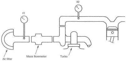
Fig. 14-2. Temperature gauging the intake for determining temperature rise through the turbo. Gauge 1 indicates ambient air temperature available to the turbo. Gauge 2 minus gauge 1 indicates temperature rise across the turbo.
Two quantities must be known at the outlet side of the turbo: pressure and temperature. Compressor outlet pressure is the true boost produced by the turbo. All measurements of the flow as it gets closer to the engine will be referenced to this pressure for flow loss or efficiency calculations. For example, this pressure minus the pressure entering the intake manifold will measure flow loss characteristics of the intercooler and associated plumbing.
Compressor outlet temperature is the other factor required in calculating the turbo size to fit the engine. It is used twice in the equation for IC efficiencies, so measure it carefully. Once pressure and temperature at the compressor outlet are known, the real pressure ratio can be calculated, provided no intercooler is present. With an intercooler, pressure ratio calculation should wait until the intercooler outlet conditions are known.
The most significant calculations to be made here are spot checks of the turbo's efficiency range. The tools for these measurements are not adequate to determine the entire compressor map. Nevertheless, one can develop a feel for whether the turbo is operating in the efficiency range that will get the job done. These calculations are somewhat laborious, but there is no other way, short of calling on a thermodynamics buddy.
At least two spots should be checked: somewhere around torque peak and at maximum rpmboth, of course, at maximum boost. The check involves calculating the efficiency at which the compressor is operating and comparing those numbers to the efficiency predicted by the compressor flow maps.
Compressor efficiency
(![]() ) is calculated using the following formula:
) is calculated using the following formula:
![]()
where
PR pressure ratio
![]() = compressor inlet
temperature on the absolute scale (see glossary)
= compressor inlet
temperature on the absolute scale (see glossary)
Because this is a thermodynamic formula of general applicability, it is necessary to insert the relevant temperature rise in the denominator (from Chapter 5):
![]()
The exponent
The ![]() key on the
fifteen-dollar calculator will allow us to find the value of
key on the
fifteen-dollar calculator will allow us to find the value of ![]() .
.
Example:
Let engine
displacement = 200 cid, boost =10 psi, and compressor inlet temperature =
Using the formula for pressure ratio from Chapter 3,
![]()
Calculation of ![]() at or near the torque
peak:
at or near the torque
peak:
Using the formula for temperature rise from Chapter 5,
Temperature rise =
![]()
Using the formula for airflow from Chapter 3,
![]()
Calculation of ![]() at maximum rpm:
at maximum rpm:
Using the formula for temperature rise from Chapter 5,
Temperature rise =
Then
![]()
Using the formula for airflow from Chapter 3,
![]()
These calculations give the pressure ratio and airflow for two points that can be plotted on the compressor flow map, with pressure ratio the vertical axis and airflow the horizontal axis (see Chapters 3 or 17). Compare the efficiency predicted by the curve on the flow map to the calculated values. If the predicted efficiency is two or three points higher or lower than the calculated values, all is well. If the numbers calculated are four or five points higher than the map, we are in wonderful shape. If they are more than four or five points lower, performance has been compromised, and it's back to the drawing board
Accurate determination of the IC's real capability is in part based on determination of the temperature of the air that cools the cores, Although this factor is not used directly in calculations involving the turbo system, it is of interest in really getting into checking the merit of one core design versus another with respect to heat transfer coefficients.
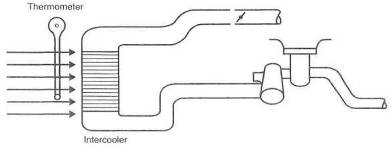
Fig. 14-3. Ambient temperature measurement, necessary for determining intercooler efficiency
Temperature and pressure must be measured again at the intercooler outlet. These numbers are significant, because they are the conditions the engine will experience. This naively assumes that not much will happen in the tube from the intercooler back to the engine. With these data, we have enough information to determine the intercooler's efficiency and the power loss due to boost pressure loss.
Should any significant events occur in the charge's trip from the IC to the intake manifold, they will show up in the intake manifold pressure relative to IC outlet conditions. It is relatively common to have a throttle plate far too small far the job, and here is the way to find it.
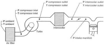
Fig. 14-4. The five points of interest for temperature and pressure measurement
If more than 1 psi difference exists between the IC outlet and the intake manifold, it will probably prove revealing to check the pressure right in front of the throttle plate versus that in the manifold. This will determine if the loss is in the return tube or if the throttle plate is the problem.
The boost gauge in the instrument panel is set up to read intake manifold pressure. This is the amount of pressure you have left of the original pressure created by the turbo less all losses incurred on the way to the intake manifold. Try to keep the total loss under 2 psior, better yet, 10% of the boost pressure.
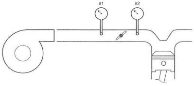
Fig. 14-5. Measuring pressure loss across the throttle body. Gauge 1 minus gauge 2 indicates boost-pressure loss across the throttle plate.
Exhaust manifold pressure can better be described as Turbine Inlet Pressure. This TIP is an evil thing. In the final analysis, I suspect TIP will be called the only evil thing brought to bear by the turbo. The reason TIP is an undesirable quantity is the fact that it is almost always greater than the intake manifold pressure (IMP?) generated by the turbo. When this occurs, a certain portion of the burned exhaust gas is pushed back into the combustion chamber during the cam overlap period. This situation is detrimental to several things, all explained elsewhere in this book.
It is this writer's opinion that a good street turbo system will show the ratio of TIP to IMP to be approximately 2. If a ratio of greater than 2 exists, the turbo is too small and is choking the system down and not permitting much power gain. If the ratio is less than 2, often the boost threshold will be higher than desirable for commuter car use. This situation is offset by the fact that as the ratio comes down, power goes up. In fact, one of the design parameters of a race turbo system is that the TIP/IMP ratio be less than 1. When this crossover point is reached, where intake pressure becomes greater than exhaust pressure, a turbo can begin to make serious power. This is one of the reasons the '87 Formula 1 racers could generate over 1000 bhp from 90 cubic inches. It may came about one day that we can have our cake and more cake again when variable area turbine nozzle turbos are commonplace. They will permit low boost thresholds while allowing boost to exceed TIP once boost has stabilized at its maximum setting.
Measuring turbine inlet pressure requires a bit more effort than other pressure measurements, as exhaust gases are obviously very hot.
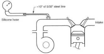
Fig. 14-6. Measuring turbine inlet pressure. The steel line will reduce exhaust gas temperature to silicons hose allowables.
Where do you suppose
the fairy tale started that tailpipe back pressure was needed to prevent burned
exhaust valves? Someone ought to quickly inform all those racers out there that
they are in serious trouble. Tailpipe back pressure can be just as evil as TIP,
but at least it is easy to do something about. Potential gains are more power
and less heat in the systemexactly the right things to achieve. in measuring
tailpipe back pressure, it is also necessary to measure restriction
distribution, as indicated in figure 14-
Tailpipe back pressure is partly responsible for the magnitude of the turbine inlet pressure. Any decrease in tailpipe pressure that can be brought about will be reflected in a nice decrease in TIP.
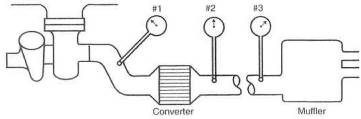
Fig. 14-7. Determining tailpipe restriction distribution. Gauge #1 indicates total tailpipe back pressure. #2 indicates back pressure caused by the pipe and muffler. #3 indicates back pressure caused by the muffler. #1 minus #2 is pressure loss across the converter, #2 minus #3 is pressure loss through the pipe.
Knowing the air/fuel ratio is somewhat like knowing your checkbook balance. It tells you what you've got and where you stand, but not what you can do about it. A wide variety of pieces have recently been introduced to the market for measuring afr.
The neat little oxygen-sensor-based units on the market will give you a good guide, if not exact numbers, but real accuracy has yet to come cheap. For serious tuners, the Horiba and Motec meters are perhaps top of the line. Check the source listings at the end of the book and gather the information to make a reasonable decision.
Measurement of the numbers is nothing more than equipment and time. Evaluation of those numbers is where a bit of experience helps out. When testing, two significant numbers will be required: cruise air and full-throttle afr. Cruise afr will likely be in the range of 14.0 to 15.0 to 1. Full throttle is where the fun is and should be close to 12,5 or 13.0 to 1.
For the home tuner, the oxygen sensor that fits into the tailpipe near the heat source will do a good job. It can be considered a permanent installation and checked as often as desired.
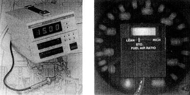
Fig. 14-8. Left: The excellent air/fuel ratio meter from Horiba. While expensive, it offers lab-test-quality results, and its sensor can be mounted at the end of the tailpipe. Right: Although not a lab test instrument, a diode-readout mixture indicator is an excellent low-cost tuning guide.
|
Politica de confidentialitate | Termeni si conditii de utilizare |

Vizualizari: 1049
Importanta: ![]()
Termeni si conditii de utilizare | Contact
© SCRIGROUP 2024 . All rights reserved