| CATEGORII DOCUMENTE |
| Bulgara | Ceha slovaca | Croata | Engleza | Estona | Finlandeza | Franceza |
| Germana | Italiana | Letona | Lituaniana | Maghiara | Olandeza | Poloneza |
| Sarba | Slovena | Spaniola | Suedeza | Turca | Ucraineana |
Bridging Remote Networks
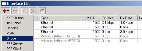
If you have a MikroTik Router with two Ethernet-type interfaces, you can easily put them into one bridge, by
![]() However,
you should be very careful about what are you bridging, because bridge creates
one big broadcast domain, i.e., broadcast traffic is sent over from hosts
connected on one physical interface to hosts on another interface.
However,
you should be very careful about what are you bridging, because bridge creates
one big broadcast domain, i.e., broadcast traffic is sent over from hosts
connected on one physical interface to hosts on another interface.
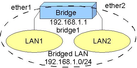
For example, you have two LANs connected to your router with two Ethernet
interfaces. The networks are 192.168.1.0/24 and 192.168.2.0/24, connected to
ether1 and ether2, respectively.

Apparently, you are using routing between those networks, and bridging them
right away how they are wouldn't be such a great idea at all. If you need to
bridge those networks however, you need to change IP addressing. You may
Once you get traffic passed over from one interface to another, you can analyze
it and implement control measures. You can use Torch tool to analyze the
traffic, see all connections, IP addresses, protocols, ports, and traffic speed
used. You can implement IP or MAC address filtering, as well as data rate
management.
Before we proceed with configuration, there is a question for you:
Imagine you have a MikroTik router with three Ethernet interfaces. Interfaces ether1 and ether2 are bridged to monitor traffic between two segments of LAN connected to them. Do you need an IP address assigned to ether1, ether2 or to the bridge interface itself, if you are connecting to the router over ether3, which is on the 10.1.2.0/24 network?
Now lets create a bridge
between ether1 and ether2
interfaces of your MikroTik router to monitor traffic between two segments of
LAN.
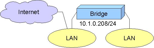
Let us assume you have IP address 10.1.0.208 with /24 bit network mask assigned
to the ether1 interface of the MikroTik router. ether2
interface has no address assigned to it. The default gateway is 10.1.0.1.
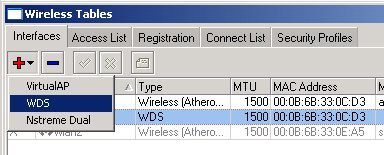
First we should create a bridge interface. In winbox GUI, go to the interface
menu and press '+' button to add an interface, select
'Bridge':
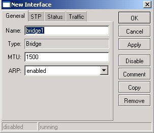
Just click 'OK' to confirm adding bridge interface with name
'bridge1':
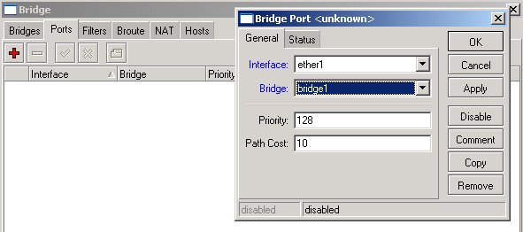
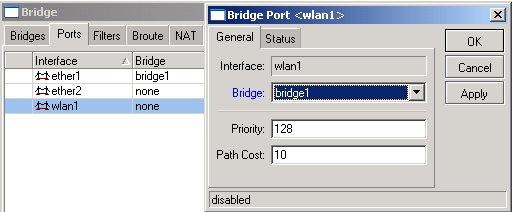
Now you should add interfaces to the bridge. Open up the Bridge menu and select
the Ports tab. All interfaces that can possibly be added to the bridge are
listed there. Double click on ether1 and select bridge1 for the Bridge
argument:
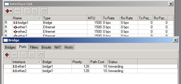
Do the same for ether2, and get the following setup:
If you prefer using command line interface instead of winbox GUI, below are
commands to be issued at the command prompt:
/interface bridge add
/interface bridge port add interface=ether1 bridge=bridge1
/interface bridge port add interface=ether2 bridge=bridge1
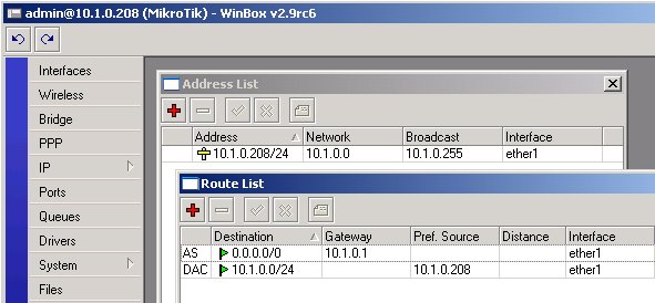
We have created a new virtual interface bridge1 and assigned two
physical interfaces ether1 and ether2 to it. Check the routing
table, it shows bridge1 as the interface for accessing the network
10.1.0.0/24.
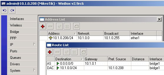
The router can be accessed by the IP address 10.1.0.208 from either side of the
LAN, since the IP address belongs to the bridge interface now. The address move
from ether1 to bridge1 is done internally and it is not reflected
in the address table. If you remove the bridge or just ether1 from it,
the IP address 10.1.0.208 would be reassigned to ether1.
What happens, if you have IP address assigned to the bridge1 interface,
and you remove the bridge interface, i.e., the interface is deleted?
The following types of interfaces can be bridged:
You
cannot bridge any other interfaces types, like synchronous, IPIP, PPTP
PPPoE, and so on. However, you can use EoIP tunnel over those
interfaces to achieve what you need. EoIP works only between MikroTik
routers, it does not work with Cisco and other equipment.
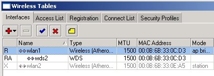
In previous part of the Lesson, we have discussed creating a bridge interface between two Ethernet interfaces. Creating a bridge between Ethernet and wireless interface is very similar. Just remember, that you can bridge only wireless interface, if it is configured to 'mode=ap-bridge', or 'mode=bridge'.
The difference between 'ap-bridge' and 'bridge' is only in number of clients/stations it can register. 'bridge' can register only one station, whereas 'ap-bridge' is limited by the max-station-count only. Level 3 software license is sufficient for wireless 'mode=bridge', but Level 4 license is required for 'mode=ap-bridge'.
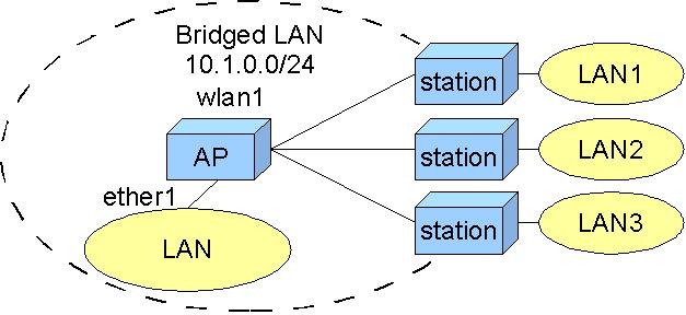
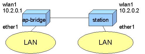
Let us consider the following setup, where we have a wireless AP with ether1
and wlan1 bridged:
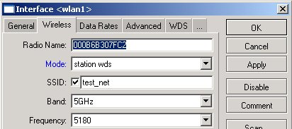
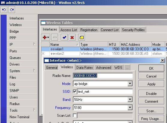
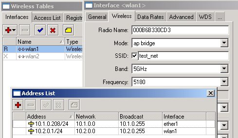
Configure the wireless interface for mode=ap-bridge with ssid=test_net,
frequency=5180
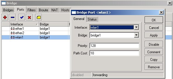
Now you can include the wlan1 interface into the bridge by specifying it under
bridge ports:
Note, that there is only one IP address assigned to the bridged interfaces ether1
and wlan1! The bridged network includes all hosts on LAN where the AP is
connected, and wireless interfaces of the 'stations'. You cannot
extend the bridged network behind the 'stations' in the current
setup.
Further on
we will be creating transparent bridge across wireless
link using WDS. If you do not want to learn about it, you can skip over
to the topic about creating transparent bridge using EoIP.
Jump to the part about using EoIP to bridge remote networks:
Learn about creating encrypted PPTP tunnel and running EoIP over it.
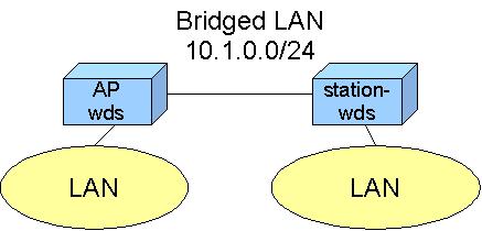
Start learning about using WDS to bridge over wireless
networks:
|
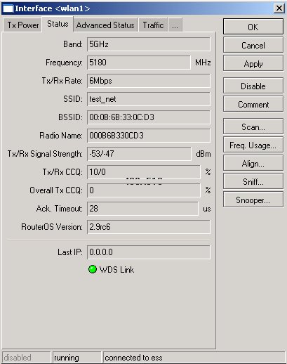
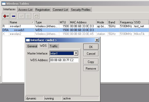
Once the WDS link is established, we can add
interfaces to the
bridges on both sides of the link. We have discussed it at the
beginning of the lesson and you should know how to add a bridge
interface and how to configure bridge ports, i.e., assign interfaces to
it. On both sides we should have 'ether1' interfaces assigned to the
bridge, if they are used to connect the LANs on both sides.
On the AP's side, we add the WDS interface to bridge.

Note
that connection to the router might be lost for a moment, if you are
connecting to it over an interface belonging to the bridge. It is
because the bridge is restarted each time an interface is added or
removed from it.
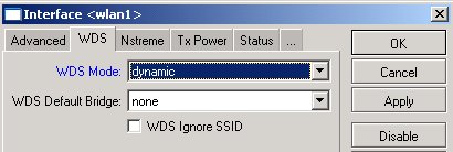
On the station's side, we add the wireless interface, which is in station-wds mode, to the bridge.
Thus
we have created a transparent bridge over wireless link. You can test
it by pinging from a host on one LAN segment over to a host on another
LAN segment. You should use the same address space for hosts on both
LAN segments, including both routers.
Using EoIP to bridge remote networks:
Ethernet over IP (EoIP) is a MikroTik RouterOS
protocol that is used for creating tunnels between two MikroTik routers. The
protocol encapsulates Ethernet frames into IP packets and transports them over
an IP network. EoIP tunnel interface is an Ethernet-like interface and can thus
be bridged. It is widely used for creating transparent bridges between remote
private LANs.
EoIP tunnel is very useful for:
We have previously discussed
creating a transparent bridge between two wireless nodes. We had to use WDS for
that. Now we will see how to create a transparent bridge between two wireless
nodes using EoIP. Note, however, that the EoIP tunnels have greater overhead
than WDS, so it is recommended to use WDS wherever possible.
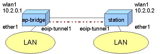
The nodes are configured as routers, the wireless interface of one node is in
ap-bridge (or in bridge) mode
that of the second node is in station mode:

Make sure the link is working, test it with ping from 10.2.0.1 to 10.2.0.2. Next will be creating the EoIP tunnel.
An EoIP tunnel can be created between two
Mikrotik routers once you are able to communicate between them over the IP
network. In our case, there is a point to point wireless link between the
routers. Generally speaking, EoIP tunnels can be created between MikroTik
routers that are interconnected by an IP network (like the Internet) by any
means, for example, one router can be at the head office and connected over
high speed Ethernet to the Internet backbone, the other one might be connected
over and aDSL line in another city or country.
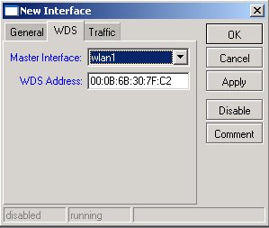
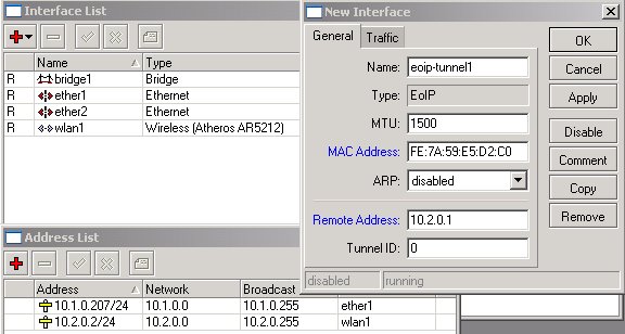
To create an EoIP tunnel between two routers, you should add EoIP interfaces
for it.
EoIP interface is added for
the AP router as follows
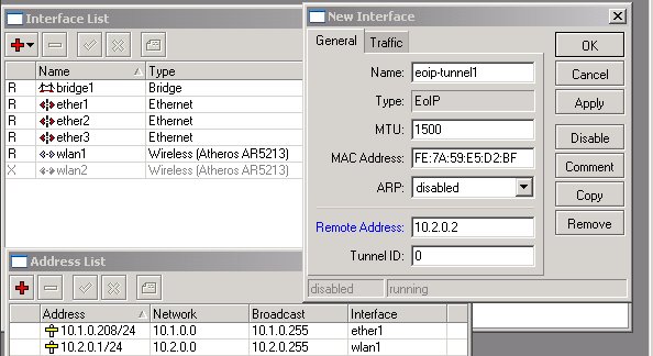
Modify the MAC Address when adding the EoIP interface for the station router:
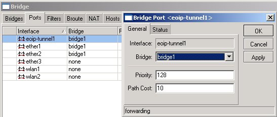
Next, we will be adding the EoIP interfaces to the bridge.
Once the EoIP tunnel has been created, we
need to configure the bridging to make the link 'transparent':
It has been discussed previously how to add a bridge interface and specify
bridge ports. If there is no bridge interface present, just add it to the router.
When specifying bridge ports, make sure to include the ether1
and eoip-tunnel1. You should NOT add wireless interface to the
bridge! For the AP router:
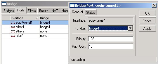
For the station router:
Thus, we have created a transparent bridge over the wireless network using EoIP tunnel. However, the EoIP protocol does not provide encryption. It is not a real VPN without encryption. We need to discuss, how to make it 'secure', so the packets are encrypted when sent over public networks.
Learn about creating encrypted PPTP tunnel and running EoIP over it.
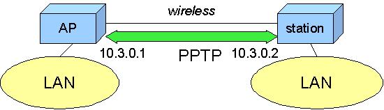
Let us consider the following example, where we have two routers connected over a wireless link:
Our goal is to make the communication between two LAN segments
'secure', i.e., encrypt the data, when it is sent over the wireless
link between two routers. Configuration of the wireless interfaces is the same
as discussed previously, when we were making the EoIP tunnel interface.
We already mentioned that the EoIP protocol does not provide data encryption.
Apparently, we need to use something else to encrypt the data. We can use encrypted
IPPsec, L2TP, PPTP or PPPoE tunnel for that. Once we create the encrypted
tunnel, all data should be sent over that tunnel.
We assume, that the link is configured and running as described previously. Please go back to the previous parts of the course if you need to refresh you knowledge about setting up wireless point to point link.
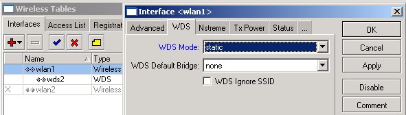
We will be making encrypted PPTP tunnel between the AP and the station (note
that L2TP configuration is the same as for PPTP, just replace 'pptp'
to 'l2tp' in all configuration strings). One unit should be PPTP
server, and the other one should be PPTP client. It does not really matter
which one is the server.
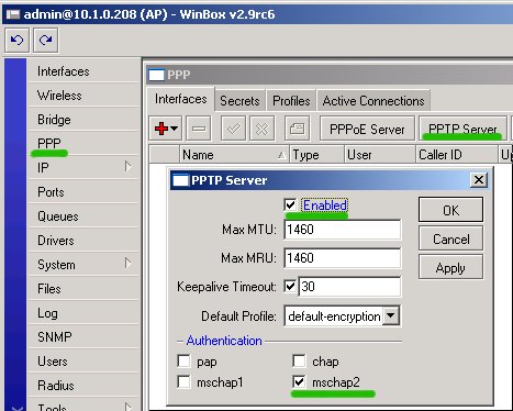
To start PPTP server, open up PPP menu, select PPTP Server and check
the Enable box. You may want to have default profile with encryption
and leave only mschap2 for authentication (note that PAP and CHAP
authentication protocols do not support encryption, and MS CHAP version 1 has
security flaws, the second version was designed to fix; that is why it is
recommended to only use MSCHAP version
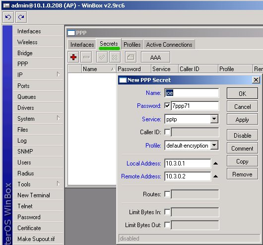
Next, open up the Secrets tab in the PPP window and add authentication
information for ppp client:
Add the PPTP client interface at the other router. Select PPP from the main menu and click '+' to add PPTP Client, specify:
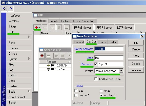
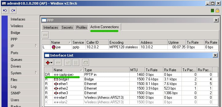
Click 'Apply' and check status of the added interface
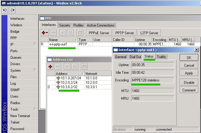
We see, that an encrypted PPTP link has been established and IP address
10.3.0.2/32 has been assigned to the pptp client interface pptp-out1.
Check the status of PPP connections on the server (AP)
Next, we are going to make EoIP tunnel over the established PPTP tunnel. If you
do not require bridging of the remote networks, you do not need the EoIP
tunnel. All you have to do is make sure the routing sends packets from one
network to the other one over the encrypted link, i.e., gateway should be the
remote IP address on the tunnel interface (10.3.0.1 or 10.3.0.2), not on the
wireless interface (10.2.0.1 or 10.2.0.2).
We have the PPTP tunnel established
between two routers.
Next, we need to add the EoIP tunnel between the routers in such a way
that it goes over the encrypted tunnel. It is very similar to what we
did previously, when the EoIP tunnel was made directly over the
wireless link.
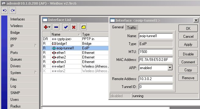
Add the EoIP interface on the AP side
Add the EoIP Tunnel interface on the station:
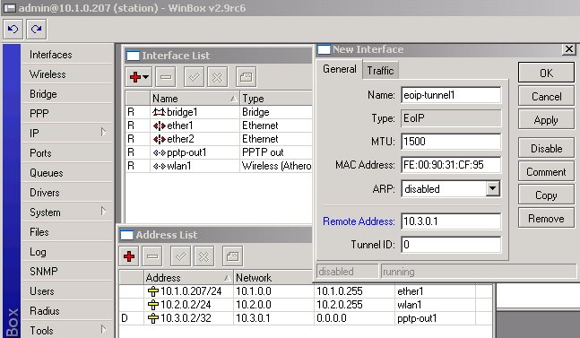
Note, that we have specified IP addresses of the encrypted tunnel interface rather than the IP addresses of the wireless interface when creating the EoIP tunnel.
All we have to do now is to include the eoip-tunnel1 interface into the bridge1.
We have done this before. Add the bridge interface, if you do not have it
already. You should:
This should be done both on the AP and on the station units.
Thus
we have created a transparent bridge between two LAN segments. All
traffic between the segments is passed over the encrypted tunnel making
this connection 'secure'.
|
Politica de confidentialitate | Termeni si conditii de utilizare |

Vizualizari: 1619
Importanta: ![]()
Termeni si conditii de utilizare | Contact
© SCRIGROUP 2024 . All rights reserved