| CATEGORII DOCUMENTE |
| Bulgara | Ceha slovaca | Croata | Engleza | Estona | Finlandeza | Franceza |
| Germana | Italiana | Letona | Lituaniana | Maghiara | Olandeza | Poloneza |
| Sarba | Slovena | Spaniola | Suedeza | Turca | Ucraineana |
How to configure Litespan 1540 in Tellas network
STEP 1:
Make a connection to a Litespan 1540 using a RJ11/DB9 cable (see next figure) connected to TAUP plug (Litespan 1540) and RS232 port (Laptop).

Use the craft terminal ALCATEL FR2.6 CT21.5.0 NE21.5.3 .

The server name for all Litespan 1540 equipments is: 192.0.0.5

STEP 2:
After establish a connection with the litespan equipment go to menu:
SW Management -> Download -> Perform in order to download and activate the new software realease in FR 2.6 with greek signaling 21_5_4a
Select software version you want to download (in this case 21.5.4a) and check the Forced Download checkbox.
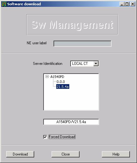

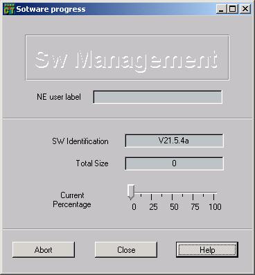
After confirming you must wait almost 15 minutes until the software download to the second memory bank of NEHC controller is done.
Go to menu SW Management -> Display, Modify, check the 21.5.4a version, right click on it and press ACTIVATE in order to became the active software version.
In this moment the equipment will reset (warm restart).
After restart the new software version will be in UNDER_TEST mode and the older software version will be in ROLL_BACK mode (if the new version of software fails you can restore the old one)
In order to have only one software version ACTIVE&COMMITED go to
SW Management -> Display, Modify, check the 21.5.4.a (UNDER_TEST) version, right click on it and press COMMIT.

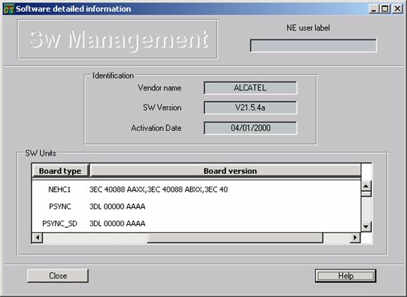
If you want to see detailed information about the new software version 21.5.4a go to
SW Management -> Display, Modify, check the 21.5.4a (ACTIVE & COMMITED) version, right click on it and press Detailed Information
STEP 3:
Make minimal configuration: Administration ->Installation Data
The specific installation data can be verified or changed by selecting Administration ->
Installation data. The system will ask for a password. By default, password is space bar. If the password is correct, the Installation data window is opened
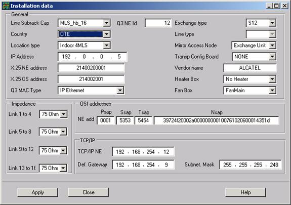
The following fields : Q3 NE Id, TCP/IP NE, Def. Gateway and Subnet Mask will be modified (distinct on each Litespan 1540 equipment) according to project specifications.
Country field OTE specify greek signaling (customer profile data).
Q3 MAC Type field IP Ethernet specify Network Management type.
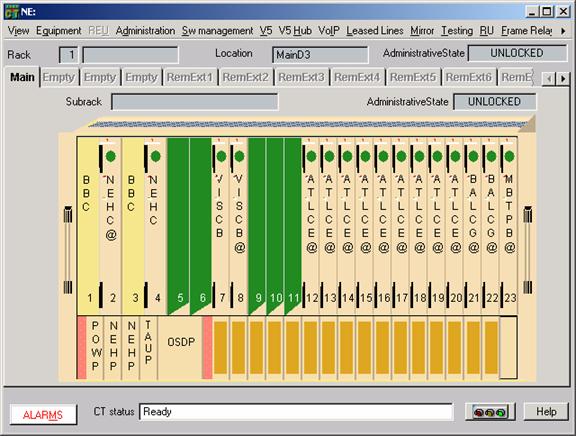
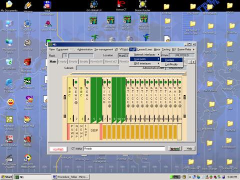
STEP 4:
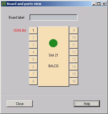
Plug all the boards and declare them using craft terminal.
STEP 5:
Choose the switch-over mode (hot switch-over or warm switch-over):
Equipment -> V5SwitchOverMode
The system will ask for a password. By default, password is space bar.
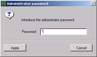
If the password is correct, the Switch over mode window is opened
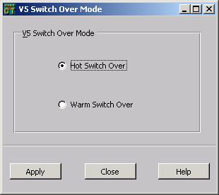
When a switch-over occurs from an active to a redundant NEHC controller if Hot Switchover flag is enabled, VISCB card is not reset so calls progress with the same quality, except for the calls set up during the switchover (matrix crossconnection in NEHC may become unavailable during a few moments).
When a switch-over occurs from an active to a redundant NEHC controller if Hot Switchover flag is disabled, all the cards in the NE are initialized and the interfaces started up again, VISCB card is reset and starts downloading from NEHC when this later is again up and running. VISC eventually is ENABLED and performs a ServiceChange registration to its primary MGC. Traffic is recovered when VISCB comes in service at the end of its start up.
STEP 6:
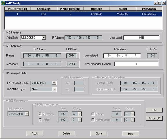
Declare a Media Gateway Interface: VoIP -> Network Interfaces -> Declare.
After declaring the MGI interface in order to start up
is mandatory to put
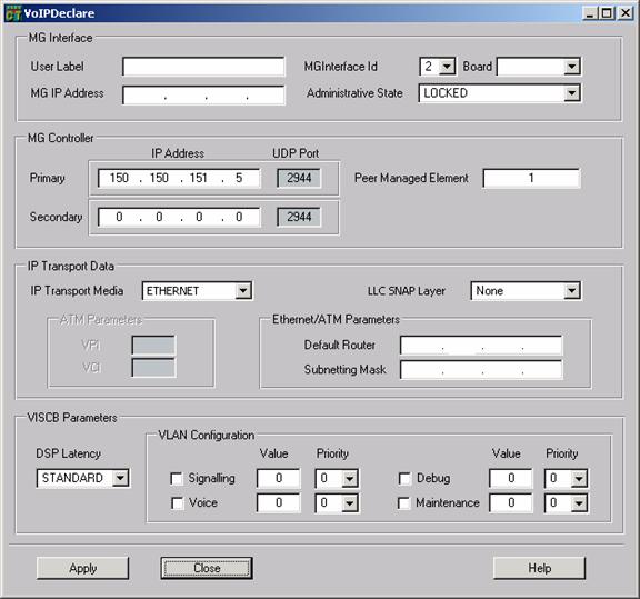
MGI has the following attributes:
MGInterfaceId This field is the internal identifier of the MG interface. The operator has to select it from a list of free internal identifiers. The values range from 1 to 4.
adminState, it is used to initiate/stop the communication with the CLS (Call Server) and the reporting of alarms, the communication is initiated by the MG, default value is locked. It is also used to allow/disallow the switchover of an active VISC to an standby card. When the adminState is locked, the switchover for this MGInterface is disallowed, when it is unlocked it is allowed.
Board The operator can select the board where the MG Interface is located from the list of all of the declared VISCs. This field can be previously filled depending on the way this window is reached. Selectable boards are presented as: VISC <slot number>.
associatedMgcIP, IP address of the current associated CLS (or MGC), it is 0.0.0.0 before to contact with CLS
associatedMgcPort, UDP port for MEGACO of the current associated CLS, it is 0 before to contact with CLS
clientUserPorts, it provides the list of associated user ports, default value is emptyset
ipTransport, it can be: Ethernet, ATM (VISCA only)
lLCSNAPLayerPresence, it has the following possible values: none and routed. This attribute is used to activate the transmission of the LLCSNAP header.
mgIP, IP address for voice and signaling of the VISC
mgSubnettingMask, IP subnetting mask for voice and signaling of the VISC. Note
that this attribute is needed not only in case of ethernet transport, but also in case of bridged ATM too (VISCA only).
mgNextHop, IP address of the default router. It is needed in case of ethernet and also for bridged ATM (VISCA only).
operationalState, it provides the operational state of MG, by default is enabled. It is disabled in case of VISC card failure, if CLS is unreachable or by dependency in case of locking the VISC.
primaryMgcIP, IP address of CLS (or MGC) master.
primaryMgcPort, UDP port for MEGACO of CLS master, by default is 2944
secondaryMgcIP, IP address of CLS backup. CLS backup is used only when master is unreachable, by default is 0.0.0.0.
secondaryMgcPort, UDP port for MEGACO of CLS backup, by default is 2944
peerManagedElement It is a number field where the operator has to introduce the number of the Media Gateway Controller connected via this MG interface. The values range from 0 to 65535.
supportingVci (only applicable to VISCA), VCI of ATM PVC for voice/signalling that supports the connection of the VISCA to IP network (external router). It is only needed in case of ATM. Since this attribute is applicable to VISCA only, it must be greyed out when the MGI is associated to a VISCB.
supportingVpi (only applicable to VISCA), VPI of ATM PVC for voice/signalling that supports the connection of the VISCA to IP network (external router). It is only needed in case of ATM. Since this attribute is applicable to VISCA only, it must be greyed out when the MGI is associated to a VISCB.
userLabel, friendly name for Operator, by default null.
dspLatency (only applicable to VISCB), selects DSP working mode for G.711. Two values are possible: low and standard. This attribute is settable by the operator when the card is locked. Since this attribute is applicable to VISCB only, it must be greyed out when the MGI is associated to a VISCA.
vlanConfiguration (only applicable to VISCB), contains the VLAN ID and VLAN priority for the different traffics. The vlanConfiguration parameter is the sequence of 4 possible VLAN parameters (for signalling, voice, debug, maintenance). VLAN parameters are optional. Each VLAN parameter is made of the VLAN value (integer from 0 to 4094) and the priority (integer from 0 to 7), settable by the operator only when the MGI is locked; Since this attribute is applicable to VISCB only, it must be greyed out when the MGI is associated to a VISCA. VLAN tags are optional for all traffics. VLAN ids can be shared by some or all of the four defined traffics.
STEP 7:
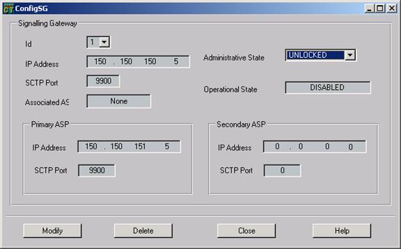
Declare a Signaling Gateway Interface (ISDN-BA):
VoIP -> Network Interfaces ->ListModify -> SG
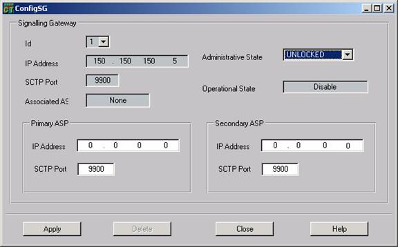
The attributes of the signallingGateway are:
signallingGatewayID is the unique identifier of an instance of the signallingGateway managed object class. This value is the same sa the one of the media gateway.
signallingGatewayIPAddress indicates the IP address of the signalling gateway in VISC. This value is the same as the one of the media gateway .
signallingGatewaySCTPPort indicates the local SCTP port of the SIGTRAN signalling gateway. Its value is 9900.
primaryASPIPAddress indicates the IP address of the primary Aplication Server (AS). By default, its value is 0.0.0.0.
primaryASPSCTPPort indicates the SCTP port of the primary ASP. By default, its value is 9900. This is the assigned port for IUA for SCTP, UDP and TCP (see RFC 3057: ISDN Q.921 User Adaptation Layer).
secondaryASPIPAddress indicates the IP address of the secondary ASP. By default, its value is 0.0.0.0.
secondaryASPSCTPPort indicates the SCTP port of the secondary ASP. By default, its value is 9900. Secondary AS attributes are used by the signalling gateway when trying to contact the backup AS after a failure of the primary one.
associatedASP indicates the active ASP. Everytime the active ASP changes, the NE must send an AVC to communicate the change to the management system. Possible values are: none, primary, secondary, loadsharing. Default value is none . (in case of loadsharing, there could be several active ASPs at a time).
administrativeState with default locked.
operationalState with default enabled.
STEP 8:
To declare VOIP User Ports (PSTN or ISDN-BA) you must select:
VoIP -> User Ports -> Declare
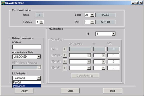
Select Subrack, Board and Port where you want to create the subscriber. Also you must complete the address for the subscriber and also the PSTN Special Features (Direct Dialling, Public Phone ) and Administrative state (UNLOCKED - enabled LOCKED - disabled)
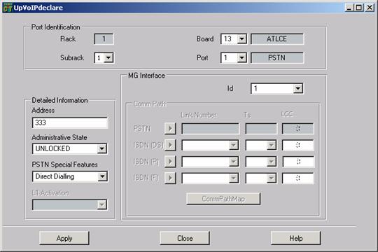

For ISDN BA subscribers voipL1Activation, has two values (PerCall layer 1 is activated only when initiating a call Permanent layer 1 is activated all the time). The default value is PerCall. This parameter is not applicable to V.5, so OS/CT only will make it visible when an ISDN BA port is assigned to a MGI.
ATTENTION ! EFaddress for ISDNBA over VoIP (Address field) are restricted to 0 to 255 in Litespan. If freedom of choice were allowed, the maximum datagram size could be exceeded since many interface identities should be individually listed at IUA level, instead of being declared in a single field as a range.
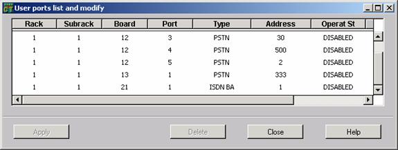
If you want to check all the subscribers declared previously go to
VOIP > User Ports -> List Modify
ANNEX 1: Alarms
The following alarms are related to the VoIP service:
mediaGatewayInterface object has a communication alarm with mediaGatewayControllerUnreachable as probable cause.
PSTN ports have the following associated alarms in VoIP:
communicationsProtocolError/portControlProtocolTimeOutError (Minor) subscriber declared in MG and not declared in MGC. Check L3 address between MG and MGC
terminationIdMismatch (Warning) Address mismatch
ISDN-BA ports have the following associated alarms in VoIP:
communicationsProtocolError/isdnLayerActivationFault (Warning) - Connect NT at subscriber side. Perform electrical tests at subscriber side for determining the fall point. Perform ISDN Quick Test (layer 1 activation).
communicationsProtocolError/portControlProtocolTimeOutError (Minor) subscriber declared in MG and not declared in MGC. Check EF address between MG and MGC
powerProblem (Warning) - Check cabling. Perform electrical and line tests to see if is not a short circuit on subscriber line.
terminationIdMismatch (Warning) Address mismatch
accessEquipment object has the following alarms:
corruptData: error in the loaded Sw package.
dspFail: a HW malfunction is detected in a DSP.
ethernetFailure: reported by the VISC card if Ethernet has been selected as IpTransport
for any MGI in the NE, and ATM has not been selected as IpTransport for the MGI (if configured
by Operator) associated to this card. Otherwise, (ATM selection for IpTransport) the
alarm although detected is not reported from VISCA SW application. One NEHC control
SW receives such alarm the VISCA managed object is set to disabled operational state.
plugNotDetected: reported when switchoverMode is hot and the card does not detect
the VISPA plug.
replaceableUnitFail: sent if a HW failure is detected as startup.
|
Politica de confidentialitate | Termeni si conditii de utilizare |

Vizualizari: 6572
Importanta: ![]()
Termeni si conditii de utilizare | Contact
© SCRIGROUP 2024 . All rights reserved