Abstract—
Harmonic current originating from electric locomotives can
be magnified due to the impedance characteristics of power supply circuit and
bring about various problems. That is, electromagnetic interference with
communication lines, operational trouble in signaling, overheat and/or
vibration in power capacitor, malfunction in protection relay and so on.
Therefore, the exact assessment of the harmonic current flow must be undertaken
at designing and planning stage for the electric traction systems.
For these reasons, we proposed a new approach to
model and to analyze traction power feeding system focused on system response
to current and voltage harmonic. Moreover, harmonic characteristics in electric
train depend on its operational modes. Therefore, Measurements of harmonics are
performed on the real railway power supply systems under normal operation. The
spectrum and distortion analyses in measurement data are variously described in
this study.
Keyword: Electrified Railway System, Harmonic
Generation, Harmonic Analysis
I.
INTRODUCTION
The harmonic current happened in the electric
train is resonated at the specific frequency by the impedance characteristic of
the power supply system. The resonance causes the amplification phenomenon of
the harmonic current and various problems.
The harmonic current make
interference in the adjacent lines of communications and the railway signaling
system. Furthermore, in case it flows on the side of power system, overheating
and vibration at the power capacitors are caused. Also, abnormal operation at
the protective devices can occur.
Therefore,
we need to evaluate harmonic problems accurately in planning step to construct
new electric railway system
In reference to this study, we showed how the system
respond to the harmonics originated from electric train. That is, the system
response to the harmonics was derived by computational algorithm with numerical
formulas in theoretical aspects. However, the real catenary system has complex
configuration of conductors. it is an important point that we can consider the
circuit element of catenary conductors as uniformly a distributed RLC element.
Moreover, harmonic characteristics of electric train depend on its operational
modes [1].
From this point of view, measurements of harmonics
are performed on the real railway power supply systems under the various
operational modes. The spectrum and distortion analyses in measurement data are
variously described in this study.
II.
Measurements and analyses of harmonics
We analyzed the
measurement data of the harmonic current on the test track of the high-speed
railway system for the field test. The field test was performed in the KTX(Korea Train Express
) and in the substation (Shinchungju)
2.1 Characteristic of power consumption
of KTX
The characteristics of the
power consumption of the KTX and the characteristics of the harmonic occurrence
are tested in the KTX. The voltage is the potential difference between the
pantograph and the rail. The current is measured through the CT of the circuit
that supply the current to 3 Motor Blocks. In case operating whole 6 Motor
Blocks, we regard double of measured current value as the whole current of the
KTX.
The detailed results of the
power consumption by the speed of the KTX are shown in Fig 1.
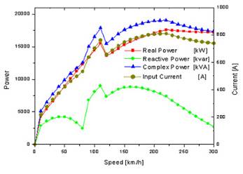 Fig.
1 Characteristic of power consumption of KTX
Fig.
1 Characteristic of power consumption of KTX
The
power consumption of the KTX is locally peaked at about 100km/h in Fig 1. And
the whole peak power consumption is max at 200km/h. The special characteristics
of the curves appear at about 100km/h. The phenomenon is due to the additional
injection of the PFC(Power Factor Compensator).
2.2 Harmonic characteristic of KTX
(1) Test condition
The power car of the KTX was put in the end section
to measure the harmonics occurred from the KTX. We operated whole 6 Motor
Blocks and recorded the characteristics of the harmonics. The KTX was isolated
from the adjacent power system. We dontt have to consider line impedances and
capacitances of the catenary system. Therefore, the whole circuit is as
following.
Power utility - transmission line - main transformer
- auto transformer - KTX.
The test condition is shown in Table 1. B1, B2, B3
and B4 are the combination of the size of Motor Block and the state of
injecting the PFC.
(2) Result
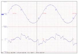
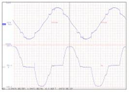
The measured waveform of the voltage and the current
is illustrated in Fig 2~5 under the test condition of B1~B4. In case the PFC is
off, Fig 4 shows that the current includes especially much harmonics at the low
frequency.
Table 1. Test condition for
measuring harmonic characteristic of KTX
|
No.
|
Test condition
|
|
B1
|
6MB PFC:On (2/MB)
|
|
B2
|
6MB PFC:On (2/MB)
|
|
B3
|
6MB PFC:Off
|
|
B4
|
3MB PFC:On (2/MB)
|
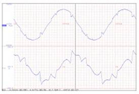
Fig 2. Waveform of voltage(up) and
current(down)-B1
Fig
3. Waveform of voltage(up) and current(down)-B2
III.
Measurement and
analysis of system response characteristic
We define the amplification of the harmonic
current. The harmonic current is amplified by the parallel resonance. The
parallel resonance is occurred by the capacitive reactance of the catenary
system and the inductive reactance of the substation. That is, the
amplification of the harmonic current, m(k), is calculated as the ratio of the
current injected into the substation over the current occurred from the
electric train [2].
m(k) = ISS(k)/ Ipanto(k)
where,
m(k) : the amplification of harmonic
current at k frequency
ISS(k) : k frequency current
injected into the substation [A]
Ipanto(k) : k frequency
current occurred from the electric train [A]
The location of the
substation is at 129km from the specific point. The end of the catenary is at
108km from the specific point. So, the substation feeds the power from 129km to
108km.
The test conditions are as
follows.
- The KTX is located at two spots, which
are 129km and 108km.
- The system feeding the power to the
catenary is on/off.
-The size of the Motor Block is changed.
Fig
4. Waveform of voltage(up) and current(down)-B3
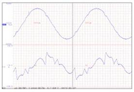
Fig
5. Waveform of voltage(up) and current(down)-B4
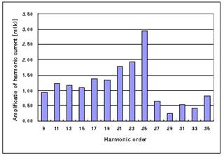
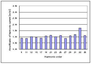 Fig 6. Amplification of harmonic current
(129km,
6MB, Power-Off)
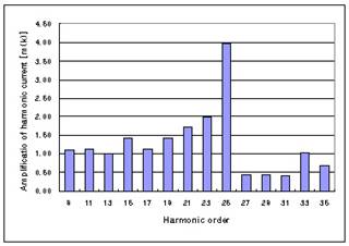
Fig
8. Amplification of harmonic current
(129km, 3MB, Power-On)
The amplification of the harmonic current is shown
in Fig 6~9.
In
case the system feeding the power to the catenary is off, the phenomenon of the
amplification of the harmonic current is not so obvious(Fig 6).
In
case the system feeding the power to the catenary is on, the harmonic resonance
is appeared at 25th harmonic order. When the KTX is located at
129km, the amplification of the harmonic current is about 4 or 5 times higher
than it that the KTX is located at 108km.
IV.
Measurement and
analysis of THD depend on KTXts operational modes
We
execute the running test of the one KTX to investigate the THD(Total Harmonic
Distortion) limited at PCC(Common Coupling Point) and measured harmonics at the
154kV bus of the substation.
According
to the running patterns of the KTX, which are 3 modes of acceleration, maximum
speed and regenerative breaking.
Fig
7. Amplification of harmonic current
(129km,
6MB, Power-On)
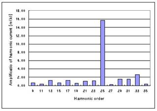 Fig 9. Amplification of harmonic current
(108km,
6MB, Power-On)
The spectrum of the harmonic voltage and the
harmonic current are illustrated in Fig 10~12.
Also,
the THD in time domain is shown in Fig 13. The THDs in 3 modes of the running
pattern are different.
In
Fig 10~12, while the harmonics of 3rd ~ 5th, 15th
~19th are high remarkably in the acceleration mode. The harmonics of
3rd ~21st are high in the regeneration mode.
Also,
the harmonics of the acceleration mode and the regeneration mode are higher
than those of the maximum speed mode.
For
this reason, Fig 13 shows the results that the THDs of the acceleration mode
and the regeneration mode are higher than those of the maximum speed mode.
V.
CONCLUSION
In the real electric railway system, the results of
the measurement of the system response characteristic and the harmonics are as
follows.
(1) In case the
system feeding the power to the catenary is off, the phenomenon of the amplification
of the harmonic current is not so obvious(Fig 6).
In
case the system feeding the power to the catenary is on, the harmonic resonance
is appeared at 25th harmonic order. When the KTX is located at
129km, the amplification of the harmonic current is about 4 or 5 times higher
than it that the KTX is located at 108km.
(2) In spite of the
condition that the running KTX is one, the measured maximum THD is 1.8%. The
THD exceeds the limitation of 1.5% at the PCC.
(3) The THDs of
the acceleration mode and the regeneration mode are higher than those of the
maximum speed mode.
References
[1]
Korea Railroad
Research Institute,
tEvaluation of Power Quality In Seoul-DaeGu High-speed
Railway(),t 2002.
[2]
Yoshifumi Mochinaga, tHigher Harmonics
Resonance on AT Feeding Circuit and Countermeasures to Suppress it,t T.IEE Japan, Vol.
114-D, No. 10, 1994
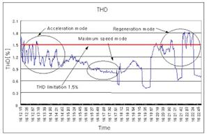
Fig. 13 THD
in 3 running patterns of KTX