| CATEGORII DOCUMENTE |
| Bulgara | Ceha slovaca | Croata | Engleza | Estona | Finlandeza | Franceza |
| Germana | Italiana | Letona | Lituaniana | Maghiara | Olandeza | Poloneza |
| Sarba | Slovena | Spaniola | Suedeza | Turca | Ucraineana |
Hi-Fi Preamplifier Rod Elliott (ESP)
![]()
![]() PCBs
are available for this project - Please click the image for details (Rev-A
boards now shipping)
PCBs
are available for this project - Please click the image for details (Rev-A
boards now shipping)
Introduction
A complete hi-fi preamp including tone controls (and with provision for PCB mounted pots) is something I have avoided, since the pots that are available in different parts of the world are not necessarily compatible. Due to demand, this project has been developed (along with a complete PCB) to fill the gap in the lineup available from ESP.
The preamp featured is very straightforward to make on the PCB, and has an innovative tone defeat function. Rather than completely disable the tone controls, they are massively de-sensitised, and when 'defeated' have a maximum range as shown in Fig. 3 (below). This can be increased if desired, so you can have two tone control settings, one with the normal 10dB boost and cut, and the other with a very subtle 3dB boost and cut - this will be enough (surprisingly) for very minor adjustments such as you might need for day-to-day listening.
Otherwise, the design is fairly conventional, with the main advantage over other designs being that there are almost no wires to run. Source switching is done any way you like - I suggest a rotary switch at the rear of the enclosure, and an extension shaft to bring the shaft to the front. This results in the minimum of wiring, and reduces crosstalk from other active inputs.
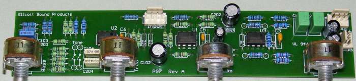
Photo of Completed
Revision-A Board
As you can see, the PCB is very compact. The volume pot is actually spaced a little further apart than the others to allow a larger knob, since this is the most commonly used control in any preamp. The use of 16mm pots makes for a small and neat layout, and makes it very easy to include the preamp with a power amp, making a complete integrated amplifier system.
Note that the Rev-A board is slightly different from the Rev - circuitry shown here. The differences are not great, but you do need the info in the secure site to see where the various parts are located.
Description
The input stage is configured as shown with a gain of 2 times (6dB), and also acts as a buffer for the tone control circuit. The tone control is a basic Baxandall type, but the addition of R117, 118 and 119 provide flexibility and easy reconfiguration that is not available with the traditional arrangement.
R119 is the tricky part in this circuit (which is unique, by the way - I have not seen this technique used before). As shown it is 100k, and this limits the tone control range to a sensible +/-10dB. To obtain more boost and cut, R119 (and R219) may be omitted altogether. Conversely, reducing the value will give a smaller range, with about 6dB at 20Hz, and 7.5dB at 20kHz with 22k.
Figure 1 - Input and Tone
Controls
The tone control (and overall) performance is shown in Figure 2 (10% steps of the pots), and it can be seen that the midrange is barely affected. This is in contrast to the majority of designs, where the controls are centred on 1kHz, and there is a very audible effect in the midrange frequencies. For those who absolutely do not want to use tone controls, I suggest the DoZ preamp (Project 37) or Project 88 - both were designed with no tone controls and are more in the line of true minimalist designs.
Figure 2 - Frequency
Response (SW1 Open)
By contrast, Figure 3 shows the tone control range when SW1 is closed. This also means that when the controls are centred, any minor deviation (due to pot tolerances) is minimal, and response is completely flat (within 0.1dB). As you can see, the variation is much smaller, and it is probable that this setting will be the only one used most of the time.
Figure 3 - Frequency
Response (SW1 Closed)
In Figure 3, the curves are shown for maximum, 75%, 50% 25% and minimum settings of the tone controls. The treble response is more pronounced than bass, but is still limited to a maximum of +/-3dB at 20kHz. Overall, The circuit has excellent flexibility, and will suit normal 'rumpus room' duties just as readily as it will suit the listening room. Balance, volume and output stages are shown below

Figure 4 - Balance, Volume
and Output Stage
The balance control is deliberately designed to have very little effect around the central position, as this makes precise positioning much easier. The volume control uses a linear pot, and overall system gain is about 0dB with the pot in the '12 o'clock' position. Maximum gain is 13dB, and the volume control uses a modified version of Project 1's 'Better Volume Control' to obtain a log response. Output impedance is 100 ohms, and using the suggested 2.2uF polyester cap, the preamp will drive a 22k load with overall response as shown in figures 2 and 3. Low frequency cutoff is about 3Hz with a nominal 22k load. A higher value may be used for C103/203 if desired, but it is expected that the value shown will be quite sufficient for all normal power amplifiers.
The final stage is inverting - this is to correct for the inversion in the tone controls, and brings the overall phase back to normal. Again, this stage runs with a nominal gain of 6dB, although this varies as the volume pot is adjusted. Lowest noise is obtained at a middle setting of VR4 - the general area where the pot will be used the most.
Where it is found that the gain is excessive, R114/214 can be reduced in value - with 15k resistors, gain of this stage will be reduced to unity (probably too low), and a sensible compromise would be 22k. It depends on the input sensivity of the power amplifier of course, so this is left up to the reader to determine after some initial tests. Additional holes are provided in the PCB to allow you to reduce the gain without having to remove the existing resistors should that be found necessary.
The final figure shows the opamp bypass components - ceramic 100nF caps and 10uF electros are used for RF stability as usual. These are essential, and especially so where high speed opamps are used.
Figure 5 - Supply Bypass
Components
Electros should be rated at 50V minimum, as should the ceramics. Multilayer bypass caps are essential here, do not use polyester bypass caps, as their HF performance is simply not good as ceramics. They may be satisfactory for use with TL072 opamps, but ceramics are better.
Construction
Note that although shown using TL072 opamps, OPA2134 or anything else that suits your purposes may be used instead. I do not recommend using anything less than a TL072, even for the workshop or rumpus room, as there will be excessive noise and limited frequency response - this in turn limits the usefulness of the preamp.
|
|
The standard pinout for a dual opamp is shown on the
left. If the opamps are installed backwards, they will almost certainly
fail, so be careful. |
Remember that the supply earth (ground) must be connected! When powering up for the first time, use 100 ohm to 560 ohm 'safety' resisors in series with each supply to limit the current if you have made a mistake in the wiring.
If the PCB is used, construction is a snap. As usual, all construction notes, Bill of Materials and recommended layouts will be available shortly. If you choose not to use the PCB, wiring is a little more challenging, since there are quite a few parts, and some wiring routing is reasonably critical if excessive crosstalk and oscillation is to be avoided.
All resistors should be metal film, and preferably 1% tolerance for best channel matching and noise performance. Likewise, the capacitors for the tone controls should be matched as closely as possible, using a capacitance meter. The pots are all linear, and for the PCB, you will need PCB mount 16mm pots, as these are reasonably common everywhere.
Power requirements are not critical, but the P05 power supply is recommended to maintain low noise. Power should be +/-12 to +/-15V, with the higher voltage giving the best headroom. As shown, it will be virtually impossible for any standard input signal to clip the input or tone control stages.
Finally, Figure 6 shows a fairly typical input switching system - nothing flash, but very functional. As mentioned above, a rotary switch at the rear of the case is recommended to minimise wiring and to make assembly as simple as possible.
Figure 6 - Input and
Switching Suggestion
Any of the additional inputs (or the tape outputs) can be omitted if not needed, but since dual (stereo) rotary switches are typically 6 position, it makes sense to use all positions if possible. For the relatively small cost of the extra RCA connectors, you will have enough inputs to allow for future additions to your system. The phono preamp is naturally optional - there is no reason to include it if you don't have a turntable or any vinyl discs in your collection.
|
Politica de confidentialitate | Termeni si conditii de utilizare |

Vizualizari: 5056
Importanta: ![]()
Termeni si conditii de utilizare | Contact
© SCRIGROUP 2024 . All rights reserved