| CATEGORII DOCUMENTE |
| Bulgara | Ceha slovaca | Croata | Engleza | Estona | Finlandeza | Franceza |
| Germana | Italiana | Letona | Lituaniana | Maghiara | Olandeza | Poloneza |
| Sarba | Slovena | Spaniola | Suedeza | Turca | Ucraineana |
To open this discussion on lightwave transmission, let's ask a simple question:
When did we begin to use lightwaves to communicate?
Well, the answer is C or D, depending upon where you stand on the argument among anthropologists of whether Homo sapiens descended from the Australopithecus species. For our purposes, let's just say we've been communicating by using lightwaves for a long, long time.
We communicate by lightwaves every waking hour of every waking day, even if we don't consciously think about them. On a very basic level, if a person waves to you, it is the reflection of lightwaves off that person's hand that your eyes detect. And we know at a glance whether the person is friendly or threatening by checking the lightwaves to see whether the hand is open or clenched in a fist.
In ancient times, Greeks and Phoenicians used reflected light from mirrors to communicate by code between watch towers, army generals used mirrors to signal troop movements, and ship captains used both mirrors and lanterns to communicate with their fleets.
During the American Revolution, General George Washington's troops used bon fires to signal the movement of British troops, and even today, military ships still use high-powered lights to exchange instructions when they don't want to break radio silence.

Alexander Graham Bell's 1880 photophone.
Alexander Graham Bell, who triggered the communications revolution with his invention of the telephone, developed in 1880 the 'Photophone,' using mirrors that vibrated from the pressure of the speaker's sound waves. The vibrating light signals from the mirrors were transmitted through the atmosphere to a photocell in a phone receiver, which in turn was connected to an electric current that powered a speaker.
All early lightwave communication systems, including the Phoenicians' and Mr. Bell's, had two major drawbacks:
|
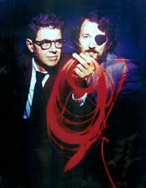
Above, researchers Charles Townes (left) and Arthur L. Schawlow develop the theory of the laser in 1958. |
A number of Bell Labs engineers tried to get around the challenges of weather and line-of-sight problems by developing waveguides, tubes with mirrors that would protect the signals from interference and deflect them so they could travel around bends. The designs were challenging but economically impractical, and none of the early waveguide systems could effectively and economically compete with electrons traveling over copper cable.
All that
began to change in 1958 with the development of the laser by two
scientists at Bell Labs, researcher Arthur Schawlow and a consultant
from
Now they only needed a satisfactory medium by which to transmit this light.
 Glass seemed a good choice, since we've been using it
to see through for centuries. However, turn a piece of glass on end and try to
look through it. You'll be disappointed because the end will be opaque green,
due to the presence of copper, manganese and other minerals. Indeed, regular
window glass becomes opaque within less than an inch of depth.
Glass seemed a good choice, since we've been using it
to see through for centuries. However, turn a piece of glass on end and try to
look through it. You'll be disappointed because the end will be opaque green,
due to the presence of copper, manganese and other minerals. Indeed, regular
window glass becomes opaque within less than an inch of depth.
In the 1970s, researchers at Bell Labs and Corning Glass began to work together on the problem, and eventually each company went its own way to develop what we now call fiber optic cable. Bell Labs developed a very pure, almost mineral-free glass fiber using a manufacturing method called modified chemical vapor deposition (MCVD), and Lucent's predecessor organization soon began to turn out commercial fiber optic cable by the mile for use in lightwave systems.
 In the 1980s,
Bell Labs researchers developed another exciting manufacturing technique,
called plasma enhanced MCVD (PMCVD), which used a plasma fireball that was
electro-magnetically induced within the glass preform to precisely deposit the
materials required to create the fiber core.
In the 1980s,
Bell Labs researchers developed another exciting manufacturing technique,
called plasma enhanced MCVD (PMCVD), which used a plasma fireball that was
electro-magnetically induced within the glass preform to precisely deposit the
materials required to create the fiber core.
And in the 1990s, Bell Labs researchers developed a manufacturing process that permits fiber optics to be manufactured from materials with higher levels of contaminants than previously possible, reducing production costs while still maintaining high throughput rates.
A lightwave system is composed of four basic parts.
A lightwave system consists of a transmitter, fiber optic cable, regenerators, and a receiver.
In the early 1970s, a number of Bell Labs experiments proved the feasibility of lightwave communication over fiber optic cable.
In 1977,
the first commercial use of fiber optics was tested in a 3.7-mile-long
telephone system designed by Bell Labs for downtown
Three
years later, construction in the
Since then, digital lightwave systems rapidly began replacing analog microwave transmission facilities in long distance networks throughout the world, and later began to replace the digital copper wire T1 facilities in the local networks. Today, a number of systems are being evaluated to provide lightwave connectivity in the subscriber line, that portion of the telephone network that uses copper wire, called twisted pair, to connect homes and small businesses to local switching offices.
If you think of glass as a fluid that has been frozen, then you might appreciate the fact that glass bends.
It is this flexibility that makes fiber optic cables so useful. They can be bent in any direction. You can even tie a fiber optic strand in a knot, although such treatment isn't recommended. Indeed, to avoid failures, installation specifications limit the radius of a bend. But a fiber optic cable is pretty flexible, nonetheless.
Light, on the other hand, wants to go in a straight line, so how is it kept inside the fiber optic cable?
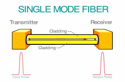
The glass portion of an optical fiber consists of two regions, the core that runs through the center of the strand, and the cladding that surrounds the core. While light rays want to go in a straight line, when they are aimed, or coupled, by a light source into a fiber, some of the photons will enter the core at widely divergent angles.
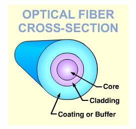
A fiber optic's cladding has a different refractive index than the core, reflecting the photons back into the core.
The cladding, which is said to have a different refractive index than the core, acts as a mirror. It causes the photons to reflect back into the core during their transmission through the system. Since the photons are traveling through the core at different angles, they will arrive at different times at the end of their journey. The result is an optical signal that is dispersed, that is, spread out over time. The wider the pulse spread, the less bits per second that can be transmitted on the system.
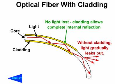
Without the cladding, the light pulses in the fiber optic cable would eventually dissipate.
Fiber optics solve two of the problems that had bedeviled early lightwave systems, including Mr. Bell's photophone. The light can be deflected around corners, thanks to the cladding, and it isn't affected by inclement weather.
The term 'lightwave' is a bit of a misnomer, since what we think of as light refers to that portion of the electromagnetic spectrum (EMS) that is visible to the naked eye -- 770 to 330 nanometers (770 X 10 meters to 330 X 10 meters).
However, optical fiber communication uses that portion of the spectrum which is least affected by attenuation and supports the longest cable spans -- the infrared (IR) regions at 850, 1350, 1400 and 1550 nm, which are invisible to the human eye. At these wavelengths, the transmission properties of available light sources are best matched with the transmission qualities of optical fiber.
But claiming that we communicate on 'beams of light' has a certain charm to it, so in general discussions we tend to take poetic license.
As mentioned, one challenge of fiber optics was reducing the dispersion of the photons as they traveled through the fiber. As shown in this multi-mode fiber, one source of dispersion is when photons from a light source enter the fiber at widely diverging angles. As such, many of the photons bounce from one side of the cladding to the next side, travelling a longer distance than the photons that travel directly down the middle of the core. These multiple paths, or modes, create a wider, or more dispersed output signal at the receiver, which makes them harder for the photodetector to detect.
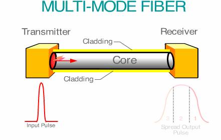
In a multi-mode fiber, the photons take different paths down the core, creating a spread pulse at the receiver.
To reduce this dispersion of the signal, Bell Labs researchers developed a graded index multi-mode fiber. This fiber has a specially developed core that permits the photons with wide angles of deflection to travel faster than the photons with little of no deflection in the core. This provides an output signal that is closer in shape to the input signal, which make them easier for the photodetector in the receiver to detect. This reduced dispersion means that means more bits per second that can be transmitted.
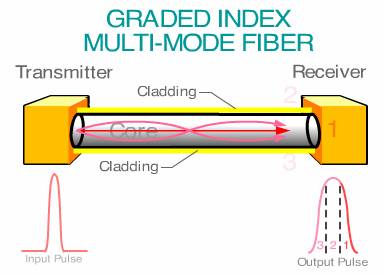
A graded index multi-mode fiber permits the photons near the cladding to travel faster than the photons in the center of the core, reducing pulse spreading at the receiver.
Another development is the single mode optical fiber, which has a very small diameter core, so small it permits only one path for the light rays to take down the center of the fiber. Pulse spreading is eliminated, permitting throughput in commercial fibers of 2.5 Gigabits/s to 40 Gb/s. This technology is used in high-throughput data and voice long distance transmission.
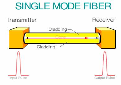
A single mode fiber forces the photons to travel down the center of the core, greatly reducing pulse spreading.
One of the challenges in lightwave transmission is reducing to an acceptable level the loss of power that photons experience while traveling through a fiber. Power can be lost due to a number of causes -- excessive bending of the fiber; poor connections and splices; differences in the refractive indexes of two media, such as when photons from a laser are coupled to the end of the optic core; and irregularities in manufacturing.
Another interesting problem is the absorption of light because of impurities in the glass. The figure below shows the loss of power (expressed in decibels) at various wavelengths, or 'windows' due to ionized water molecules (OH) in the glass. As you can see, the concentration of OH molecules in the 1400 nm region greatly affects power loss.
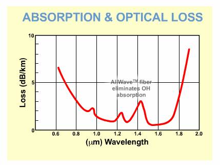
Bell Labs research has eliminated the ionized water molecules in the 1400 nanometer range, adding 100 nanometers, or 50 percent more usable wavelengths.
However, research at Bell Labs has reduced the OH molecules to such an extent that Lucent's AllWave(TM) fiber cable can harness the previously untapped 1400 nanometer region in the fiber spectrum to provide 100 nanometers, or 50 percent more usable wavelengths, than today's conventional fiber.
Because fiber cables can bend, they can be used in the same manner as copper cable, in homes, offices, factories. They can be buried in the ground, laid on the ocean floor, even strung from telephone poles.
And fiber doesn't care what type of signals it transmits: analog or digital; or the types of information: voice, data, video, graphics or fax.
And light traveling through fiber optic cables is very fast. In space or a vacuum, light travels at 299,800 kilometers per second, or 186,292 miles per second. Light travels slower in fiber -- about two thirds the speed of light -- but it still moves very fast.
Bell Labs researchers have recently developed a new L band amplifier for Lucent Technologies' WaveStar(TM) OLS 400GL dense wave division multiplexing (DWDM) system that increases the capacity and number of fiber types that can carry information.
Lucent's
UltraWave* family of optical fibers more than
doubles the capacity of transoceanic communications systems. The UltraWave
fiber, designed by Bell Labs researchers in
Lucent's lightwave systems, which combine TDM and FDM to expand the capacity of existing fiber systems, include:
Bell Labs also developed Lucent's WaveStar 40G Express, the first commercial system capable of delivering 40 Gb/s of capacity with a single laser over a single wavelength on a single fiber-optic cable. Lucent's 40 Gb/s TDM technology enables the WaveStar 40G Express to transmit the equivalent of about 500,000 simultaneous phone calls per second over a single wavelength.
Bell Labs also developed the industry's first all-optical digital access cross-connect system (DACS), a switch-like device which is used in central offices to connect 53-Mb/s-and-higher fiber transmission systems. In 1999, Lucent announced its WaveStar DACS 4/4/1 that uses a 'Bit-Slice Architecture' developed by Bell Labs to provide an initial 256 STM-1 equivalents and will support up to 1024 STM-1 equivalents.
|
Bell Labs researcher Fabio Pardo helped develop the WaveStar(tm) LambdaRouter, which uses a series of microscopic mirrors to instantly direct and route optical signals from fiber to fiber in a network. |
Bell Labs researchers have developed the first electrically powered organic laser, a breakthrough that may lead to more widespread use of lasers in various applications. The organic laser could be less expensive to manufacture than today's conventional inorganic semiconductor lasers.
And using FDM, a group of Bell Labs researchers has developed a laser that can transmit at 1,022 different frequencies. Called the 1,022-channel laser, this device carries information at the rate of 37 megabits (million bits) of information per second, for a total system capacity of more than 37 gigabits (billion bits) per second. The researchers believe the system can be scaled up to OC-48 data rates, for a capacity of several terabits (trillion bits) per second.
Lucent has also developed a high-bit-rate optical switch capable of directing 10 times the traffic of today's Internet in one second.
Based on Bell Labs' patent-pending MicroStar(TM) technology, Lucent's WaveStar(TM) LambdaRouter uses a series of microscopic mirrors to instantly direct and route optical signals from fiber to fiber in the network, without first converting them to electrical form as done today. This will save service providers up to 25 percent in operational costs and enable them to direct network traffic 16 times faster than electrical switches.
Bell Labs researchers also have demonstrated a record-breaking optical amplifier cable that carried 100 wavelengths (channels) of light.
And Bell Labs has transmitted a record 3.28 terabits (trillion bits) of information per second over 300 kilometers of an experimental Lucent TrueWave optical fiber. It also has demonstrated a record-breaking optical amplifier cable that carried 100 wavelengths (channels) of light.
Fiber optic cables are being used to connect switches between telephone company central offices, and in the private voice and data networks of large businesses. Fiber optics also are used to provide high-speed connectivity between computers in both public and private local and wide area networks (LANs and WANs), and they are used to connect servers in the Internet. They are also important in multimedia applications that rely on high bandwidth.
Fiber undersea cables also are girdling the Earth, linking nations together, and they also are found in such prosaic places as factories, power plants, and in other environments where copper facilities could be affected by electrical interference.
In entertainment, cable companies are replacing their copper coaxial cables with fiber optics to provide high-quality video signals to their customers and to provide other services as well.
Telecommunications companies also are looking at ways to bring fiber optic cables into every home in the loop plant, which will permit them to offer advanced Internet and other telecommunications services to their customers.
In some
countries, such as
And many companies are moving toward private high-speed data transport that use such worldwide protocols as fiber distributed data interface (FDDI), asynchronous transfer mode (ATM), and both synchronous optical networking (SONET) and synchronous digital hierarchy (SDH).
And Bell Labs recently developed a new protocol, included in Lucent's new WaveWrapper(TM) System, that reduces the bandwidth required for monitoring the network, in comparison to the bandwidth required for SONET/SDH.
Though invisible to us, each day we rely more and more on Mr. Bell's 'beams of light' so cleverly employed more than a century ago.
|
Politica de confidentialitate | Termeni si conditii de utilizare |

Vizualizari: 1737
Importanta: ![]()
Termeni si conditii de utilizare | Contact
© SCRIGROUP 2024 . All rights reserved