| CATEGORII DOCUMENTE |
| Arhitectura | Auto | Casa gradina | Constructii | Instalatii | Pomicultura | Silvicultura |
DOCUMENTE SIMILARE |
||
|
||
Design of RC Bars
Modules for Beams, Columns and Foundations - included in the hitherto available version of Robot - allow one to determine the required reinforcement area and the spacing of reinforcing bars within the cross-section of an concrete structure element.
The Members - required reinforcement (Design of concrete members) module allows one to calculate a theoretical (required) area of reinforcement for selected members. The option is accessible by selecting:
MEMBERS - REQUIRED REINFORCEMENT layout, included in the layout group titled DESIGN
the Analysis / Design of RC Structure Elements / RC Member Design / Calculations command from the menu.
The module is available for the following codes:
Eurocode 2
Eurocode 2 (French NAD)
Eurocode 2 (Belgian NAD)
Eurocode 2 (Dutch NAD)
Eurocode 2 (Italian NAD)
Eurocode 2 (German NAD)
Eurocode 2 (Finnish NAD)
American code ACI 318/95 and ACI 318/99 (metric)
Canadian code CSA A23.3-94
British code BS 8110.
French codes BAEL91 and BAEL 91 mod. 99
Dutch code NEN 6720
Spanish codes EH91, EHE98.
Russian code SNiP 2.03.01-84
Romanian code STAS 10107/0-90
Norwegian code NS 3473E
Singaporean code CP65.
MEMBER is the main calculation element in the Members - required reinforcement module. Usually it is a structure elelement of a certain type e.g. RC beam or RC column. Definition of a member type allows one to perform appropriate calculations of the theoretical (required) reinforcement according to the relevant code requirements. In some cases a member can be defined as a chain of successive members entered during the structure definition. The option used for definition of RC member type in a structure is available:
from the menu by selecting: Geometry/Code parameters/RC member type
from the toolbar,
by selecting the ![]() icon.
icon.
The process of member type definition in a structure is identical to the manner of defining other structure attributes. The type of an RC member is correlated with the relevant RC code that has been indicated as the basis for the design of structure bars. While working with the given code, one can edit and use only the members defined according to the code. The shape taken by the dialog box for defining RC member type is also correlated with the type of the member to be defined. The dialog box is different when one defines a member type belonging to the category of concrete beam, and its shape changes when one defines a member type belonging to the category of concrete column.
Before starting calculations of reinforcement area for members one should first determine calculation parameters. The option is available from:
from the menu by choosing Analysis / Design of RC Structure Elements / RC Member Design / Calculation Parameters command
on the DESIGN/ MEMBERS - REQUIRED REIFORCEMENT
layout, from a toolbar by pressing the ![]() icon.
icon.
The process of calculation parameter definition for structure members is identical to the manner of defining other structure attributes.
When the New set of calculation parameters icon is pressed in the Calculation parameters dialog box, a dialog box consisting of three tabs appears on the screen:
General
Longitudinal reinforcement
Transversal reinforcement.
In the above dialog box (as an example a dialog box for an ACI code is shown), parameters needed for RC element design that are not connected with its geometry such as: steel and concrete characteristics, used member types, covers, etc. are grouped. Remaining code parameters dependent on geometry are defined in the RC member type dialog box. The contents of particular tabs of the Calculation parameters definition dialog box are correlated with the selected RC code.
In the dialog box shown in the figure above, on the General tab two main fields are located: concrete parameters distinguished with a frame and additional parameters required in calculations. On the Longitudinal reinforcement tab, steel parameters, reinforcing bar types and cover to the edge or bottom reinforcement axis can be defined. On the Transversal reinforcement tab steel parameters for transversal reinforcement, reinforcement type and its parameters can be defined.
Starting theoretical (required) reinforcement calculation for RC member results in opening of the dialog box presented in the figure below.
When creating a structure model, the user defines geometrical parameters of concrete beams and columns (buckling parameters, allowable values of deflection and displacements at member ends). The code parameters of concrete structure elements (steel and concrete parameters, types of reinforcing bars) are defined in the Calculation parameters dialog box. The above dialog box contains the following options:
in the Calculation type field:
Design
Load capacity check (the option is currently not available).
in the Calculations for field, elements taken into account in calculations:
members
bar groups (the option is currently not available);
Lists of elements taken into account during calculations can be defined in three ways:
manually typing member numbers in an appropriate edit field
opening selection dialog box by means of '' button
indicating elements in the viewer containing a structure view
Design cases:
code combinations
case lists for each of the analyzed limit states;
A set of active fields differs depending on a selected code. The selection fields for code combinations are active only when such combinations were previously created and calculated. A case list may be entered in an appropriate edit field or in the Selection dialog box activated by means of '' button.
Number of calculation points for beams; it can be defined in two ways:
by determining a number of calculation points along a beam length (min. = 3, max.= 100)
by specifying every what length unit calculations are to be performed every; as a beginning point one adopts the point corresponding to the options accepted in the RC beam definition dialog box.
Results for calculations of theoretical (required) reinforcement area for RC members are available in table form; the results can also be presented in the form of diagrams along the bar length (see chapter 5.1).
Once the process of RC member design is completed the RC Member Calculations: Report dialog box, presented in the figure below, is displayed on the screen.
The above dialog box presents the following information:
list of designed RC members
list of members for which the calculations have been performed correctly
list of members for which warnings occurred during calculations
list of members for which an error occurred in calculations
additional notes.
The Calculations performed for bars field displays the numbers of RC members that underwent design; these must be the members such as RC beam or RC column, since these are the only elements for which a theoretical (required) area of reinforcement can be determined in RC members.
Next three fields available in the dialog box present short information concerning the run of RC member calculations. They divide the members into groups of members for which the calculations have been completed with the same result:
the first field Results of calculations for bars are correct displays numbers of members for which no warnings or errors occurred during design
the second field Results of calculations for bars contain warnings groups the members for which warnings occurred during RC member calculations. Note should be taken that in this dialog box a warning is treated in a more general way than in the result table for RC members. Thus, a warning may concern both exceeding the maximal reinforcement ratio (in the table it is presented in red color - code requirements are not fulfilled) and information that maximal allowable stirrup spacing has been applied (in the table, only the information in the Remarks column occurs).
the third field Results of calculations for bars contain errors groups the members for which errors occurred during RC member calculations; for these members the calculations have not been performed. In the result table such members are indicated by entering the word: error. Errors during calculations may result from:
Þ incorrect member definition; the following data may be inconsistent: section, member type and reinforcement parameters. All data should pertain to the same code and parameters describing an RC member. It is not allowed to assign sections to the member types that do not correspond to them; it also concerns sections of the same geometry
Þ code requirements that make calculations impossible (exceeding of allowable slenderness, maximal shear force or moment).
If errors or warnings occurred during RC member calculations, then in the lower part of the dialog box a message appears which informs a user how to obtain information regarding errors or warnings that have occurred.
If at least one of the designed elements has been a beam bent with respect to the Z axis or a beam bent biaxially, then in the lower part of the dialog box a message will appear informing how the results for such elements are presented in the result table.
In the bottom part of the dialog box the Reinforcement change button may be located. It is accessible only if calculations of RC member reinforcement have been performed according to a code which enables calculation of deflections and if at least one of the bars has not been verified due to deflection. Pressing this button opens the Change of reinforcement dialog box. The option enables semi-automatic correction of the calculated reinforcement in elements for which admissible deflection has been exceeded.
Presently, the program provides the possibility of deflection calculation (for the serviceability limit state) in the case of the following RC codes:
American RC codes ACI 318/99 and ACI 318/99 metric
British RC code BS 8110
Eurocode 2 (with different national application documents)
French RC codes BAEL 91 and BAEL 91 mod.99
Polish RC codes PN-84/B-03264 and PN-B-03264 (1999).
The top part of the dialog box contains a bar table; the following data is presented in individual table columns:
bar number
information if a bar has been verified or not
name of adopted reinforcement parameters
current bar deflection
admissible deflection
proportion - ratio of the current deflection value to the admissible deflection value.
The table enables selection (multiselection) of bars and sorting in columns.
In the middle part of the dialog box there are options grouped in the fields: Method of reinforcement change and List of load cases. The Method of reinforcement change field includes three options:
Proportional to required reinforcement area - the ratio of required reinforcement is increased by the calculated values in such a manner so that the proportions of top area and bottom area are preserved
Change of required reinforcement area - if in a given bar section the (top or bottom) required area is a non-zero value, then it is increased by the calculated value
Change of number of reinforcement bars - if in a given bar section the number of bars (at the top or bottom) is a non-zero value, then it is increased by the calculated number of reinforcing bars.
Depending on the option chosen, in the edit field provided under the above listed options, the user should specify:
dA= .. [%] - increment of the required area ratio
dA= .. [cm2] - area increment
dn - increment of bar number.
Values given in this edit field stand for increment of the appropriate quantity in relation to the values already existing. Pressing the Apply button causes recalculating and saving appropriate values for selected bars; if one bar has been chosen, then values available in the table provided in the bottom part of the dialog box are updated.
The List of load cases field presents the list of load cases (the field is inaccessible) that have been used during calculations of deflection for the serviceability limit state.
The bottom part of the dialog box contains a table with information concerning reinforcement area for a selected beam (if in the top table several bars have been chosen, the table in the bottom part of the dialog box is empty). Any value may be changed in the table. The table comprises the following data:
positions along the bar length
top and bottom required (theoretical) reinforcement
top and bottom number of bars
ratio of (required) reinforcement
rigidity
Note should be taken that:
if a new value of the required reinforcement ratio is specified, then new required (theoretical) areas of reinforcement and new number of bars are calculated
if a new value of required (theoretical) area of reinforcement is specified, then a new value of reinforcement ratio and bar number are calculated.
Calculations are carried out for areas resulting from a number of bars. After pressing the Verify button calculations for selected bars are performed. Once the calculations are completed, the program updates information in the table. If verification has proceeded correctly, the icon in the table is changed; the list of elements for which conditions have not been satisfied, is refreshed only on opening the dialog box, while working in the dialog box; only the results for the existing list are refreshed correspondingly.
To change reinforcement of RC members, the user should:
perform calculations of required (theoretical) reinforcement for RC members; once they are completed, the RC Member Calculations: Report dialog box is displayed on the screen
press the Reinforcement change button in the RC Member Calculations: Report dialog box; the Change of reinforcement dialog box opens then
select bar(s), choose the method of reinforcement change
press the Apply button
press the Verify button.
After calculations the user should check coefficients in the table presented in the top part of the dialog box. These operations should be performed as long as necessary to obtain an intended value of deflection for all the bars.
Theoretical (required) reinforcement of RC members obtained after calculations is interpreted in the following manner:
1. Longitudinal reinforcement
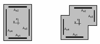
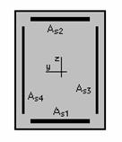
For biaxially bent columns with the rectangular, T-shaped, L-shaped or Z-shaped sections, the areas of reinforcement should be interpreted as follows:
As1= As2 = Reinforcement along b
As3= As4 = Reinforcement along h
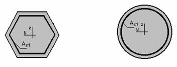
For columns whose cross section is described by: a regular polygon, circle, semicircle or circle quarter, the areas of reinforcement should be interpreted as follows:
As1 = Reinforcement along b - evenly distributed along the edge
For rectangular beams bent biaxially:
As1= Bottom reinforcement As2 = Top reinforcement
As1= Bottom reinforcement (Z axis) As2 = Top reinforcement (Z axis)
For elements with reinforcement in both planes, the results should be interpreted as follows:
The areas are treated independently - they have no common parts in the corners. The corner area of section reinforcement is assigned to the area resulting from bending in the Y plane.
2. Transversal reinforcement:
theoretical (required) stirrup spacing (Stirrup spacing) - spacing of the defined stirrups required for a given section
real (provided) stirrup distribution - the distribution which is assumed for a given section once the element has been divided into N equal parts (defined earlier in the Calculation Parameters dialog box) and once the distribution in each of the zones has been calculated
transversal reinforcement type/ distribution - presents the stirrup type and distribution in the number of zones defined earlier in the Calculation Parameters dialog box. The reinforcement type is described by the number of bars and their diameter linked by the letter f or a steel grade (according to the code). The designation 5f8 (4HA8, 4T8) denotes four-legged stirrups made from the bars of f8. The description of the distribution includes - for each zone - the number of stirrups and their spacing linked with multiplication sign, the zones are linked with the addition sign. The following description: 20*4.0+10*8.0+20*4.0 denotes three zones of stirrup distribution: the first one and the third one comprise 20 stirrups each spaced every 4.0 units of section dimension, the middle zone comprises 10 stirrups spaced every 8.0 units of section dimension. The valid units are the units according to which calculations were performed.
NOTE: In the result table a designing combination denotes such a combination for which, assuming the reinforcement calculated on the basis of all the combinations, the greatest section efficiency ratio is obtained. For thus-understood designing combination internal forces are presented.
A designing combination shows the most unfavorable set of forces for a given section, however, it may by no means be used in its design.
SELECTED REFERENCES (DESIGN OF RC STRUCTURES)
General Part
P.CHARON, Calcul des ouvrages en beton arme, Eyrolles, Paris 1986
V.DAVIDOVICI, Formulaire du beton arme, Le Moniteur, Paris 1996
J.EIBLE (ED.), Concrete Structures Euro-Design Handbook, Ernst & Sohn, Berlin 1994/96
J.G.MACGREGOR, Reinforced Concrete Mechanics and Design, Prentice Hall, New Jersey 1988
EC:
A.W. Beeby, R.S.Narayanan, Designers' Handbook to Eurocode 2 Part 1.1: Design of concrete structures, Thomas Telford, London 1995
BAEL:
J.PERCHAT, J. ROUX, Pratique du BAEL 91 Cours avec exercices corriges, Eyrolles, Paris 1998
H.THONIER, Conception et calcul des structures de batiment, Presses de l'ecole nationale des Pony et chaussees, Paris 1992
BAEL Regles techniques de conception et de calcul des ouvrages et constructions en beton arme, suivant la methode des etats limites, Eyrolles, Paris 1992
ACI:
Buiding Code Requirements for Structural Concrete (ACI 31-95) and Commentary (ACI 318R-95), ACI, Farmington Hills 1995
E.G.NAWY, Reinforced concrete: a fundamental approach, Prentice Hall, New Jersey 1996
S.K.GHOSH, D.FANELLA, B.RABBAT (ED.), Notes on ACI 318-95, Portland Cement Association, Illinois 1996
BS:
Structural Use of Concrete. BS 8110, BSI, London 1998
Handbook to British Standard BS 8110:1995. Structural Use of Concrete, Palladian Publications Ltd, London 1987
CH.E.REYNOLDS, J.STEEDMAN, Examples of the design of reinforced concrete buildings to BS8110, E & FN Spon, London 1992
W.MOSLEY, J.BUNGEY, Reinforced Concrete Design, McMillan Education Ltd, London 1987
F.KONG, R.EVANS, Reinforced and Prestressed Concrete, Van Nostrand Reinhold (UK), Berkshire 1987
EH/EHE:
Instruccion para el proyecto y la ejecucion de obras de hormigon en masa o armado EH-91, Ministerio de Fomento, 1998
Instruccion de hormigon estructural (EHE), Ministerio de Fomento 1999
R.FERRARAS, Manuel de hormigon armado, Colegio de ingenieros de caminos, canales y puertos, Madrid 1999.
|
Politica de confidentialitate | Termeni si conditii de utilizare |

Vizualizari: 2457
Importanta: ![]()
Termeni si conditii de utilizare | Contact
© SCRIGROUP 2025 . All rights reserved