| Username / Parola inexistente Login Register |
|
The digital controller can directly control two converters, which is performed by the monitoring S/W with real time. The monitoring S/W is coded by visual basic and C++ and used as a subroutine. Fig.1 shows a block diagram of proposed system. The charge system has two stages to supply low charging voltage. The charge voltage is directly converted AC 220V into 3.7V such that it can be unstable due to high current. Therefore, the AC Voltage is firstly stepped down 24V in the first stage and converted 3.7V through three paralleled forward converter at the second stage. Similarly, the discharging voltage is two low that cannot be directly delivered to return the AC power. Therefore the discharging system is also required power converters with the secondary stage. The proposed system is designed all possible to use during battery charging and discharging as a bi-direction rectification structure.
A. Design and analysisIn this paper, the charging system using the load current sharing is studied. The proposed battery charger as shown in Fig.3 is constituted of three forward converters that are connected in parallel and shared the load current. The sensed current from each converter is transmitted a control circuit and its current value is summed. And the total current is divided three signals and is performed as a control input to each converter. In charging, the PWM waveform of the SMPS for parallel operation is generated as shown in Fig. 2 The summation of each output waveforms with delta delay, which is based on the first SMPS, is similar to sine wave. The output signal is designed to be followed it even though the interval is changed. This method can be lessened the frequency distortion and the ripple than the driving method by only a converter.
Fig.2 PWM control waveform
The proposed converter has flexible characteristic for battery charging current with large capacity. Each module has independently self-closed loop, it is performed as the current mode until the constant charge status is reached. Then,
if the charge status is reached the required voltage, the charge current is
exponentially decreased by constant voltage method. In the equivalent model,
each modules are composed of capacitors, inductors, sensed current gain, The paralleled module system has the loop gain characteristic the same as single module because the identity power is supplied at load. Fig. 3 shows an equivalent model of the paralleled battery charger. If the load of converters is resistance load, the loop gain of the paralleled module system is expressed by
The open loop transfer function of a unit using state-space-averaging method is given by
From the equation (2) and (3), We know that the characteristic of forward
converter can be varied with by DC input voltage,
Fig.
3.Small-Signal Block Diagram of Parallel Module
The designed digital control circuit is performed periodically communication with the PC computer, driving/stop of system, charging/discharging selection, acquisition and transmission of voltage, current and temperature data during charging/discharging, emergency halt function due to system stop requirement etc. The communication with PC monitoring software is executed through the RS232C. The main selection related with system is carried out by an operation monitoring software, and the real time work for the test is acquired at a digital circuit. If a discharging voltage is reached at the blocking voltage, 2.7V, we can estimate what the discharging is completed. As the controller of discharging converter, TL494 is used, the starting and termination of discharging is controlled by TL494 driving power. The commutation of charging and discharging is performed by DC electromagnetic contactor, SMM-100P, the digital controller is induced by the TTL level. The input interface is used ADC board with 8-channel, the data is acquired with period per 300usec. The temperature sensing through PT100 component is possible by the precise measurement, the voltage value is changed with respect to resistance variation and calculated after compared conversion data table III. Batter control algorithmThe charging and discharging algorithm for a Li-polymer secondary battery is controlled by CC-CV mode in battery charging, and by the reference of the cut-off voltage in discharging. A control flow chart for battery charging shows in Fig. 4. If the battery voltage is reached a constant voltage, the active mode is commutated CC into CV in charging. That is, the charging start, the PWM output signal is maintained as the CC mode until the voltage of battery is reached at the rated value, 4.20.03V. And then, if this value is exceeded the rated voltage, the current value is neglected and the PWM output is controlled to keep a constant voltage. The limit value of the voltage, current and temperature data with 30usec cycle is always monitored and the charging is terminated in case of exceeding of limitation. When the control flowing in discharge mode compare with it in charging process, the discharge values are similar to the voltage, current and temperature in charging mode, but there is no need automatic switchover in the inner loop between charging and discharging mode. If the reference voltage, which is the cut-off voltage in the discharging, is reached to 2.7V, we can estimate as the discharging is completed. A flow chart of the battery discharging shows in Fig. 5. The charge controller generates a synchronize signal for the PWM which is needed for the parallel operation and a delay of each phase.
Fig. 4. Charging Control Flow chart Fig. 5 Discharging Control Flow chart
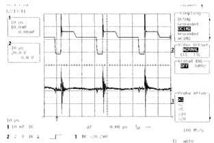
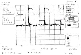
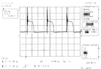
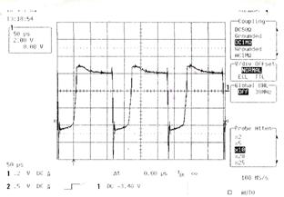
IV. Experimental resultsThe charging and discharging power system is composed of the power converter with a switching method, digital controller, monitor software and cell jig. The power converter in Fig. 1 is designed as the forward converter method with 200W capacity in charging, which is constitutes three converters in parallel and in charge of the CC/CV control of the battery cell. The total system can be lessened the size and heat dissipation because the power of the forward converter can be returned to the primary AC source in discharging test. The digital controller is charged of interface between operation S/W and power conversion and its output control. The charging and discharging mode performs the CC/CV mode and PIC16F877 is used as a main CPU for each module. Fig.6 shows a driving signal and its output current at 25A and 60A, respectively. From the Fig.6, the variable output current is shown that is controlled by the CC control. In Fig.6, the channel 1 is the current value with 20A/Div and the channel 2 is MOSFET voltage, Vds with 20V/Div. Fig.7 illustrates a driving waveform in the discharging converter. Fig 7(a) is Vds waveform of the main switch used in discharging, then the primary voltage of transformer is shown in Fig.7(b).
(a) In case of 25A load(PWM f= 30KHz, pulse width = 9.89usec)
(b) In case of 60A load (PWM f= 30KHz, pulse width = 12.75usec) Fig. 6. Charging Mode Result
(a) Vds waveform of MOSFET
(b) Voltage waveform of V1 Fig. 7. Discharging Mode result
V. ConclusionIn this paper, the battery charging and discharging system for the HEV, which is constituted three modules with 50A, is studied to perform a precision control of the Li-Polymer battery with low voltage and high current in charging. The characteristics of the paralleled converter is easily analyzed a modeling and the equivalent circuit analysis. The reliability of the proposed parallel converter is reviewed through the shared current of each module in charging mode. The status of the charger/discharger and battery are intensively monitored by developed the monitoring program, and stability, performance, reliability, and maintainability are carried out in the steady state and the step load variation. Each module is verified via the manufacturing of a prototype model and its charging and discharging experiment. The proposed prototype system should be developed as an algorithm to perform various charging/discharging test of the Li-Polymer battery in the future. Acknowledgment The authors wish to acknowledge their sincere thanks to Ministry of Commerce, Industry & Energy, Government of Korea for funding. References [1] Mark Jordan, 'UC3907 Load Share IC Simplifies Parallel Power Supply Design', Unitrode Application Note U-129, pp. 9-296~9-398. [2] Bob Mammano and Mark Jordan, 'Load Sharing with Paralleled Power Supplies,' Unitrode Switching Regulated Power Supply Design Seminar Manual, 1991, pp. 2-1~2-14. [3] F. Petruzziello, P. D. Ziogas, G. Joos, 'A Novel Approach to Paralleling of Power Converter Units with True Redundancy,' PESC 1990, pp. 808~813. [4] Chunxiao Sun, Brad Lehamn, Rosa Ciprian, 'Dynamic Modeling and Control in Average Current Mode Controlled PWM DC/DC Converters', IEEE PESC, 1999, pp. 1152~1157. [5] Shinuo Luo, Zhihong Ye, Ray Lee Lin, and Fred C. Lee,'A Classification and Evaluation of Paralleling Methods for Power Supply Modules', IEEE PESC, 1999, pp901~908. [6] Shinuo Luo, Zhihong Ye, Ray Lee Lin, and Fred C. Lee,'A Classification and Evaluation of Paralleling Methods for Power Supply Modules', IEEE PESC, 1999, pp901~908. [7] 'Hee-jun Kim,'Soft switching switch mode power supply',Proceeding of KIEE. Vol. 46. No 2, 1997, pp36~41 [8] Suh ,Ki-Young, Koo Heun-Hoi, Lee Hyun-Woo, 'Two transistor forward converter type low voltage high current DC power supply', kungnam Univ. RIET vol. 15, No1, 1997, pp103~114 Appendix
Fig. 8. Parallel
Fig. 9. Parallel
DISTRIBUIE DOCUMENTUL
© SCRIGROUP 2025. All rights reserved |
 Fig.
1. Configuration of Charging/discharging System
Fig.
1. Configuration of Charging/discharging System