| CATEGORII DOCUMENTE |
| Bulgara | Ceha slovaca | Croata | Engleza | Estona | Finlandeza | Franceza |
| Germana | Italiana | Letona | Lituaniana | Maghiara | Olandeza | Poloneza |
| Sarba | Slovena | Spaniola | Suedeza | Turca | Ucraineana |
Instrument Transformers
Instrument transformers are designed to facilitate the measurements of high currents and voltages in a power system with standard but very accurate low-range ammeters and voltmeters. They also provide the needed safety in making these measurements, as the primary and the secondary windings are electrically isolated. Instrument transformers are of two kinds current transformers and potential transformers.
The Current Transformer
The current transformer, as the name suggests, is designed to measure high current in a power system. The primary winding has few turns of heavy wire, whereas the secondary has many turns of very fine wire. In a clamp-on type current transformer, the current-carrying conductor itself acts as a one-turn primary. The wiring arrangements for a wound primary and clamp-on current transformers are shown in Figure 1.47. It is evident from the figure that a current transformer is merely a well-designed step-up transformer. As the voltage is stepped up, the current is stepped down.
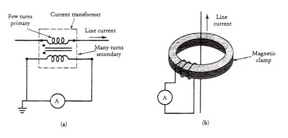
Figure 4.47 (a) Current transformer with wound primary. (b) Clamp-on type current transformer.
The low-range ammeter is connected across the secondary winding. Because the internal resistance of an ammeter is almost negligible compared with the winding resistance of the secondary, the ammeter can be treated as a short circuit. Therefore, the current transformers are always designed to operate under short-circuit conditions. The magnetizing current is almost negligible, and the flux density in the core is relatively low. Consequently, the core of a current transformer never saturates under normal operating conditions.
The secondary winding of a current transformer should never be left open. Otherwise, the current transformer may lose its calibration and yield inaccurate reading. The reason is that the primary winding is still carrying current, and no secondary current is present to counteract its mmf. The primary winding current acts like a magnetizing current and increases the flux in the core. The increased flux may saturate and magnetize the core. When the secondary is closed again, the hysteresis loop may not be symmetric around the origin but is displaced in the direction of residual flux in the core.
The increase in the flux causes an increase in the magnetizing current, which, in turn, invalidates its calibration. In addition, the primary current can produce excessive heat over a period of time and may destroy the insulation. Furthermore, the saturation may result in excessively high voltage across the secondary.
A current transformer is usually given a designation like 100:1. This simply means that if the ammeter measures 1 A, the current in the primary is 100 A. If an ammeter connected to a 100:5 transformer registers 2 A, the line current is 40 A.
The Potential Transformer
As the name suggests, a potential transformer is used to measure high potential difference (voltage) with a standard low-range voltmeter. A potential transformer, therefore, must be of the step-down type. The primary winding has many turns and is connected across the high-voltage line. The secondary winding has few turns and is connected to a voltmeter. The magnetic core of a potential transformer usually has a shell-type construction for better accuracy.
In order to provide adequate protection to the operator, one end of the secondary winding is usually grounded as illustrated in Figure 1.48.
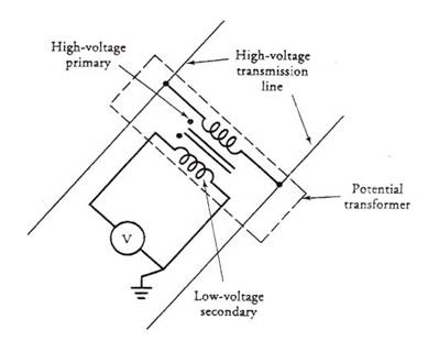
Figure 4.48 A potential transformer connected to measure high voltage with standard low-range voltmeter.
Since a voltmeter behaves more like an open circuit, the power rating of a potential transformer is low. Other than that, a potential transformer operates like any other constant-potential transformer. The a-ratio is simply the ratio of transformation. For example, if the voltmeter on a 100:1 potential transformer reads 120 V, the line voltage is 12,000 V. Some common ratios of transformation are 10:1, 20:1, 100:1, and 120:1.
The insulation between the two windings presents a major problem in the design of potential transformers. The primary winding may, in fact, be wound in layers. Each layer is then insulated in order to avoid insulation breakdown. Commonly used insulating materials in potential transformers are oil, oil-impregnated paper, sulfur hexafluoride, and epoxy resins.
|
Politica de confidentialitate | Termeni si conditii de utilizare |

Vizualizari: 2457
Importanta: ![]()
Termeni si conditii de utilizare | Contact
© SCRIGROUP 2025 . All rights reserved