| CATEGORII DOCUMENTE |
| Arhitectura | Auto | Casa gradina | Constructii | Instalatii | Pomicultura | Silvicultura |
DOCUMENTE SIMILARE |
|||
|
|||
Design of RC Structure Elements
The purpose of the following modules: R/C beam design, R/C column design, Foundation design, Continuous footing design and Deep-beam design is to define, calculate and design concrete beams and columns in a structure (the module allowing R/C plate design is described in chapter 6.6). The current version of the program allows design of structural elements according to:
American codes ACI 318/99 and ACI 318/99 (metric) - beams, columns, spread footings
British code BS 8110 - beams, columns, spread footings
Eurocode 2 (Belgian NAD, Italian NAD) - beams, columns
French RC codes B.A.E.L. 91 and B.A.E.L. 91 mod.99
Spanish code EHE 98 - columns
Russian code SNiP 2.03.01-84 - columns, spread footings
Singaporean code CP65 - available modules as for BS.
The modules mentioned above can be used in two ways. They can be treated as an integral part of the Robot Millennium system (with a link to other modules which are responsible for structure definition and data transfer) or as an independent module (i.e. stand-alone) for R/C structure element design only.
During structure design the user can easily enter, display and change the structure and design parameters. If the obtained results do not meet the users' criteria, calculations can be repeated for different values of design parameters or for different cross sections.
The following chapters explain how to deal with modules for R/C design and address both approaches.
If modules for R/C structure design are used as a part of Robot program, then having calculated the forces operating within a structure and having shifted to the stage of designing particular structure elements, a dialog box shown in the figure below appears on the screen (this is the dialog box for R/C beams). The shape of the dialog box depends on the module that has been activated (R/C beams or R/C columns.
In case of R/C beams it is possible to get to the R/C beam design module after selecting a beam or a group of co-linear spans by calling the Analysis / R/C beam design command from the main menu.
Then the program transfers the relevant loads to the beam automatically. The loads are displayed in the Loads dialog box.
After entering the beam design module, there appears a dialog box allowing one to determine the type of loads to be transferred: Simple cases or Manual combinations. In case of the Polish code, there appears an additional field that allows one to define the participation of variable long-term loads, required for the calculation of deflection. If one selects the Simple cases option, the programs transfers the loads for which the program internally creates code combinations according to the regulations prepared for R/C structures, available in the CFG folder in the file with *.rgl extension.
If one selects the Manual combination option, calculations are performed for the combinations defined in the Robot program. Apart from that, there appears the list of all manual combinations and the user may select them.
The Grouping type field contains options that allow automatic grouping of elements according to certain criteria:
according to story - once this option is selected, the program - based on the structure geometry - divides the structure into stories and on their basis creates levels in the calculation tree in the beam and column modules ascribing automatically elements to the relevant level
according to geometry (in the current version the option is available only for columns) - once this option is selected, elements of the same geometry are treated as one calculation element; afterwards, it is designed for many combination groups resulting from loads acting on individual elements - in consequence, all the elements are designed for the most unfavorable arrangement of loads.
The bottom part of the dialog box contains the Supports of the grillage beam button. Pressing the button results in opening the dialog box. The option is used to determine which of the adjoining elements are to be treated as supports for the indicated beam. The settings have direct bearing on the type and shape of reinforcement in the beam in question.
The Supports of the grillage beam button is active when there are other beam-type elements adjoining the beam in question. The bottom part of the dialog box displays a table containing a list of adjoining elements (bar number accompanied by a section label).
Supports in the form of columns are identified automatically and there is no possibility of switching it off.
In case of R/C columns, it is possible to get to the column design module taking account of loads in column nodes after selecting a beam or a group of columns and by calling the Analysis / Design of RC Structure Elements / RC Column design command from the main menu.
Then the program transfers the nodal loads to the column automatically. The loads are displayed in the Loads dialog box.
After entering the column design module, there appears a dialog box allowing one to determine the type of loads to be transferred: Simple cases or Manual combinations.
Apart from the load values and natures, the Group field is filled up in the table of loads. It contains the number of the bar from which a load is transferred
If a group of columns is to be designed together (which means that calculation result in one column type for all the columns of the group), one should carry out group selection of the columns and call the R/C column design option. Then, the dialog box for loads displays as many load groups as there are selected columns. After calculations one obtains for each load group a "resultant" column, capable of resisting the load belonging to each group. Identical column geometry (section and height) and identical column support conditions are the requirements to be met for the group to be calculated.
The modules used for design of RC structure elements also provide access to the reinforcement calculator (the option is activated by selecting the following option from the menu: Structure/Reinforcement/Reinforcement Calculator
The bar diameters and reinforcement areas are given in the units chosen in the Preferences. The Calculator allows calculation of the following values (d denotes the reinforcing bar diameter):
reinforcement area:
(for example:
7*d 12 = 7.92 cm2
7*d 12 + 5* d 16 = 17.97 cm2
7*d 12 + 5*d 16 + 8*d 10 = 24.25 cm2
the required number of reinforcing bars (for example 44/d14 = 29 bars)
the required number of reinforcing bars of a predetermined diameter (e.g. 18 and 12 mm) with an additional condition given that the number of bars of both diameters is approximately equal (for example: 44 /d 18 /d 12 = 12*d 18.0 + 12*d 12.0)
the required number of reinforcing bars of a given diameter (e.g. 18 and 12 mm), so that the bars with the diameter of 12 mm make up a predetermined percentage of all bars (e.g.: 44 /d 18 /d 12 %25 = 16 * d 18.0 + 5 * d 12.0)
the difference between the given area (i.e. 44 cm2) and the sum of the given reinforcing bar areas (e.g.: 44 - 5* d 12 = 38.35 cm2).
RC Beam Design
The R/C beam design module allows for definition, calculation and design of continuous beams (both single and multi-span). Load cases may consist of vertical concentrated forces, uniform loads or additional support moments. Rectangular and T-sections are admissible (in addition, various beam slab connection types are taken into account).
The R/C beam design module can be called up in the following way:
select the R/C beam design from the structure type vignette (see chapter 2.1) - the module will work as an independent program (stand-alone) with no link and data transfer with other Robot Millennium parts
once the structure is defined, select (by highlighting in the graphic viewer) the appropriate list of bars creating the beam and choose the R/C beam design command from the menu. The BEAM layout will be opened and geometry and member loads along with corresponding results will be loaded into the code module. The screen will be divided into two parts: the viewer displaying the designed beam and the viewer for the presentation of the entire structure.
The description of the R/C beam design process presented below applies to the second method of calling the R/C beam design module; the main differences between the two approaches will be pointed out.
Once the module is chosen, the selected beam structure will appear in the upper part of the screen. Its geometry, applied loading and static analysis results will be loaded to the R/C beam design module (whereas in the case of the module working independently the user must define the geometry and loading and run static analysis). The beam geometry and loads can be modified by using the following options:
beam
section geometry - available by selecting the Geometry/Section Type command from the menu or pressing the Section
Type icon: ![]()
elevation
dimensions of the beam span - available by selecting the Geometry/Dimensions command from the menu or pressing the Dimensions
icon: ![]()
loads -
available by selecting the Geometry/Loads command
from the menu or pressing the Loads icon: ![]()
|
Section geometry can be defined/modified in the dialog box presented below. To modify the span(s) select the ones, whose section dimensions are to be changed. Selected spans will be highlighted. Rectangular, I-sections and T-sections are admissible (in addition, various beam-slab connection types are taken into account). Dialog box contents (parameters) vary according to the selected type. The dialog box beside contains only the General Parameters tab for rectangular sections. Similar parameters are available for the T-section and I-section types. Once the T-section with lower-positioned flanges is selected, the dialog box will contain two additional tabs: Slabs (enables defining dimensions of the floor slab: concreted on site or prefabricated) and Cuts (enables defining dimensions of cuts in the right or left part of the cross section). |
|
The program assigns automatically names to sections of RC beams/columns. The first letter B or C corresponds to beam or column, while the following one determines the shape of the section. It is followed by the characteristic dimensions. For instance, BR 30x50 denotes a rectangular beam section, for which b=30 and h=50.
Elevation dimensions for consecutive beam spans can be modified in the Elevation Definition dialog box. As in the case of cross section dimensions, the dimension definition/modification applies only to the selected span.
Once the Load option is selected the LOAD layout of the Robot Millennium system (in the case of a version integrated with other modules) or appropriate tables to define the loads (in case of the module working as a stand-alone programs). The selection of the Loads option allows the definition of loads applied to an R/C beam. This is done by:
left-clicking
on the "Load Definition" icon ![]() or,
or,
selecting the Structure / Loads command from the menu
choosing BEAM - LOADS
The dialog box shown below will appear on the screen.
To define R/C beam loads:
In Spans, enter the number of spans to which the load will be applied; if one writes A (all) in this field, all the spans will be selected,
From the Nature list, select the load nature (dead, live, snow, wind, etc.),
From the Load Category list, select the type of the applied load (continuous, concentrated, and surface).
Define the values of the selected load type (the icons in the upper part of the dialog box present schematically available load types) and press the Add button.
The left side of the load dialog box depends on the load type selected. The schematic icon representing the selected continuous or concentrated load type is displayed in the upper left corner of the dialog box. Icons allowing the selection of the load type are located on the right side. In the case of a planar load, the Coordinates field contains the following options: alpha, beta and y; the adjacent area contains the field allowing one to define the value of p load (load per unit of area). This load is transformed into a distributed load. The following planar load types are available: loads gathered from the plate surface between two beams. One should define the distance y from which the loads are gathered and two types of loads gathered from the plate surface is delimited by four beams.
Below the Load Type
icons, is the Relative Dimensions
field and, in the case of having selected a continuous load type, the Dimension Chain option. If the Relative Dimensions option is active -
the symbol ![]() appears, then during the load position
definition, the relative point coordinates will be used from the interval
<0,1> will be used. If the option is not active then the point coordinates
will be given in the units selected by the user. In the case of the continuous
load - the Dimension Chain option (if
this option is active - the symbol
appears, then during the load position
definition, the relative point coordinates will be used from the interval
<0,1> will be used. If the option is not active then the point coordinates
will be given in the units selected by the user. In the case of the continuous
load - the Dimension Chain option (if
this option is active - the symbol ![]() appears) is
available. During continuous load definition the so-called dimension chain will
be used. This means that the continuous load values p2 will be applied at a
point with the coordinate (x1+x2) load value p3 at a point with the coordinate
(x1+x2+x3) etc. If the option is inactive, then the load p1 is applied at a
point with the coordinate x1, load p2 at a point with the coordinate x2 etc.
appears) is
available. During continuous load definition the so-called dimension chain will
be used. This means that the continuous load values p2 will be applied at a
point with the coordinate (x1+x2) load value p3 at a point with the coordinate
(x1+x2+x3) etc. If the option is inactive, then the load p1 is applied at a
point with the coordinate x1, load p2 at a point with the coordinate x2 etc.
The fields Co-ordinates and Value fields are located in the middle portion of the dialog box. In the case of a concentrated load, two other options, x1 and F or M are located here.
In the case of a continuous load, the Co-ordinates field contains the options: x1, x2, x3, x4.
The Value field contains the options: p1, p2, p3.
NOTE: When a continuous load is selected, not all the fields allowing co-ordinate load value definition are active.
For each beam the following parameters can be defined:
openings
(by selecting the Geometry/Openings
command from the menu or pressing the icon: ![]() ) - a dialog box for definition of openings for
a selected beam span will be displayed.
) - a dialog box for definition of openings for
a selected beam span will be displayed.
story
parameters (story level, fire resistance, cracking and exposure rating) - by
selecting the Analysis/Story Parameters
command or pressing the icon ![]() - the
options included in this dialog box depend on the selected code of RC structure
element design
- the
options included in this dialog box depend on the selected code of RC structure
element design
calculation
options (by selecting the Analysis/Calculation
Options command or pressing the icon ![]() ) - the options included in this dialog box
depend on the selected code of RC structure element design
) - the options included in this dialog box
depend on the selected code of RC structure element design
reinforcement
parameters (by selecting the Analysis/Reinforcement
Parameters command
or pressing the icon ![]() ) - the options included in this dialog box
depend on the selected code of RC structure element design.
) - the options included in this dialog box
depend on the selected code of RC structure element design.
NOTE: Once
any changes are made to the beam geometry or its loads, analysis results become
unavailable. To obtain appropriate results for the modified beam, the structure
needs to be updated (so the changes can be saved). This is possible by
selecting the Results/Structure Updating command or pressing the icon ![]() . Once the
geometry is updated, the entire structure has to be re-calculated.
. Once the
geometry is updated, the entire structure has to be re-calculated.
Beam calculations
and design can be started once all parameters have been assigned. It can be
carried out by either selecting Analysis/Calculations option or pressing the icon ![]() . Internal force
envelopes (moments and shear forces) and displacements are calculated for the
defined loads.
. Internal force
envelopes (moments and shear forces) and displacements are calculated for the
defined loads.
To view design results the following Robot Millennium system layout needs to be called up:
BEAMS - RESULTS
BEAMS - REINFORCEMENT
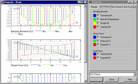
Once the BEAMS - RESULTS layout is selected, the screen will be divided into two parts: the left part containing the Diagrams field for graphic presentation of results and the right one containing the Diagrams dialog box. This dialog box allows you to display results in a tabulated format and select values for which diagrams in the left part of the dialog box will be presented (the options included in the Diagrams dialog box depend on the selected code of RC structure element design). Among those values section forces for available limit states, reinforcement areas and deformations can be found.
|
Sample diagrams for the multi-span beam are presented in the figure. |
|
Once the BEAMS - REINFORCEMENT layout is selected, the screen will be divided into four parts: a field in which beam elevation along with calculated reinforcement is presented, a field containing reinforcement in the beam section, a summary table with description of consecutive reinforcement rods and the Reinforcing bars dialog box presenting parameters of selected bars.
The program provides also several options allowing one to edit the reinforcing bars to be used in an RC beam:
starter bars - the option allows the user to determine the parameters of the reinforcing bars that connect a beam to a column. The option is accessible by selecting the Structure / Reinforcement / Starter bars command in the main menu or the Starter bars command from the context menu
division of reinforcing bars - the option allows the user to define the points of division of RC beams. It is accessible by selecting the Structure / Reinforcement / Divide reinforcing bars command from the menu. There is also the Connect reinforcing bars option available
parameters (properties) of reinforcing bars - the option is used to present the parameters of reinforcing bars, determined during RC beam design.
The following options are also available for all RC structure element design modules:
Visibility - it is used to select reinforcing bars to be presented in the graphical
viewer in the calculated RC structure elements (command: Structure / Reinforcement / Visibility or icon ![]() ).
).
One may chose to present the four main types of RC structure element
reinforcement: main reinforcement, transversal reinforcement, structural
reinforcement and reinforcement of openings (only for beams and deep beams).
Translation - it is used to perform the operation of translation on the formerly selected reinforcing bars in RC structure elements (command: Structure / Reinforcement / Translation).
Stirrup spacing - it is used for manual modification of the stirrup spacing in a beam (the Structure / Reinforcement / Stirrup Spacing command).
NOTE: The option is available in the menu only after stirrups are selected in a calculated RC beam.
After completing calculations, the results can be presented in the form of calculation notes (Results/Calculation Note option). The Robot Millennium system text editor containing data on the designed beam and calculation/design results will be displayed on the screen.
Once the Results/Drawings option is selected or
the icon ![]() is pressed, the Robot program will
activate the FINAL DRAWING layout
presenting a working drawing for the calculated and designed beam. The selected
beam span(s) will be presented on the drawing. The working drawing of a beam
will be presented on screen in the form which corresponds to the adopted
drawing parameters (see chapter 5).
is pressed, the Robot program will
activate the FINAL DRAWING layout
presenting a working drawing for the calculated and designed beam. The selected
beam span(s) will be presented on the drawing. The working drawing of a beam
will be presented on screen in the form which corresponds to the adopted
drawing parameters (see chapter 5).
2 Definition of RC Beams - Interactive Mode
At present, the RC Beam Design module offers an interactive mode of beam definition; the hitherto-available mode of RC beam definition and calculations requires activation of several dialog boxes in which beam / reinforcement parameters have to be determined. The interactive mode of RC beam definition enables defining geometry, story parameters, calculation options and reinforcement pattern for beams in a few dialog boxes following one another (without the need of extensive knowledge on the options provided in the module).
In the course of beam definition, the user determines parameters in the dialog boxes; a part of these dialog boxes is identical as those used in the hitherto-available mode of beam definition (it makes edition of the entered values easier)
To start the interactive mode of RC beam definition, the user should choose the command File / Beam Wizard from the menu in the RC Beam Design module. The dialog box shown in the picture below appears on the screen then.
In the above dialog box one of the following options may be chosen:
Create new - if this option is selected, then a beam with default parameter settings will be defined; the parameters may be modified while defining a beam in the Beam wizard dialog box
Create new based on the current beam - if this option is selected, then a beam with parameters adopted from the beam currently presented, will be defined; switching on the Retain loads option causes loads specified for the selected beam to be taken over by the defined beam; the defined beam may be saved under a new name
Modify current - selection of this option allows modification of an existing beam; a modified beam may be saved under the same name or a new one.
After pressing the Next > button the dialog box presented below appears.
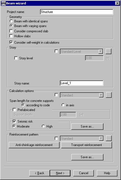
In the top part of the dialog box basic information about the defined RC beam and the RC beam geometry should be given; the RC beam definition (options available in the successive dialog boxes) depends on a type of RC beam:
Project name
Beam with varying spans (dimensions of RC beam spans are defined for each span separately)
Beam with identical spans (identical span geometry: cross section dimensions and type as well as span length, is defined for all RC beam spans).
Further on the following options are provided:
Consider compressed slab - if this option is switched on, then cooperation of a rectangular section with a compressed slab will be considered in the section definition
Optimization of flanges - if this option is switched on, then the overhang of flanges in the RC beam section is chosen in such a way so that it is not necessary to take account of splice reinforcement for beam and slab
Hollow slabs - if this option is switched on, then the cuts ensuring the support for prefabricated slabs on a beam, will be considered in a section definition; by default, such a section will be adopted for all the spans in a beam, however, it is possible to modify it for a selected span
Consider self-weight in calculations - if this option is switched on, then self-weight will be automatically added to the load cases.
Below the following parameters may be determined:
story parameters in the Story field; story parameters may be defined in two ways:
by activating the option and selecting - on the selection list - an earlier-defined file containing story parameters, e.g. a file named standard - pressing the () button opens the Story Parameters dialog box for a selected RC code; all the remaining options in the Story field are not accessible then
if the option enabling selection of a file from the selection list with files containing story parameters is switched off, then the remaining options in the Story field become accessible; if such a setting is chosen, then parameters defined in this field will be considered in calculations
parameters of calculation options for RC beams in the Calculation options field; calculation options may be defined in two ways:
by activating the option and selecting - on the selection list - an earlier-defined file containing calculation option parameters, e.g. a file named standard - pressing the () button opens the Calculation Options dialog box for a selected RC code; all the remaining options in the Calculation options field are not accessible then
if the option enabling selection of a file from the selection list with files containing calculation option parameters is switched off, then the remaining options in the Calculation options field become accessible; if such a setting is chosen, then parameters defined in this field will be considered in calculations; pressing the Save as button enables saving to a file the following parameters: span length, prefabrication and seismic dispositions
parameters in the Reinforcement pattern field; reinforcement parameters may be defined in two ways:
by activating the option and selecting - on the selection list - an earlier-defined file containing reinforcement parameters, e.g. a file named standard - pressing the () button opens the Reinforcement Pattern dialog box for a selected RC code; all the remaining options in the Reinforcement pattern field are not accessible then
if the option enabling selection of a file from the selection list with files containing reinforcement parameters is switched off, then the remaining options in the Reinforcement pattern field become accessible; if such a setting is chosen, then parameters defined in this field will be considered in calculations; pressing the Save as button enables saving to a file the following parameters: anti-shrinkage reinforcement (pressing this button opens an additional dialog box), transport reinforcement (pressing this button opens an additional dialog box), consideration of breaks in concreting.
Defined values of the parameters are confirmed by pressing the Next > button in the dialog box (the program proceeds to the next dialog box); there is also a possibility to return to the previous dialog box by pressing the Back <button.
Once the RC beam geometry is defined, the user should define loads acting on the beam and next, run calculations of the RC beam reinforcement.
3 RC Column Design
The R/C column design module allows you to calculate, pre-dimension and verify R/C columns. Axial forces and moments in both directions are admissible. The following cross section types are available: regular (rectangular, round or regular polygon) and irregular (T-section, Z-section, semicircle etc.).
The R/C column design module can be called up as follows:
select the R/C column design from the structure type vignette (see chapter 2.1) - the module will work as an independent program (stand-alone) with no link and data transfer with other modules. The Robot Millennium system is responsible for the structure definition.
once the structure is defined, select (by highlighting in the graphic viewer) the appropriate list of bars creating the column and choose the R/C column design command from the menu. The COLUMNS layout will be open and geometry and member loads along with corresponding results will be loaded to the code module. The screen will be divided into two parts: the viewer with the designed column elevation display and the viewer with the column section display.
The description of the R/C column design process (presented below) applies to the situation when the module works as a stand-alone program.
The screen will be divided into two parts: a viewer containing the column elevation display and the viewer with the column section.
Column definition is based on the following data:
column
elevation dimensions - available by selecting the Structure / Dimensions command or pressing the icon ![]()
type and
dimensions of the column cross section - available by selecting the Structure / Section Type command or
pressing the icon ![]() , after which the dialog box presented below
will be displayed on the screen. The section type (rectangular, round,
T-section, Z-section, L-section, regular polygon, semicircle or quadrant)
should be specified and dimensions of the selected section type are to be
entered (they will be displayed on the schematic drawing in the upper right
corner of the dialog box).
, after which the dialog box presented below
will be displayed on the screen. The section type (rectangular, round,
T-section, Z-section, L-section, regular polygon, semicircle or quadrant)
should be specified and dimensions of the selected section type are to be
entered (they will be displayed on the schematic drawing in the upper right
corner of the dialog box).
The program assigns automatically names to sections of RC beams/columns. The first letter B or C corresponds to beam or column, while the following one determines the shape of the section. It is followed by the characteristic dimensions. For instance, CR 30x50 denotes a rectangular column section, for which b=30 and h=50.
|
column
buckling model - available by selecting the Structure/Buckling Length command or pressing the icon |
|
Buckling models presented in the above dialog box depend on a selected RC code. They are based on the following code recommendations:
ACI 318 - nomograms in the notes concerning the point (in ACI 318-95 points 10.12; 10.13)
BAEL - since there are no code guidelines, they are based on nomograms included in EC2 in the point Slenderness of Isolated Columns (in ENV 1992-1-1 (1991) point 4.3.5.3.5 figure 4.27 formula 4.60)
BS 8110 - point 3.8.1.6
Eurocode 2 Belgian NAD - based on nomograms included in EC2 in the point Slenderness of Isolated Columns (in ENV 1992-1-1 (1991) point 4.3.5.3.5 figure 4.27 formula 4.60),
PN-B-03264 - Annex C.
Values ascribed to the models are the simplified representation of typical cases.
In the last three options code formulas and nomograms are directly applied.
After double-clicking on the icons shown in the drawing above, the program opens the dialog box where node rigidity may be defined.
applied
loads - available by selecting the Structure/Loads command
or pressing the icon![]() , after which a dialog box containing a table
for column load definition will be displayed on the screen. The following data
is included: case name, nature, group, axial force value, shear force value and
bending moments applied to the column.
, after which a dialog box containing a table
for column load definition will be displayed on the screen. The following data
is included: case name, nature, group, axial force value, shear force value and
bending moments applied to the column.
Moreover, there is a possibility to add automatically the loads coming from the upper column and beam (a column may be positioned with respect to a beam; names of beam supports are selected and columns are associated with a beam support - successive records being the reactions of successive simple cases are entered to the dialog box for loads).
As in the case of R/C beams, the following parameters can be defined:
story
parameters (story level, fire rating, cracking and exposure rating), by
selecting the Analysis/Story Parameters
command or pressing the icon ![]() - the
options included in this dialog box depend on the selected code of RC structure
element design
- the
options included in this dialog box depend on the selected code of RC structure
element design
calculation
options (by selecting the Analysis/Calculation
Options command or pressing the icon ![]() ) - the options included in this dialog box
depend on the selected code of RC structure element design
) - the options included in this dialog box
depend on the selected code of RC structure element design
reinforcement
parameters (by selecting the Analysis/Reinforcement
Parameters or
pressing the icon ![]() ) - the options included in this dialog box
depend on the selected code of RC structure element design.
) - the options included in this dialog box
depend on the selected code of RC structure element design.
|
Column
calculations and design can be started after defining all parameters. It can
be done either by selecting the Analysis/Calculations or pressing the icon |
|
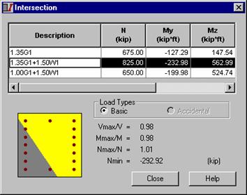
The upper part of the dialog box contains a list of all load combinations taken into account during column design process. For a selected combination the following values are displayed: column section with neutral axis, compression and tension area and corresponding safety factors. After calculations, the worst load combination (design combination) is presented in the dialog box.
NOTE: If the above dialog box contains identical combinations with different values of internal forces calculated for these combinations, it means that the values of internal forces have been calculated for different sections along the column length.
To view design results the following Robot Millennium system layouts are to be called up:
COLUMNS - RESULTS
COLUMNS - REINFORCEMENT
Once the COLUMNS - RESULTS layout is selected, the screen will be divided into two parts (see the drawing below).
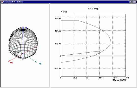
This dialog box contains N-M interaction curves for a given load combination. The left part of this box is used to display the 3D N-Mx-My interaction surface, whereas the right one is for the N-M interaction curve. The latter is the intersection of the 3D-interaction surface and the N-M plane containing currently analyzed load combinations.
Once the COLUMNS - REINFORCEMENT layout is selected the screen will be divided into four parts: a field containing the column elevation display along with calculated reinforcement, a field with reinforcement in the column cross section, a summary table with description of consecutive reinforcement rods and the Reinforcing bars dialog box.
As in the case of RC beams, the program provides also the Parameters of reinforcing bars option used to present the parameters of reinforcing bars, determined during RC column design.
Additionally, apart from the Visibility and Translation options (which have been discussed with reference to R/C beams), the column design module contains the Stirrups arrangement and Dowel Bars options. The option is used for manual definition of the shape of transversal reinforcement of a column or dowel bars (at the level of a column cross-section). The options are applied after calculations of column reinforcement are performed.
After completing calculations, the results can be presented in the form of calculation notes (Results/Calculation Note option). The Robot Millennium system text editor containing data on the designed column and calculation/design results will be displayed on the screen.
Once the Results/Drawings option is selected or
the icon ![]() is pressed, the Robot program will
activate the FINAL DRAWING layout
presenting a working drawing for the calculated and designed column. The
working drawing of a column will be presented on screen in the form which
corresponds to the adopted drawing parameters (see chapter 5).
is pressed, the Robot program will
activate the FINAL DRAWING layout
presenting a working drawing for the calculated and designed column. The
working drawing of a column will be presented on screen in the form which
corresponds to the adopted drawing parameters (see chapter 5).
4 Foundation Design
The Foundation design option allows the user to define, analyze, and design rectangular spread footings as well as continuous footings (to be placed under concrete wall). Footings can be either concentrically or eccentrically loaded. The footing stability and soil bearing stress distribution are also checked.
The main features of the foundation design option are:
customization of units, display formats, and material properties,
possibility of defining soil parameters and footing geometry,
interactive input of footing parameters,
possibility of defining constraints e.g. position of a pier on the footing or footing and/or pier thickness,
possibility of defining as many load cases as required.
The foundation design includes:
automatic footing dimensioning,
verification of sliding,
verification of overturning and minimum bearing (contact) area of footing surface,
verification of footing thickness,
dimensioning according to entered shape proportions or dimensions,
accounting for ground water level,
on-line visualization of results,
evaluation and detailing of footing and pier reinforcing,
summary of earthwork, concrete, formwork, and reinforcing quantities.
The foundation design module is divided into following system layout:
definition (of geometry and type)
load
soil
results
reinforcement.
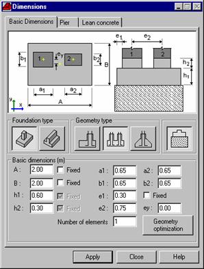
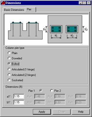
During the definition, the type and the basic dimensions of the footing and pier are defined. The user can choose between the spread footing and continuous footing to be placed under a concrete wall, as well as spread or continuous footing on lean concrete. One may also specify foundation geometry (rectangular spread or continuous footing, rectangular spread or continuous footing to be placed under two columns, spread or continuous footing of a tapered section). There is an option to specify the constraints/limitation according to which the design would be performed (geometry optimization). The following limits are currently allowed: all the geometric dimensions, shape of the plan of footing, type of eccentricity, offset of the column, and the adjacent footing condition. The definition also includes the type of the connection between the column/wall and the footing (see the dialog boxes below). In the case of selecting a foundation on lean concrete, the below-presented dialog box presents additional tab (Lean concrete) that allows one to define the geometry of lean concrete.
|
|
|
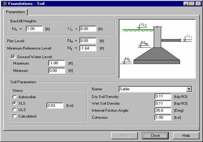
Together with the program, the soil database is provided; it enables direct application of correlational relationships described in the appropriate code. Once the basic soil characteristics are defined, the remaining parameters are calculated automatically in the table. Basic soil parameters may be changed; fields in the soil table, except for the fields containing basic parameters, are inaccessible.
The load system layout consists of the following windows: dialog box (to enter/modify the load on the footing, see picture), graphical window (with the picture of the current footing), tables (to enter/modify the current load), and schematic for the footing location.
|
In the dialog box beside, one can define the loads applied to a foundation. The list of the available load categories contains two items: the foundation load described above and the backfill load. Several load natures are available: dead, live, snow, wind, and seismic. Three load types are available: axial load, load with a normal force, a bending moment and a shear force, load with a normal force, a bending moment and a shear force acting in two directions. Depending on the load selected, appropriate edit fields allowing to define the force values will appear. |
|
The direction, type of load (dead, live, wind, snow, seismic), and category (foundation, backfill) can be specified. The load factors are determined on the basis of the type of the load.
In the soil module user can specify the soil conditions: all the necessary levels (with regard to the reference level), for example ground water level, backfill height, pier level; type of soil and its parameters.
To get the results, the FOUNDATION - RESULTS layout has to be chosen. It includes graphical windows with a diagram of soil stresses and a plan of the footing, design combinations, combination coefficients checks, and global coefficients checks.
The last layout in the foundation design module is the reinforcement section. It consists of longitudinal and transverse sections, isometric view of the footing, and tables with the characteristics of layout and type of reinforcing steel used in the design. All the concrete and reinforcement characteristics can be set in Calculation Options.
As in the case of RC beams and columns, one may define the following parameters:
calculation
options (by selecting the Analysis /
Calculation options command or pressing the ![]() icon)
icon)
reinforcement
parameters (by selecting the Analysis /
Reinforcement parameters command or pressing the ![]() icon).
icon).
Once all foundation
parameters are determined, one may start calculations and design of the defined
foundation. One may do this in two ways: by selecting the Analysis/ Calculations command from the menu
or by pressing the ![]() icon. This results in activating the FOUNDATIONS - RESULTS layout of the Robot system. The
computer monitor will be divided into two parts: the graphical viewer showing
the view of a spread and continuous footing and the FOUNDATIONS - RESULTS dialog
box.
icon. This results in activating the FOUNDATIONS - RESULTS layout of the Robot system. The
computer monitor will be divided into two parts: the graphical viewer showing
the view of a spread and continuous footing and the FOUNDATIONS - RESULTS dialog
box.
Design of a foundation covers:
checking the pressure under spread footing
checking resistance to sliding
checking resistance to overturning
checking the foundation uplift
recognition of seismic dispositions (checking the sliding and foundation uplift)
checking the effects of punching / shearing
determination of an adequate reinforcement in the spread footing and in the footing-column connection
distribution of the determined reinforcement in the footing and in the footing-column connection
determination of total quantities of concrete, formwork and reinforcement.
NOTE: During calculations of a footing on lean concrete, the program does not check the conditions of resistance against sliding and overturning and conditions of shearing and punching for the lean concrete.
After completing foundation calculations, the results can be presented in the form of calculation notes (the Results/Calculation Note option). The Robot Millennium system text editor containing data on the designed foundation and calculation/design results will be displayed on the screen.
Once the Results/Drawings option is selected or
the ![]() icon is pressed, the Robot program will
activate the FINAL DRAWING layout
presenting a working drawing for the calculated and designed foundation. The
working drawing of a foundation will be presented on screen in the form which
corresponds to the adopted drawing parameters (see chapter 5).
icon is pressed, the Robot program will
activate the FINAL DRAWING layout
presenting a working drawing for the calculated and designed foundation. The
working drawing of a foundation will be presented on screen in the form which
corresponds to the adopted drawing parameters (see chapter 5).
5 Continuous Footing Design
The Continuous footing design module allows calculation, initial design and verification of continuous footings (to be placed under a group of columns).
Continuous footing design may be started after choosing from the selection vignette the structure type (compare chapter 2.1) of continuous footing design - the continuous footing design module will operate as an independent program (stand-alone) without connection (data exchange) to other parts of the Robot Millennium system.
The options included in this module operate in the same manner as in case of RC beam design. The only new option is the Soils option. The option is used to define layers of the soil located under a continuous footing. The option becomes available once:
the
"Soils" ![]() icon is
pressed
icon is
pressed
the Structure / Soils command is selected from the menu
the CONTINUOUS FOOTING - SOIL layout is selected.
After defining basic soil properties, all other parameters are calculated automatically and displayed in the table. The name field includes the list of predefined soils. Once one of them is chosen, the table is filled with data.
The table presents only these soil properties which are applied during calculations for a continuous footing.
The basic parameters of a soil may be changed; after accepting the new values, the remaining parameters will be automatically calculated and displayed in the table. The table fields, except for the fields containing basic parameters, are inactive.
The continuous footing module allows saving (the Save button enables it) a defined soil profile to be used in the calculators. The profile is saved as MS Access (*.mdb) database.
NOTE: Manual modification of a file directly in the MS Access program is not recommended as data necessary for correct operation of the application can be easily deleted.
The soil profile contains all the data about soil parameters and may be freely transferred between work stations and used in other modules of the Robot Millennium program and calculators.
A soil located under a continuous footing may be divided into segments characterized by different soil layers. It is illustrated in the figure presented below. The segment geometry is defined by determining coordinates of the segment beginning and end.
6 Deep Beam Design
The Deep beams design module allows one to define, calculate, and design deep beams (one- and multi-span) - design is performed according to French BAEL code. It is characteristic for a deep beam that the height of its cross-section is much greater than the width of the cross-section. Deep beam definition is similar to the definition of an RC beam (see section 1). The following loads may be applied to a deep beam: vertical concentrated forces, continuous load, additional concentrated support moments. The loads may be applied to the top or bottom surface of the deep beam. A beam may have a rectangular or T cross-section (different types of connection between ceiling plate and the beam are allowable). Design of RC beam may be commenced by selecting the Deep beam design from the starting vignette (compare section 2.1). The deep beam design module will work as an independent (stand-alone) program, not connected to other Robot Millennium system parts (no data exchange). To define a deep beam, one should:
define the
geometry of deep beam section (Structure
/ Section type command or Section type ![]() icon)
icon)
define the
elevation dimensions of a deep beam span (Structure
/ Dimensions command or Dimensions ![]() icon)
icon)
define
loads (Structure / Loads command or Loads ![]() icon)
icon)
define openings in the designed deep beam, if need be.
As in the case of RC beams and columns, one may define the following parameters:
calculation
options (Analysis / Calculation options command
or the ![]() icon)
icon)
reinforcement
parameters (Analysis / Reinforcement parameters
command or the ![]() icon).
icon).
Deep-beam calculations may be performed by means if two methods:
based on the recommendations included in the French BAEL code - static calculations are performed according to the simplified method described in BAEL 91 code (annex E1); reinforcement calculations are carried out according to the method described in BAEL 91 code (annex E5); limitations of the method: the maximum difference in height between the neighboring spans equals 1 m, the distance between an opening and the deep-beam edge cannot be less than the opening width; once deep-beam calculations by means of this method are completed, results are presented in the similar form as in the case of the results obtained for RC beams
applying the Finite Element Method - based on the deep-beam geometry the program generates automatically a model for the finite element method. The length of a single finite element side reaches approximately 20 cm. The first support is generated as a pinned one, whereas the remaining ones are generated as roller supports allowing displacement in the X direction. In static calculations the mechanism of automatic generation of code combinations is applied. The theoretical (required) area of reinforcement is calculated using the analytical method. The real (provided) reinforcement is generated in zones that are defined - by default - identically as for the BAEL method with the possibility of changing them later on. The reinforcement area in each zone is assumed by default to be the maximum area from all the finite elements located within a given zone (with the possibility of the area subsequent reduction). Once deep beam calculations by means of this method are completed, results are presented in the form of isolines (similarly as results for RC plates).
One of the features distinguishing deep beams consists in the possibility of reinforcing them by means of wire fabrics. The Robot Millennium program provides a database of wire fabrics that may be used for calculating reinforcement for deep beams. Once the Edit database button is pressed (on the Wire fabrics tab of the Calculation options dialog box opened for deep beams), there appears an additional dialog box (viewer) shown below. The viewer presents data concerning the available wire fabrics.
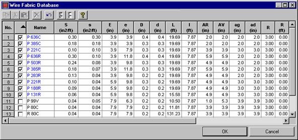
The wire fabrics viewer presented above is divided into two parts:
toolbar with icons
table presenting the data of the available wire fabrics.
The following data
are presented for each wire fabric type: the first three table columns provide
wire fabric number, information concerning the decision of taking the wire
fabric into account during calculations (if the option is selected - ![]() - the relevant wire fabric will be taken into
account; if not - it will not) and the wire fabric name. The successive table
columns provide the following information on the wire fabrics: reinforcement
cross-section [cm2/m], reinforcement spacing and diameter [mm], data concerning
bar ending parts and, if needed, the lap splice.
- the relevant wire fabric will be taken into
account; if not - it will not) and the wire fabric name. The successive table
columns provide the following information on the wire fabrics: reinforcement
cross-section [cm2/m], reinforcement spacing and diameter [mm], data concerning
bar ending parts and, if needed, the lap splice.
7 Final Drawings
The final drawings of the reinforcement calculated for RC elements constitute a separate Robot layout. This Robot layout contains specific options aimed at facilitating the manipulation of drawings. The most important ones will be discussed here.
Normal view (menu: View) - when a drawing of any element is called, the program enters automatically the drawing layout and opens the normal view. It is the general view of the contents of the entire drawing page. It does not allow one to insert, delete or modify the contents of the drawing. The mode under discussion is useful during the preparation of arrangement and composition of drawings for the final print-out format
Page set-up (menu: View) - this is the mode that allows one to correct the arrangement and size of elements of a drawing (the so-called viewport). Each element of a drawing is provided with handles at the corners that allow one to carry out edit operations. Once the modifications are completed, one should go to another display mode. Then, the program will regenerate the drawing and adjust the drawing contents to the newly-defined sizes of its elements.
Drawing components (menu: View) - this is the mode that displays the range of drawing elements and their contents. By indicating a given element of a drawing (it gets highlighted in red), one makes its contents ready to undergo editing process. Within the active area, one may carry out the following operations:
Þ change of the drawing scale and section position
Þ editing of the text (after indicating the text with the cursor and highlighting it in yellow) by calling the Edit text option from the context menu, available by pressing the right-hand mouse button
Þ deleting a text - after highlighting a text, one may delete it by pressing the DELETE button
Þ moving a text; after highlighting it, one should click the text, which changes the cursor shape to an arrow, by means of which one may move the text within the drawing element (viewport)
Þ editing the dimension (after indicating the relevant dimension with the cursor and highlighting it in yellow); by hooking the cursor at the end of a dimension, one may change its length, together with the value describing the dimension. In the case of dimension chains, the neighboring dimensions are changed together with the edited one
Þ deleting + moving the dimension lines (the option functions according to the same principle as text editing). In the case of moving a dimension, one may only move it parallel to the original position.
Þ adding a line, circle, text or dimension.
NOTE: After completing the editing process, one should press the ESC button in order to be able to go to editing of another drawing element (viewport).
Final print-out format (menu: View) - the option allows one to view the currently displayed drawings in a single common sheet of paper. Once the option is called, the program switches to another operation mode. The default final format is set to A4. In order to change the format size, one should call the Page setup option from the File menu and indicate the required paper format. Then, all the loaded drawings will be arranged automatically.
Automatic drawing arrangement (menu: View) - the option is responsible for
automatic arrangement of drawings in a big format and it operates in
cooperation with another option, described above. If the automatic drawing
arrangement does not meet the user's expectations, it is possible to switch the
option off. After indicating a required drawing (one should go to the
NOTE: In order to situate a drawing precisely in place, one should carry out the translation operation with the Ctrl button pressed.
Undo, redo (menu: Edit) - the options allow one to undo or redo the last operation. One should remember, however, that they bring, as a consequence, the loss of the possibility, for instance, of scaling the drawing elements (viewports) or inserting a summary reinforcement table
Cut, paste (menu: Edit) - these are standard options, operating for the entire drawing. By means of the options, one may cut any drawing and paste it in a different location, in a different page. The operation is of particular use during the arrangement of drawings in bigger formats, when the number of pages is larger than 1.
Drawing (menu: Insert) - if a drawing has been saved formerly as a project component, the option allows one to call and insert a drawing or a list of drawings. One should remember, however, that, after inserting a formerly saved drawing, it is not possible to scale it, neither is it possible to include it during the creation of a summary reinforcement table
New page (menu: Insert) - calling the option results in inserting a blank page with the format defined in the Page setup settings.
Table (menu Insert) - calling the option results in inserting a table for the drawings in a larger format. The table provided with the program (the default.lay file in the USR folder) is an example of a table; it may be modified or the user may define a new table by means of the PloEdit program
Summary reinforcement table (menu: Insert) - the option should be called after completing the changes of drawing arrangement in big format. It functioning consists in creating a summary reinforcement table, referring to the active drawings. When the table is being created, the program carries out automatic renumbering of all the reinforcement positions in the drawings.
PRINT-OUT IN LARGE FORMAT
In the case of a printer that does not support certain formats, the Page setup dialog box displays the formats that are supported by the currently installed printer. The remaining formats (not supported by the peripheral device) will be displayed, but their description will be shown in gray fonts. It is possible to carry out drawing arrangement for the 'gray' formats, but the preview and printing will be proceeded by the appropriate message: 'The selected format is not supported by the active printer'.
If there are printer controllers installed that service a printer that is not attached (physically) to the computer, the available formats defined by the installed peripheral device will be described in red. The preview and printout will also be proceeded by an appropriate message.
Final drawings are presented on screen according to the parameters accepted in the Drawing parameters dialog box. The option is used to select parameters of display, drawing presentation and detail drawing presentation for RC structure elements. The option may be run in one of the following manners:
by
pressing the Drawing parameters icon ![]()
by selecting the Analysis / Drawing parameters command from the menu.
The options available in the dialog box are used to define parameters of display and presentation of particular drawing fragments and the manner of behavior of drawings.
The dialog box consists of four tabs: General, Reinforcement description, Scale and Reinforcement table.
The above dialog box allows one to select the general drawing template. The first letters of the standard names of templates provided with the program refer respectively to:
bm - beams/continuous footings
bc - columns
bf - foundations
bs - slabs
bw - deep beams.
All the standard templates are located in the CFG folder created during Robot installation and they bear the *.plo extension. In order to modify an existing drawing template or open a new template, one should run the PLOEDIT program - the editor of drawing templates. The program is installed during Robot installation.
Once a template is selected for the module allowing one to design elements of RC structures, the right-hand part of the dialog box presents a preview of the template. Apart from template selection, the tab allows one also to set the mode (manner) of creating a drawing. Selecting the first mode (Open new) results in the presentation of only the drawing of the selected concrete element or the list of elements. Each time a drawing is called again, the former drawing is removed.
Selecting the Add drawing to the list mode changes the functioning and operation of drawings. If the option is selected, a drawing will not be removed after calling again a new one, but it will be added to a common list. The option is designed to allow one to create (compose) drawings of different elements (beams with columns, etc.) and to arrange them in a common, large-format sheet.
The Reinforcement description tab allows one to determine the manner in which reinforcement elements are described. Apart form the number of reinforcement position - always switched on - a drawing may display the following elements:
Number (of bars) + diameter - displays the number of identical bars and their diameter, apart from the reinforcement position number
Length - if the option is switched on, the program displays information concerning the total length of the selected reinforcement element
Spacing - in the case of beams, the spacing refers only to the splice reinforcement; in the case of columns, the spacing refers to stirrups in the central part of a column; in the case of foundations, the description of reinforcement spacing refers to the main reinforcement of the foundation; in the case of deep beams and slabs, the description of spacing refers to each reinforcement element in the form of a bar
The Longitudinal reinforcement description on the section option is created principally for beams. In the case of columns and deep beams, the program always displays descriptions of longitudinal reinforcement along a section; the option is not used in the case of footings and slabs.
The options provided on the Scale tab allow one to impose the manner of scaling of particular drawing elements:
if The same for all pages option is switched on, the same scale for entire pages of the drawing of one element are imposed; for instance, in the case of a beam comprising several spans that are presented each on a separate page, the option imposes identical scaling for all pages containing the drawing of the selected beam
if The same for elevation and section option is switched on, the program draws the element section and its view in identical scale
if The same for both directions on elevation option is switched on, the program will not apply two different scales to present an element along its length and along its height.
The options provided on the Reinforcement table tab allow one to define parameters of displaying the reinforcement table, i.e. to add or remove a selected column of the table.
|
Politica de confidentialitate | Termeni si conditii de utilizare |

Vizualizari: 4430
Importanta: ![]()
Termeni si conditii de utilizare | Contact
© SCRIGROUP 2026 . All rights reserved