| CATEGORII DOCUMENTE |
| Bulgara | Ceha slovaca | Croata | Engleza | Estona | Finlandeza | Franceza |
| Germana | Italiana | Letona | Lituaniana | Maghiara | Olandeza | Poloneza |
| Sarba | Slovena | Spaniola | Suedeza | Turca | Ucraineana |
DOCUMENTE SIMILARE |
||
|
||
REMOVING AND INSTALLING PISTON
The cylinder head is taken off, the crank bearing caps removed and the crank bearing studs screwed out. Carbon deposits on the inner surface of the top section of the liner are removed. The piston is in bottom dead center.
Sequence of operation 1 (removing)

1. Slip 6 protection hoses over the cylinder head studs.
2. Clean tap holes in pistons by use of screw tap and ratchet.
3. Screw down suspension device without guide (034.006) to piston. In doing so, screw down the hexagon bolts until they are seated in the piston with the hexagon nut the full way backed off. Next tighten the hexagon nuts until the suspension device is firmly tightened. Hang with rope on lifting gear.
4. Turn crank gear cautiously to approx. 45º before/after TDC
5. Mount slides on connecting rod.
6. Pull piston slowly by use of the hoist, screw guide bar as far as it will go into the suspension tool. Pull piston completely and set it down on wooden supports.
7. If necessary: remove piston pin retaining rings by use of pliers, push out piston pin and remove connecting rod from piston.
8. Check sliding flange in oil supply passage for piston for sticking and blow out space with the use of an air hose (all four discharge passage must be free).
Starting position
Piston has been cleaned, inspected and, if necessary, overhauled. Protection hoses are slipped over cylinder head studs. Crank gear has been set to approx. 45º before/after TDC.
Sequence of operation 2 (installing)
1. Fasten suspension device to piston (see sequence of operation 1, item 3) and hang with rope on lifting gear.
2. Lubricate piston rings and running surface of piston with clean lubricating oil.
3. Mount slides on connecting rod and if dismantled: insert connecting rod into piston, paying attention to the sliding flange; insert piston pin and secure it carefully by means of the 2 retaining rings.
4. Stagger piston, rings gaps 180º.
5. Turn piston, suspended from hoist, so that the stamped on engine serial no. and the cylinder no. are facing towards the engine outside of the V-engine (marks are also provided on the crank bearing body and the bearing cap).
Note: When installing a new connecting rod, stampmark engine serial no. and no. of cylinder into foot of connecting rod.
6. Check to see that carbon deposits at the top of the cylinder liner have been removed, if not, remove them.
7. Clean tensioning tool, check for damage and oil inside.
8. Place ring compressor in the middle of the ring belt area and tighten it until piston rings are compressed into their grooves to the cylinder diameter.
9. Move piston, suspended from hoist, over cylinder and lower connecting rod cautiously into cylinder liner, guiding the piston by the guide bar, until piston skirt enters the liner.
10. Cautiously lower piston further down, making sure that the connecting rod comes to seat exactly on the crankpin. The locating pin in the bearing shell must enter the groove in the connecting rod.
11. Remove rings compressor and check to see that the number on the connecting rod tallies with the cylinder no.
12. Remove slides on connecting rod and screw the parts of the slides together to prevent their getting lost.
13. Fit crank bearing shell.
14. Install crank bearing cap with bearing shell and tighten bolts.
15. Unscrew and remove suspension tool.
16. Mount cylinder head
Fitting order of piston rings (when new)
Note: For removal and fitting of piston rings, use of piston rings expanding pliers is a must.
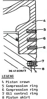
Fitted in the top-most groove of the piston crow (4) is a plasma-coated compression ring (5). The camfer on the inner diameter is always to face to the top.
Fitted in the second and third groove from the top, there are chromium-plated compression rings (taper face rings) (6). The camfers on the inner diameters are always to face to the top.
Fitted in the fourth rove from the top, there is an oil control ring (7) with coil spring.
 The
end gaps of neighbouring piston rings must be offset
to each other by 180 .
The
end gaps of neighbouring piston rings must be offset
to each other by 180 .
1. Piston without piston rings and piston pin
2. Piston skirt
3. Piston crown 13. Guide shoe
4. Thrust piece 14. Circlip
5. Stud screw 16. Piston pin
6. Hexagon nut 17. Lock ring
7. Clamping sleeve
8. O-ring A. Packing ring
9. Guide shoe B. Packing ring
10. Supply pipe C. Packing ring
11. Thrust spring D. Oil scraper ring
12. Washer
|
Politica de confidentialitate | Termeni si conditii de utilizare |

Vizualizari: 1351
Importanta: ![]()
Termeni si conditii de utilizare | Contact
© SCRIGROUP 2026 . All rights reserved