| CATEGORII DOCUMENTE |
| Bulgara | Ceha slovaca | Croata | Engleza | Estona | Finlandeza | Franceza |
| Germana | Italiana | Letona | Lituaniana | Maghiara | Olandeza | Poloneza |
| Sarba | Slovena | Spaniola | Suedeza | Turca | Ucraineana |
Design and Development of a Smart Vehicle for Inspection of In-service Water Mains
1Faculty of Engineering,
2School of Engineering,
Well functioning water networks are essential to the
sustainability of a community. Large transmission and distribution water mains
are often the most sensitive components of these networks since their failure
can be catastrophic. Furthermore, due to the high cost of these pipes, the
system does not usually provide redundancy to enable decommission for
maintenance and rehabilitation. For these reasons, failure of such water mains
often carries severe consequences including loss of service, severe damages and
water contamination. Aging
water mains often suffer from corrosion, tuberculation or excessive leakage.
These problems can affect water quality and decrease hydraulic capacity of the
mains contributing to water loss. In some cases, the main may be structurally
weak and prone to breakage. Consequently, modern urban centers need to
expend a considerable amount of financial resources on their repair and
renewal. However, the financial resources are often insufficient and a backlog
of necessary work accumulates. In
Prevention and/or early detection of such catastrophic failures needs a comprehensive assessment of pipe condition. A proactive inspection approach is critical to the condition assessment as well as cost-effective repair and renewal of water mains. Regular cyclic inspections can provide information on the physical conditions of the pipes and on the rates of material deterioration. Nondestructive/non-intrusive technologies for evaluating pipe condition are essential tools for the early detection. However, more research is required to adapt existing technologies to the unique circumstances of large water mains that cannot be taken off service.
In this context, an underwater robotic vehicle is designed to carry pipe inspection instruments including Nondestructive Testing (NDT) sensors used for inspection of in-service water mains of different materials. The robot can also provide real-time visual information about the interior surface of the pipe. The visual information and NDT data are synergistically used to make a more reliable decision about the condition of the pipe.
The on-board sensors would serve two purposes, namely (1) provide information for navigation and control of the robot, and (2) collect inspection data that can be post-processed. The proposed system has the following features:
It remains operational with pipeline in service.
It has a very simple structure (i.e., the minimum number of moving parts/actuators).
It is stable enough, throughout its motion, to maximize the performance of the inspection sensors.
The proposed design for the pipe inspection robot can suit pipes with inside diameters ranging from 6 to 10 inches. The proposed system allows for active condition assessment utilizing a variety of NDT methods to monitor defects such as mechanical damage, tuberculation, general wall loss, corrosion pitting, graphitization, cracks, reduced thickness of internal lining, and faulty joints. This can replace the traditional condition assessment methods, namely passive condition assessment, where only historical data are used to estimate the remaining service life of a pipe.
Conventional Inspection Methods
Statistical methods based on the number of pipe breaks per kilometer and reactive inspection techniques such as leak detection have been mainly used in the past for evaluation of water pipe condition. New testing technologies make it possible to develop more efficient and accurate approaches to maintain pipeline integrity through direct inspection. These techniques provide a variety of information about the condition of the pipes depending on their materials. Examples are the number of wires broken in a single section of the Pre-stressed Concrete Cylinder Pipe (PCCP), the depth of corrosion pitting in a ductile iron pipe, the extent of graphitization in a cast-iron pipe, or more generally the presence of leaking water [ ].
Pipeline Inspection Vehicles
Remotely operated or autonomous vehicles moving inside pipes that can deploy NDT techniques have been studied extensively for the past two decades. An exhaustive review of the literature is impossible due to the limited space available. However, various locomotion systems developed and cited in literature for in-pipe operations can be categorized into three main groups as follows:
Pipe Inspection Gauges (PIG): They are passive devices widely used for inspection of oil pipes and are designed so that sealing elements provide a positive interference with the pipe wall. Once inserted into a line, PIGs are driven through the line by applying pressure in the direction of required movement. A pressure differential is created across the PIG, resulting in movement in the direction of the pressure drop. Upon removal, the information logged using the PIGs onboard data storage unit is played back and analyzed. PIGs are normally employed for the inspection of pipelines with large diameters. Their inspection operations are limited to relatively straight and uninterrupted pipe lines operating in the high-pressure range. Short inspection runs are costly. Besides, the pipeline must be relatively clean for precise inspection, [e.g., 4, 5].
Floating systems/robots: Autonomous Underwater Vehicles (AUV) and Remotely Operated Vehicles (ROV) are oceanographic locomotion interfaces used for data acquisition in subsea and deepwater missions. The applicability of existing floating robots in the confined environments such as pipes will be very limited. Further modifications will be needed to make them suitable for inspection of pressurized pipelines, [e.g., 6, 7].
Mobile robots: significant effort has been put into devising an effective mechanism to drive a robotic system carrying on-board sensors/testing devices through different pipe configurations. The sensors on these robots must be small in physical size, lightweight, and low in power consumption as compared to the other systems mentioned above. Academic researchers and industrial corporations have investigated many variations of drive mechanisms such as wheels, crawlers, wall press, walking, inchworm, screw and pushrods. Some systems have complex mechanisms and linkages, which in turn require complicated actuation and control. Wheeled systems claimed the edge over the majority due to their relative simplicity and ease of navigation and control. Comparatively, they are able to travel relatively fast and far. However, most of the mobile robots developed for this purpose have been residential in research labs because of their lack of ability to move inside pressurized pipes [e.g., 8-11]. Some popular variants of mobile robots for pipe inspection are briefly described below.
Wheeled/tractor carriers: These are the simplest drive mechanisms that are targeted for inspecting empty pipes. These remotely controlled vehicles are designed to serve as platforms to carry cameras and navigate through pipes and conduits [ ].
Pipe crawlers: These are locomotion platforms that crawl slowly inside a pipeline. They can move down the pipeline independent of the product flow and maneuver past the physical barriers that limit inspection. They can even stop for detailed defect assessment. These robots are reconfigurable and can fit pipes with a variety of sizes [ ].
Helical pipe rovers: The robots developed at the University Libre de Bruxelles are considered as an example of a helical pipe rover (they are called HELI-PIPES). HELI-PIPE family consists of four different types of robots for in-pipe inspection. The robots have two parts articulated with a universal joint. One part (the stator) is guided along the pipe by a set of wheels moving parallel to the axis of the pipe, while the other part (the rotor) is forced to follow a helical motion thanks to tilted wheels rotating about the axis of the pipe. A single motor (with built-in gear reducer) is placed between the two parts (i.e., rotor and stator) to generate the forward motion (no directly actuated wheels needed). All the wheels are mounted on a suspension to accommodate for slight changes in pipe diameter and also the curved segments of the pipe. These robots are autonomous and carry their own batteries and radio links. Their performance is, however, limited to very smooth and clean pipes [ ].
Walking robots: Wall-climbing robots with pneumatic suction cups and/or electromagnets have been used for inspection of vertical pipes, conduits, and steel structures [ ]. Walking robots are particularly useful for inspection of irregular and rough surfaces [e.g., 18].
Pipe inspection robots can be configured as tethered or wireless. They can be controlled remotely, or being totally autonomous. To the best of our knowledge, all existing pipe rovers are for inspection purposes only. In general, current mobile robotic systems are not yet adequate for on-the-fly repairs in a complex pipe environment.
Development of the locomotion unit of a robot capable of inspecting in-service pressurized pipes remains a very challenging and novel research topic. Moreover, precise control of such a pipe inspection robot when subjected to flow disturbances necessitates development of nonlinear control strategies. This study addresses the mechanical design of a pipe crawling robot capable of moving inside pressurized pipes and a fuzzy-logic based control strategy to maintain a constant speed for the robot when moving inside live pipes.
3.1 Design Factors
Major factors considered in the design of the proposed pipe inspection robot are reviewed in this section. The principle objective put into practice in our design is to build a vehicle to serve as a highly stable platform capable of conducting precise sensing/scanning actions. The stability of the platform in terms of having smooth motion with regulated cruise speed is necessary for accommodating sensor readings at a high bandwidth. Precise positioning of the vehicle is particularly important for using precision probes to inspect and evaluate the condition of the inner surface of the pipes. The main design requirements of the robot are as follows:
The vehicle should be capable of completing inspection without decommissioning the pipeline.
The vehicle has to be pressure tolerant up to 20 atmospheres.
a. Freshwater transmission lines are operated at pressures of up to 16 atmospheres, therefore with a reasonable margin of safety we require the vehicle to be able to operate at 20 atmospheres, which corresponds to the hydrostatic pressure experienced at 200 m of depth in open water.
The sensor payload of the vehicle has to be flexible and user interchangeable.
a. The primary use of this vehicle is to carry a number of NDT sensors that are in various states of development. It is therefore necessary for the user to be able to swap and replace sensors within hours.
Autonomy of the inspection process.
a. The length of the survey (several kilometers) makes a tethered vehicle impractical.
b. Very detailed inspection should be done autonomously.
The robot should be designed in a way that it will not deteriorate the sanitation of the drinkable water when used in distribution water pipes.
The vehicle should be capable of traveling with any inclined pipe angle. The vehicle shall have the ability to travel vertically, negotiate multiple elbows, and potential obstacles protruding into the pipe up to 1/3 of the pipe diameter.
Travel speeds should be a minimum of 3 centimeters per second, with 30 centimeters per second as the desirable speed.
Finally, the vehicle should be able to stop and position itself at a specific location within the pipe using its onboard internal sensors, such as optical encoders.
In our proposed system, we use a low drag cylindrical shape hull as a platform for carrying inspection/navigation sensors and NDT devices. The symmetric shape of the hull can maintain a laminar boundary layer around the hulls outer surface. The low-drag property of the main body enables the system to show superior stability against current in the pipe without loosing too much energy which is necessary in minimizing the size of the on-board battery pack required to travel long distances.
The hull consists of the following modules:
Nose Module This module accommodates a viewport for a digital still or a video camera.
Rechargeable
Actuator, Control and Communication Module it accommodates the vehicles actuator along with the control and communication electronics. Control instrumentation includes a 3-axis magneto-inductive compass, inclinometers, a temperature sensor, and an optical encoder. Communication is done via Bluetooth wireless module for short distances. For distances longer that 30 meters, the controller switches to autonomous operation. The actuator consists of a geared DC motor.
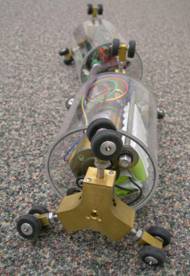
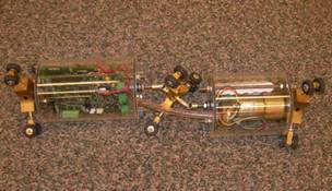
The main hull houses the actuator and the battery pack. The electronics responsible for power conversion, communication to the wireless transceiver, sensor integration, and various electric motor controls is housed in the second module connected to the main hull via a universal joint (see Figure 1a-1b). Further details on the design of the proposed robot can be found in [19].
Controller DC motor Universal joint Passive
straight wheels Angled wheels![]()
![]()
![]()
(a) (b)
Figure 1: The pipe inspecting robot. (a) active and passive wheels, (b) the actuation and control modules.
There is one set of driving wheels located at one end of the hull, pushing against the pipe inner wall. These wheels are spring-loaded (see Figure 1). The driving wheels are approximately 4 centimeters in diameter with aluminum hubs and rubber tires. The tires have treads to provide additional traction. Larger compliant tires are appropriate for bumps and uneven internal surfaces. The driving wheels are actuated by a central geared DC motor which provides forward propulsion for the robot. The on-board electronics will be responsible for producing, filtering and controlling the power delivered to the motor for safe operation. Friction between the passive straight wheels attached to the hulls back end and the pipes wall, prevents the hull from spinning while the main actuator is providing smooth forward motion in the pipe.
Figure 2 shows a simplified representation of the robots driving mechanism. One should note that, (1) only a pair of driving wheels are considered, and (2) the passive straight back wheels are not shown in this figure for simplicity. As can be seen from Figures 1 and 2, the driving wheels are positioned at a small angle with respect to the vertical plane of the hull. The wheels are pushed against the inside wall of the pipe and driven along the circumference of the pipe. In this way, they generate a screw-type motion and move along the pipe. This mechanism, as schematically illustrated in Figure 2, is analogous to a large screw being turned inside the pipe and consequently moving forward. When a reverse driving torque is applied to the wheels, the robot runs backward in the pipe.
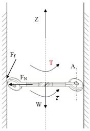
Figure 2. The drive mechanism of the robot based on the principle of screw.
This design provides simplicity and compactness with minimal blockage of live pipes. Our proposed robot can negotiate pipes composed of straight and curved segments.
Three different types of sensors are incorporated into the design, namely (1) navigation, (2) communication, and (3) inspection sensors. However, some sensors potentially can be employed for both navigation and inspection. An optical encoder reading motors shaft displacement was used for localizing the robot inside the pipe. A vision sensor (i.e., a pinhole camera) along with an Omni-directional Stereo Laser Scanner (OSLS) were employed for navigation/inspection purposes. Unbounded position errors due to slippage in wheels is inevitable, therefore the OSLS can be superior over optical encoders to precisely measure lateral translational motion of the robot, namely, sway and two rotational motions, namely pitch and heave, [20]. A sensor fusion strategy would be required to integrate orthogonal information coming from different sensing units as the robot moves. It is also noteworthy that some temperature sensors were used in each module to continuously monitor the temperature build up in each water-tight unit.
In this section the kinematics and kinetics of the proposed robot moving inside a vertical straight pipe is investigated. The development of the mathematical model of the robot leads to a full understanding of all of the key elements of the system needed before devising a controller. For simplicity, the dynamics equations are derived based on the assumption that (1) there is only one pair of driving wheels, (2) the angle of the driving wheels cannot change on fly, and (2) the wheels apply a fixed amount of normal force to the pipes wall preventing the slippage (i.e., no on-fly extension in arms applied as the robot moves). One should note that assumption (1) can be relaxed without loose of generality.
The vehicle model and coordinate systems used in this study are shown in Figure 3. It is assumed that one DC motor drives the hub and accordingly the wheels attached to the hull (or main body), as the prime actuator. From Figure 3, frames i, B, and W represent the inertial fixed frame, the body frame attached to the main body of the robot, and the wheel frame attached to the wheels center of rotation, respectively.
![]()
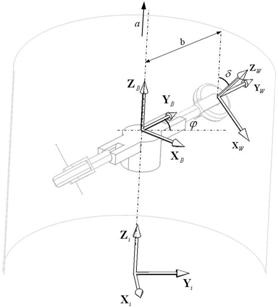
Figure 3: The simplified model of the robot, with one pair of driving wheels, showing three reference frames.
In the presented dynamics model of the robot the following parameters are used:
4.1 Kinematics
It can be easily shown that the translational
velocity of the hulls COG, ![]() can be related to the wheels inclination angle,
can be related to the wheels inclination angle, ![]() wheels radius of
rotation, r, and the rotational speed of the wheel,
wheels radius of
rotation, r, and the rotational speed of the wheel, ![]() as follows:
as follows:
![]() (1)
(1)
Correspondingly, the rotational speed of the hull, ![]() can be related to that
in wheels as follows:
can be related to that
in wheels as follows:
 , (2)
, (2)
where b denotes the distance between wheels center of rotation and that for the hull (see Figure 3).
4.2 Dynamics
The dynamic equations of motion of the robotic vehicle can be derived following the standard Lagrangian approach. In this approach, first the Lagrangian L has to be calculated as follows:
![]()
where T and V denote the kinetic energy and the potential energy due to gravitational forces, respectively. The total kinetic energy of the robotic vehicle can be represented by:
![]()
where THull and TAngled_wheel denote kinetic energies of the hull and the wheels, respectively. In Eqn. (4), the kinetic energy of the passive straight wheels is disregarded. The THull can be readily calculated as:
![]() (5)
(5)
The TAngled_wheel can be calculated as follows :
![]() , (6)
, (6)
Where IWZ denotes the polar moment of inertia of the
wheel about its axis of rotation, IWX represents the moment of inertia of the wheel
about its diameter. Also, in Eqn. (6), ![]() and
and ![]() represent the short form of
represent the short form of ![]() and
and ![]() , respectively. Considering equations (2), (5) and (6), the
total kinetic energy of the system can be written as:
, respectively. Considering equations (2), (5) and (6), the
total kinetic energy of the system can be written as:
![]()
where,
![]() (8)
(8)
The potential energy of the robot due to the gravity when moving in a vertical pipe can be calculated as:
![]()
Where g represents the gravitational acceleration.
The Lagranges equations are expressed as follows:
![]()
Where ![]() denotes the generalized coordinates, and
denotes the generalized coordinates, and ![]() denotes the
generalized active forces associated with the generalized coordinates,
denotes the
generalized active forces associated with the generalized coordinates, ![]() . Considering the angle of rotation of the wheel, θ
as the only generalized coordinate in the Lagrange formulation, one can write:
. Considering the angle of rotation of the wheel, θ
as the only generalized coordinate in the Lagrange formulation, one can write:
![]()
The generalized forces Q applied on the robot moving inside the pipe can be given as:
![]() (12)
(12)
Where the right hand side of the above equation represents the non-potential generalized torques such as motors torque, Tm and the resisting torques due to the dry friction between the wheels and their axles, Tf , and the resisting torque due to hydrodynamic drag force posed on the system via the flow inside the pipe, TD all projected onto the generalized coordinate, q.
Friction plays a significant role in creating the motion of the robot. The robot wheels roll due to the translational friction between the wheels and the internal surface of the pipe. Insufficient friction at the point-of-contact between the wheels and the pipes wall leads to wheel slippage. The slippage constraint of a wheel is expressed as (using Coulombs friction law):
![]()
Where denotes the friction coefficient, and FN denotes the the normal force applied on the internal surface of the pipe by the robots wheels. Therefore, the resisting torque due to the internal friction can be obtained from the following equation:
![]()
Where d represents the diameter of the wheels hub.
The hydrodynamic drag force induced by the flow on the robot, projected onto the generalized coordinate q, can be expressed as follows:
![]()
In Eqn. (15), r denotes the density of the water, A is the effective cross sectional area of the robot, v denotes the effective velocity of the flow inside the pipe, and Cd represents the drag coefficient . By substituting Eqns. (14) and (15) in Eqn. (12), the generalized force Q will be computed as:
![]()
By using Eqn. (16) and substituting T and V from Eqns. (7) and (9) into Eqn. (11), the following closed form solution in form of a nonlinear 2nd-order differential equation for the wheels motion (and correspondingly the robots motion) can be obtained:
 , (17)
Where h in Eqn. (17) is the same as that given in Eqn. (8). From Eqn. (17), one can realize that the motion of the robot can be controlled by changing parameters such as the wheels inclination angle, d the normal force exerted on the pipes wall via the wheels, FN, and the torque applied to the wheels actuators, Tm. The only control input that can vary on fly in our design is the motors torque, namely Tm. How to manipulate this torque in order to maintain a constant speed of motion when the robot is subjected to flow disturbances (i.e., variation in the flow speed, v) will be discussed in Section 5.
4.3 Motor Dynamics
Motor dynamics has been considered in our model which is briefly discussed in this section. The mechanical torque generated by a Permanent Magnet DC (PMDC) motor can be related to its input voltage and current through the following equation, [21]:
![]()
where Kt is the motors torque constant and ia denotes the armature current. For a PMDC one can also write:
![]() (19)
(19)
Where La denotes the armatures inductance, Ra denotes the armature copper resistance, and eb denotes the Back ElectroMotor Force (BEMF). The input voltage (i.e., the control variable) is denoted by ea in Eqn. (19). The BEMF is related to the rotational speed of the motors shaft as:
![]()
where Kb represents the BEMF constant. By incorporating Eqns. (18-20) into Eqn. (17), one can take the motors dynamics into account when controlling the robots speed subjected to flow disturbances
The above mathematical model was created and implemented in a MATLAB/Simulink environment. An overview of the systems model in Simulink is presented in Figure 4. The motion of the robot was also presented in a virtual reality environment. A snapshot of the implemented graphical simulation is also shown in Figure 5.
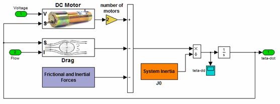
Figure 4: The systems model in MATLAB/SIMULINK
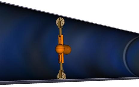
Figure 5: Visualization of the robot moving inside a pipe.
A user can control the motion of the robot by either changing the normal force FN and/or the wheels inclination angle, d offline, or by changing the input voltage provided to the DC motor on fly. A real-time interactive interface was implemented in MATLAB/Simulink, by making use of the real-time workshop toolbox from Mathworks, [22], for verification of the design in a human-in-the-loop control fashion. The performance of the human-controlled system in real time can be further used to optimize the performance of a stand-alone and autonomous controller such as a Fuzzy-Logic based controller offline. A stand-alone fuzzy-logic controller was utilized for speed control of the robot at this stage.
A control strategy based on Fuzzy-Logic was adopted. The controller strives to reject flow disturbances by maintaining a constant speed for the robot. A disturbance, in the form of step changes in flow velocity, is generated randomly as the robot moves in a simulated environment. The controller tracks the response of the system to its user-defined velocity set-point and sends a correction command in terms of the input voltage provided to the DC motor actuators. The overall control scheme is shown in the Figure 6.
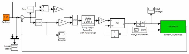
Figure 6: The fuzzy-logic based control scheme modeled in Simulink.
Fuzzy logic controllers incorporate heuristic control knowledge in the form of if-then rules, and are a convenient choice when a precise linear dynamic model of the system to be controlled cannot be easily obtained. They have also shown a good degree of robustness in face of large variability and uncertainty in the system parameters, [ ].
5.1 Description of the Proposed Control Logic
There are two main approaches to fuzzy control, namely the Mamdani method and the model-based fuzzy control, [24, 25]. We have adopted Mamdanis in our studies. Central to the design of a Mamdani fuzzy control are: (1) fuzzification of crisp variables using membership functions along with application of implication and aggregation methods, (2) defining an if-then rule-base, and (3) the defuzzification. In our proposed fuzzy control the inputs are the error between robots linear velocity inside the pipe and its desired value, and its rate of change. Triangular membership functions were utilized for fuzzification and defuzzification phases. The fuzzy logic controller adjusts the control variable, namely the input voltage provided to the wheels actuators in order to maintain a constant speed in the robot when subjected to flow disturbances. Table I shows the rule base and fuzzy implication for the error in the system and its rate of change. The error and its rate of change could assume the following values: Positive (P), Positive Large (PL), Zero (Z), Negative (N), and Negative Large (NL). The control values are tabulated in Table I.
The controller is designed using five membership functions for each input variable (i.e., error in linear speed and its rate of change) and that for the control variable.
Table I: Fuzzy rule base.
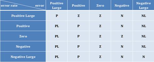
The fuzzy rules were extracted through the implementation of a real-time human-in-the-loop virtual reality simulation environment, [26]. It was then conjectured that the simple rule base provided in Table I would suffice to reject flow disturbances in form of step changes in flow velocity within a user-set design objective.
The membership functions assigned to the error in system are shown in Figure 7. Similar membership functions were implemented for the rate of change of the error in the system as well. The range of error is limited to 0.8 m/sec. Correspondingly, the rate of change in error has been limited to 5 m/sec2. The normalized membership functions associated with the control variable (motor voltage) is represented in Figure 8. As can be seen from Figure 8, the control variable can become Negative Large (NL), Negative (N), Zero (Z), Positive (P), and Positive Large (PL).
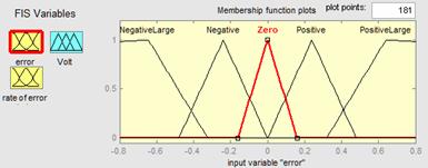
Figure 7: Errors membership functions.
Figure 8: Control variables membership functions.
6. Simulation Results
Computer simulations were conducted to show the robustness of the FL-based controller in rejecting flow disturbances. The desired linear speed of the robot was set at 0.15 m/sec. A flow disturbance in form of step changes in flow velocity were synthesized (see Figure 9). As can be seen from Figure 9, there is no flow for the first 10 seconds of simulation. There is a step increase in flow velocity from 0 to 2 m/sec at t = 10 seconds and a step decrease from 2 m/sec to 1 m/sec at time t = 20 seconds. Figures (10-11) show the variation of the error signal and its rate of change versus time. The rise time of the controller is ~1.1 seconds with a settling time of ~2 seconds when the system being subjected to step changes in flow velocity. The rate of change of the error signal decays to zero within a reasonable time as well. Figure 12 shows the robots linear speed versus time. The controller can reject flow disturbances quite fast with reasonable under/overshoot. Figure 13 shows the 3D error surface of the FL-based controller. Manufacturers specification of a Pittman servo motor were utilized in the simulations, [27].

Figure 9: Flow disturbance in form of step changes in flow velocity.

Figure 10: Time response of error.
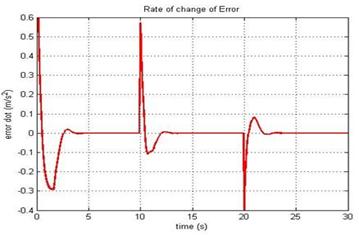
Figure 11: Rate of change of the error.
Desired speed Robots linear speed inside the pipe
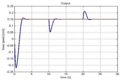
Figure 12: Time response of the robots linear speed.
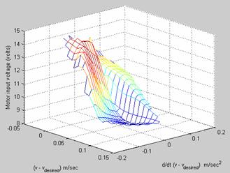
Figure 13: The 3D error surface of the FL-based controller.
7. Conclusions and future work
This paper addressed the preliminary design of a robotic system for active condition assessment of in-service water pipes. The robot has a very simple driving mechanism. By utilization of angled wheels on the robot one can generate a screw-type motion. The robot can move against gravity. Besides, the proposed robot will be able to better negotiate curved sections of the pipe as opposed to that in existing robots with straight wheels.
A Fuzzy-Logic (FL) based controller was developed and its performance was depicted in a representative computer simulation. The FL-based control strategy can meet the design requirements, namely fast and precise control of the robots linear speed when subjected to flow disturbances (i.e., pressure fluctuation inside the pipe, flow velocity, etc.). The FL-based control strategy was simulated in real-time utilizing a comprehensive dynamics model of the robot.
Future work has three folds as follows: (1) using an Adaptive-Network-Based Fuzzy Inference Systems (ANFIS) to tune the FL-based controller parameters/rules to optimize its performance. In this context, a dynamic real-time human-in-the-loop simulation has been developed where a human (expert) could physically control the motion of the robot through visual feedback in real time. The proposed fuzzy-logic controller will be then further optimized to match the experts performance adaptively depending on application domain, (2) design and fabrication of a real prototype with extending arms to fit a variety of pipes with different sizes, and (3) developing a Hardware-In-the-Loop (HIL) simulation system, as depicted in Figure 14, to control the motion of the robot when located in an empty pipe (or duct) in a dry lab. A motorized flow simulator will be employed to simulate the effect of hydrodynamic forces exerted on the robot as it were moving inside a live pipe. The flow simulator and the robot will be connected via force sensors.
Pipe
Robot
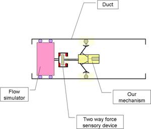
Figure 14: The proposed HIL simulation system.
Appendix A: Dynamics Model of the Proposed Pipe Inspecting Robot (the kinetic energy of the robots wheels).
In order to derive the dynamics model of our proposed system, three coordinate frames, as shown in Figure 3, are taken into consideration which are as follows:
One should note that the extension of robots arms is not considered in the dynamics model for simplicity. Transformations from the wheel- and body-fixed coordinate frames to the inertial reference frame are described here. The general orientation of the wheel-fixed frame (hereinafter called wheel frame) represented in the inertial frame can be utilized through a number of successive rotations called Euler Angles. The relative rotation between the wheel frame and inertial frame can be represented as follows:
 (A1)
(A1)
where
 (A2)
(A2)
 (A3)
(A3)
In Eqns. (A1-A3), f,
q,
and d
denote the rotational angle of the robots body with respect to the inertial
frame, the rotational angle of the wheel with respect to the body frame, and
the inclination angle of the wheels, respectively. One should note that the
following notation is used in long equations; ![]() , and
, and ![]()
Total kinetic energy of each robots wheel can be calculated as follows:
![]() (A4)
(A4)
where ![]() ,
, ![]() , m, and iIW denote the
linear velocity of the origin of the wheel frame represented in the inertial
frame, the angular velocity of the wheel frame represented in the inertial
frame, the wheels mass, and the wheels inertial tensor represented in the
inertial frame, respectively. These
terms are described below in more detail.
, m, and iIW denote the
linear velocity of the origin of the wheel frame represented in the inertial
frame, the angular velocity of the wheel frame represented in the inertial
frame, the wheels mass, and the wheels inertial tensor represented in the
inertial frame, respectively. These
terms are described below in more detail.
One can write:
![]() , (A5)
, (A5)
where ![]() denotes the velocity of the origin of the body frame
represented in the inertial frame,
denotes the velocity of the origin of the body frame
represented in the inertial frame, ![]() denotes the relative velocity of the wheel frame and body
frame represented in the inertial frame,
denotes the relative velocity of the wheel frame and body
frame represented in the inertial frame, ![]() denotes the angular
velocity of the body frame represented in the inertial frame, and
denotes the angular
velocity of the body frame represented in the inertial frame, and ![]() denotes the vector connecting the origin of the body frame to
the origin of the wheel frame represented in the inertial frame. One can
readily conclude:
denotes the vector connecting the origin of the body frame to
the origin of the wheel frame represented in the inertial frame. One can
readily conclude:
![]() (A6)
(A6)
and:
![]() (A7)
(A7)
With
the assumption that the robots arms are fixed, namely b = 0 (see Figure
6), one can conclude: ![]() = 0T.
One can also write:
= 0T.
One can also write:
![]() (A8)
(A8)
After substituting Eqns. (A6-A8) into Eqn. A5, one gets:
![]() (A9)
(A9)
Correspondingly, the angular velocity of the wheel frame represented in the inertial frame can be calculated as follows:
![]() , (A10)
, (A10)
where ![]() denotes the relative angular velocity between the wheel frame
and that for the body frame represented in the inertial frame. One can write:
denotes the relative angular velocity between the wheel frame
and that for the body frame represented in the inertial frame. One can write:
![]() (A11)
(A11)
By substituting Eqns. A7 and A11 in A10 one can write:
![]() (A12)
(A12)
With the assumption that the wheel assembly has a symmetric mass distribution about its axis of rotation and with the assumption of small wheels inclination angle, d, its inertia tensor expressed in the inertial frame can be calculated as follows:
 (A13)
(A13)
Where the diagonal of
the inertia matrix given in Eqn. (A13) denotes the moment of inertia of the
wheel around the X, Y, and Z axes of the wheel frame, respectively. One should
note that![]() .
.
By substituting Eqns. (A9), (A12), and (A13) in Eqn. (A4), one can derive:
![]() (A14)
(A14)
One should note
that the kinematics constraint of ![]() , applicable under no slippage condition on robot wheels, was
utilized to derive Eqn. (A14) as well. Eqn. (A14) can be further simplified for
small inclination angles of the wheels, d in which case one can
assume; sin(δ) 0 and cos(δ) 1 as follows:
, applicable under no slippage condition on robot wheels, was
utilized to derive Eqn. (A14) as well. Eqn. (A14) can be further simplified for
small inclination angles of the wheels, d in which case one can
assume; sin(δ) 0 and cos(δ) 1 as follows:
 (A15)
(A15)
Grigg, N. S. Condition Assessment of Water Distribution Pipes, Journal of Infrastructure Systems, Sept. 2006, Vol. 12, Issue 3, pp. 147-153.
Eiswirth M., Frey C., Herbst J., Jacubasch A., Held I., Heske C., Hotzl H., Kuntze H.-B., Kramp J., Munser R., and Wolf L. Sewer Assessment by Multi-sensor Systems, 2nd World Water Congress, Berlin, Germany. October 2001.
Gummow, R. A., Corrosion and Cathodic Protection of Pre-stressed Concrete Cylinder Pipes, Materials Performance, Vol. 44, Issue 5, pp. 32-33, May 2005.
Shiho, M., Horioka, K, et. al, Proposal for Environmental Observation System for Large Scale Gas Pipeline Networks using Unmanned Airship, 2nd International Symposium on Beamed Energy Propulsion Proceedings, Issue 702, pp. 522-533, 2004.
Nguyen, T. T., Yoo, H. R., et. al. Speed Control of PIG using Bypass Flow in Natural Gas Pipeline, IEEE International Symposium on Industrail Electronics Proceedings, Vol. 2, pp. 863-868, 2001.
Gwyn Griffiths, Technology and applications of autonomous underwater vehicles, published by Tylor & Francis Inc., 2003.
F. Nickols, R. Bradbeer, and S.O. Harrold, An
Ultrasonically Controlled Autonomous Model Submarine Operating in a Pipe
Environment, IEEE Conference on Mechatronics and Machine Vision, Proceedings,
Koji, K. Underwater inspection robotAIRIS 21, Journal of Nuclear Engineering and Design, Vol. 188, Issue 3, pp. 367371, May 1999.
Roh, S., and Choi, H. R., Differential-drive In-pipe Robot for Moving Inside Urban Gas Pipelines, IEEE Transaction of Robotics, Vol. 21, Issue 1, pp. 1-17, February 2005.
https://www.kanalrobotik.de/de/r_pipe_rover.html (last visited, July 2007)
Miwa Y., Satoh S., Hirose N., Remote-controlled Inspection Robot for Nuclear Facilities in Underwater Environment, 10th International Conference on Nuclear Enginering, 2002.
https://www.inuktun.com/ (last visited, July 2007).
https://www.netl.doe.gov/technologies/oil-gas/publications/td/NT41881_FinalRpt.pdf (last visited, July 2007).
Bradbeer, S. Harrold, Luk, B.L., Li, B., Yeung L.F.,
and Ho H.W. A Mobile Robot for Inspection of Liquid Filled Pipes, Workshop
on Service Automation and Robotics,
M. Horodinca, I. Doroftei,
https://www.ulb.ac.be/scmero/robotics.html#pipe (last visited, July 2007).
S.W. Glass, M.L. Levesque, G.J. Engels, F.C. Klahn, and D.B. Fairbrother, Under-water Robotic Tools for Nuclear Vessel and Pipe Examination, Framatome Technologies, Lynchburg Virginia, https://www.rovtech.com/news/95.html (last visited, June 2007).
https://www.cityu.edu.hk/applied_research/electronics/FSE_EE_RobinBradbeer_02.html (last visited, July 2007).
Ratanasawanya, C., Binsirawanich, P., Yazdanjo, M.,
Mehrandezh, M., Poozesh, S., Paranjape, R., and Najjaran, H., Design and
Development of a hardware-in-the-loop Simulation System for a Submersible Pipe
Inspecting Robot, Proc. Of the 2006 IEEE Canadian Conference on Electrical and
Computer Engineering (CCECE06),
Kulpate, C., Mehrandezh, M., Paranjape, R., Najjaran, H., Design and Development of a Stereo Laser Scanner for Condition Assessment of Water Pipes, Faculty of Engineering, University of Regina, Technical report UR/CSIR-01-2006, November 2006.
Sen, P. C., Principles of Electric Machines and Power Electronics, 2nd edition, John Wiley $ Sons, 1997.
https://www.mathworks.com/ (last visited, July 2007).
Alessandro Saffiotti, 'Using fuzzy logic for autonomous robotics: an on-line workshop', The knowledge Engineering Review, Vol. 12, Issue 1, pp. 91-94, 1997.
Mamdani, E. H. 'Application of Fuzzy Logic to Approximate Reasoning using Linguistic Synthesis', 6th International Symposium on Multiple-valued Logic, Proceedings, Logan, Utah, USA, pp. 196 - 202. 1976.
Nguyen, H. T., Prasad, N. R., Fuzzy Modeling and Control: Selected Works of Sugeno, CRC Press, 1999.
Mehrandezh, M., Poozesh, S., Paranjape, R., and Najjaran, H., Design and Development of Real-time Virtual Reality Simulation Environment for the Position/Velocity Control of the Regina Pipe Crawler, Technical report, Faculty of Engineering, University of Regina (Mechatronics lab), UofRML-02-2006.
https://www.clickautomation.com/products/index.php?func=list&cid=3 (last visited, July 2007).
|
Politica de confidentialitate | Termeni si conditii de utilizare |

Vizualizari: 3310
Importanta: ![]()
Termeni si conditii de utilizare | Contact
© SCRIGROUP 2026 . All rights reserved