| CATEGORII DOCUMENTE |
| Bulgara | Ceha slovaca | Croata | Engleza | Estona | Finlandeza | Franceza |
| Germana | Italiana | Letona | Lituaniana | Maghiara | Olandeza | Poloneza |
| Sarba | Slovena | Spaniola | Suedeza | Turca | Ucraineana |
|
Full IP Wireless Networks Planning Methods |
Abstract Planning or network design receives special attention in modern communication systems. The costs of building a wireless network are colossal especially because of the frequency bands which represent a limited resource. A network badly designed would need optimization solutions that mean new investment. Even with the new investments, the effects cannot be guaranteed. Taking these into consideration, a good dimensioning from the design phase is important to bring benefits to the operator and for the tuning and optimization to have effect.
|
T |
HIS document presents the theoretical issues related to Planning Methods in Full IP Wireless Networks. The starting point is represented by WirelessMAN technology Wireless Metropolitan Area Network (a.k.a. WiMAX Worldwide Interoperability for Microwave Access).
The purposes of WiMAX technology are to provide large amounts of data over long distances for a variety of services using from point to point links to cellular based network designs and the most important: the data is provided wireless.
There are no general planning methods for building wireless networks. Mostly methods are specific depending of a lot of factors like traffic quantity or geographical positioning.
A wired environment offers a guided link, viable that can lead an electrical signal associated with an information transmission from a fixed terminal to another. Wires act as a filter that limits the maximum transmission rate because of the limited frequency response of the channel. The extension of the band can easily be achieved by adding more wires.
In comparison with the wired environment, the wireless environment is not reliable, have a narrow frequency band, and have a broadcast character but they offer mobility. In wires, different signals are physical located in different wires but in wireless case all transmissions share the same environment the air. The operating frequencies are around 1GHz (cellular systems), 2GHz (PCS, WLAN), 5GHz (WLAN), 28-60 GHZ (Local Multipoint Distribution Services [LMDS]), IR frequencies for optical communications. Usually before using a frequency band a license must be bought; there are bands that do not require license. As the frequency increases, the cost of equipment increases also and the degree of signal penetrating building walls decreases. Because of the evolution of integrated circuits, the equipment cost is less than the cost for licenses.
In case of extending frequency band in wireless theres nothing that we could do. There have been developed methods for increasing capacity so a fixed bandwidth could serve more users. The simplest method is used in cellular systems by reusing frequencies. For further increasing capacity the size of the cells could be reduced. This method allows even more users but then again the infrastructure cost increases.
The radio signals having frequencies greater than 800MHz, used in wireless networks, have extremely small wavelengths so the electromagnetic waves can be treated as rays.
Reflection and Transmission. These phenomena appear when the waves encounter obstacles much larger then their wavelength. Because of these phenomena one ray is attenuated with a coefficient that depends on the frequency, incidence angle and the nature of the environment.
Diffraction. This phenomenon appears to incident rays on the edges of the buildings, walls or other large objects. These objects can be seen as a new signal source. The benefit would be the coverage of signal shadowed areas. Because of the diffraction (especially the fact that the second source is created) large losses appear larger than in the case of reflection or transmission. However the diffraction is important because of the mentioned advantage.
Scattering. Irregular objects like rough walls, furniture, vehicles, foliage cause the scattering of rays in all directions as spherical waves. This phenomenon appears when the size of the irregularities is close to wavelength or smaller. The waves propagated thru scattering have very low power, but this phenomenon is taken into consideration only in areas where the number of causing objects is big. In cellular networks the most significant factor is the foliage.
Depending of the receiver environment, the received power for the same distance between the transmitter and the receiver but in different locations wont be the same. This phenomenon is called slow fading or shadow fading. Shadow fading because the variations are given by the positioning of the receiver behind the walls so there is no direct line of sight. It is called slow fading because the loss with distance is smaller than in other cases of fading. This kind of fading that refers to mean values from measurements is called large scale fading. In reality the received signal has rapid fluctuations because of the mobility of the terminal and a lot of signal components arrive on different roads. These rapid fluctuations refer to small scale fading and are caused because of the mobility of the receiver or the surrounding objects.
The OFDM (Orthogonal Frequency Division Multiplexing) technology combines three transmission principles: multirate, multisimbol, and multicarrier modulation. The name of the technology comes from the method of implementation MCM, using the orthogonal adjacent carriers. A MCM system is actually an FDM (Frequency Division Multiplexing) in which a single user uses all FDM channels in the same time. OFDM is an implementation of MCM which takes advantage of the cannel ortogonality and is implemented using a FFT algorithm.
MCM concept is very simple: instead of modulating a single carrier at a certain R rate (symbols/sec), we use N carriers distanced at approximately R/N Hz and modulate each at R/N symbol/second rate. The advantage of this trick is that in case of a multipath channel the multipath effect is reduced relatively to the duration of one symbol so N times more reduced distortions in each received symbol. Another MCM advantage: by using subchannels we achieve frequency diversity and the effects of the frequency selective fading are smaller. Further we can measure the signal in different subchannels and using a feedback channel to adjust the power on the affected subcarriers. We conclude that the multicarrier transmission is a simple alternative to the singlecarrier transmission that requires complicated receivers. Also it is a good solution for wide band transmissions because the issue of increasing the bandwidth is solved by increasing the number of subcarriers. The limitations appear at implementation complexity and at the transmitted power.
2) Multisymbol Modulation
This type of modulation uses the modulation of more amplitudes and phases and also uses coding techniques for improving the data rate. The traditional QPSK (Quadrature Phase Shifting Keying) modems use a 4-symbol constellation, for each symbol 2 bits are send. The main advantage of using multisimbol transmission is the increasing of the data rate for the same bandwidth.
For example by using QPSK modulation the transmission is doubled then the case of BPSK (Binary Phase Shifting Keying ) transmission.
Further increases of data rate can be obtained by increasing the symbol constellation by using more amplitudes and phases. These symbols are then modulated using a QAM (Quadrature Amplitude Modulation) modem that transmits the imaginary and real part of the symbol using the in phase and in quadrature signals.

3) Multirate Transmission:
A multirate transmission modem offers one or more backup modes. We can use different types of modulation depending on the transmission conditions, practical the modem adapts to the channel possibilities. In case of a radio modem, while a user is distancing from the base station the signal per noise ratio is modified and the modem switches for an inferior transmission rate by using more redundancy but at least the communication is still possible. Most of the Wireless LANs have multirate modems.
As the evolution of mobile communications is heading towards 3G and 4G networks, one of the main purpose is still the creation of a wireless multimedia system that could offer more services to the users. The main services are voice and data. In 1G and 2G systems, voice and data evolved separately. If the two could be integrated, the pauses in the voice transmissions could be filled with data resulting in more efficient bandwidth usage. At the beginning the enhancement was on integrating data onto existing voice oriented networks. Eventually, with the development of VoIP (Voice over IP) service, the alternative of integrating voice in data networks seemed more attractive.
In a packet data oriented network, the voice and data have different requirements. While the voice service could easily tolerate missing packets (1% - 2%), without noticeable loss of quality, data packets are very sensitive to errors or losses. The data packets allow delays. The voice transmission needs a constant rate while the data packets are transmitted in bursts. As a result of these differences, the two services should use different multiple access methods.
An important factor that was not considered yet is the economical. From this point of view, the integration of new services onto existing voice backbone using circuit switching is desired. In this way the infrastructure costs are reduced, using existing network, existing terminals and already purchased frequency bands. (Ex: PCS 2GHz bands in SUA were sold for 20 billion US dollars). Taking into consideration these investments it is desirable to reduce expenses for buying new antennas, new sites, installation cost. Regarding the terminals, the client should not be constrained to buy a new one.
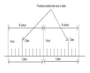
The TDMA frame with movable boundaries and pause detection offers an efficient method o integrating voice and data. The first region is used for voice with the mentioning that voice has priority.

Examples of data services introduced on top of existing voice services
i) CDPD introduced at the beginning of the 90es used available frequencies from FDMA system.
ii) GPRS introduced in the late 90es uses free timeslots from TDMA frame in GSM network
There have been done a lot of analyses in this matter. Most of the approaches took into consideration protocols that implied the synchronization between the transmitter and the receiver. The synchronous systems offer a good control over the delays, the required control in case of voice services. Unfortunately they offer weak flexibility in case of burst traffic that is specific to data transfer. Another approach that doesnt imply synchronization between the transmitter and receiver is the asynchronous one. In this case the mechanism of avoiding delays becomes more complex.
The design of a communication system is an essential task in designing a successful one. Unfortunately this task doesnt always have the required attention so mistakes in the hardware or software dimensioning happe.
References
[1] Delores
M. Etter, Engineering Problem solving with Matlab, Pretince Hall,
Intel Technology Journal, Scalable OFDMA Physical Layer in IEEE 802.16 WirelessMAN, August 20, 2004, https://developer.intel.com/technology/itj/index.html
Alcatel document, WiMAX Bearers and Bearer Seletion, Peak Throughput computation
Bechtel Invited Paper, PHY/MAC Cross-Layer Issues in Mobile WiMAX, Jan 2006
Harry R. Anderson, Traffic and application mix models, 8 May 2003, Print ISBN: 9780470844380 Online ISBN: 9780470861295
S. Alamouti, A simple transmit diversity technique for wireless communications, IEEE Journal on Selected Areas in Communications, Oct 1998
IEEE. Standard 802.16-2005, Part 16 : Air interface for fixed and mobile broadband wireless access sstems, Dec 2005
IEEE. Standard 802.16-2004. Part 16 Air interface for fixed broadband wireless access sstems, June 2004
Tero Ojanpera, Ramjee Prasad, Wideband CDMA for Third Generation of Mobile Communications, Archtec House, Boston, London
[10] Kaveh Pahlavan, Prashant Krishamurthy, Principles of Wireless Networks, Pretince Hall
[11] Using Matlab Graphics, Version 6
[12] Theodore S. Rappaport, Wireless Communications Principles and Practice, Pretince Hall PTR, Upper Saddle River, New Jersey 07458
|
Politica de confidentialitate | Termeni si conditii de utilizare |

Vizualizari: 1473
Importanta: ![]()
Termeni si conditii de utilizare | Contact
© SCRIGROUP 2025 . All rights reserved