| CATEGORII DOCUMENTE |
| Bulgara | Ceha slovaca | Croata | Engleza | Estona | Finlandeza | Franceza |
| Germana | Italiana | Letona | Lituaniana | Maghiara | Olandeza | Poloneza |
| Sarba | Slovena | Spaniola | Suedeza | Turca | Ucraineana |
1. Introduction
An electrocardiogram (ECG), also called an EKG, is a graphic tracing of the voltage generated by the cardiac or heart muscle during a heartbeat. It provides very accurate evaluation of the performance of the heart.
The heart generates an electrochemical impulse that spreads out in the heart in such a fashion as to cause the cells to contract and relax in a timely order and, thus, give the heart a pumping characteristic. This sequence is initiated by a group of nerve cells called the sinoatrial (SA) node, resulting in a polarization and depolarization of the cells of the heart. Because this action is electrical in nature and the body is conductive with its fluid content, this electrochemical action can be measured at the surface of the body.
An actual voltage potential of approximately 1 mV develops between various body points. This can be measured by placing electrode contacts on the body. The four extremities and the chest wall have become standard sites for applying the electrodes. Standardizing electrocardiograms makes it possible to compare them as taken from person to person and from time to time from the same person. The normal electrocardiogram shows typical upward and downward deflections that reflect the alternate contraction of the atria (the two upper chambers) and of the ventricles (the two lower chambers) of the heart.
The right atrium receives deoxygenated blood from the body and transfers it into the right ventricle, from where it is pumped into the lungs, to release carbon dioxide and be replenished with oxygen. The oxygenated blood feeds into the left atrium and is transferred into the left ventricle from where it is forced into the aorta and the rest of the body.
The heart muscle is made to contract and therefore pump blood around the body by means of an autonomous electrical signal that is generated by a bundle of specialized muscle fibres called the sinoatrial (SA) node. This node is located in the upper region of the right atrium. Within the node, changes in ionic concentration across the cell membranes cause a propagation of electrical activity to occur. The potentials build up to form an activation wavefront which manifests itself as a P wave, the first segment of an ECG signal, when it encounters the wall of the atrial muscle. This impulse proceeds through the atrio-ventricular (AV) node and a bundle of nerves around the ventricular region called the His-Purkinje system. There is a short period of isoelectric activity following the P wave after which the muscles of the ventricles are excited, causing a large deflection of the heart and a
Spiked waveform in three segments. The initial downward deflection is the Q wave, the large upward deflection is called the R wave and the final downward deflection is called the S wave. This section is usually referred to as the QRS complex. Following this complex is another relatively short isoelectric segment followed by the T wave, when re-polarization occurs and the ventricles return to their resting state. There is also another wave which may occur in some individuals as part of the re-polarization process, called the U wave.;
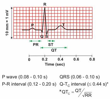
Figure 1. A typical single cardiac cycle waveform of a normal heartbeat
It is possible to non-invasively record the electrical activity of the heart by placing electrodes atspecific points on the body. This was first proven by Einthoven around 1900. Three mainmethods have now been established for recording ECG signals from patients. One uses a 12 leadsystem where electrodes are placed around the heart. The second is known as a 3 lead system, where three electrodes are placed on the torso in the following orientation; one near the right arm (RA), just below the right clavicle, one near the left arm (LA) one just below the left clavicle and one above theleft leg (LL), above the hip. There is also another reference electrode placed above the right hip, called the indifferent electrode. This arrangement is known as the Einthoven triangle. The measurement across the RA and LA is referred to as Lead I. The RA and LL measurement position is referred to as Lead II and the LA and LL measurement position is referred to as Lead III. The method used for monitoring long term or ambulatory patients is by either a one or two lead system. This is usually sufficient for monitoring life threatening disruptions to the ECG. In this work, the system under development currently monitors only one lead at a time.
Electrode design commonly consists of a silver conductor which connects to the body. An electrolyte of Silver chloride forms the electrical interface between the metal electrode and the skin. The central gel area of the electrode is coated with adhesive to enable the electrode to be fixed to the skin.
2. Functionality
In competitive cycling where every advantage can help you save a second or two and where the only part that can fail is the human body knowledge is power, to know the state of the cyclist in every moment of the race and to determine where to push and when to relax can make the difference between coming last and wining.
The project will be split in 3 parts:
Sensors: both hands and foot with a single lead and a pulse Ox for measuring oxygen intake
Transmitter a Bluetooth transmitter for real time data transitions
Ekg machine
The device has to be simple and light in order to be effective in a competition. The placement of the sensors will be on the wrists in the glove lining and on the right ankle, the oxygen saturation sensor will be placed on the index finger in the glove.
All the electronics will be placed inside the back of the helmet because that is the only available space where it will not inconvenience he raider and the aerodynamically flow.
The oxygen saturation sensor that will be placed on the finger is only composed of a led and a light intensity sensor that will feed row data to the transmitter, the analysis is performed as for the ekg at the receiving part with the help of a laptop in the follow car.

Microcontroller
3. Block scheme
4. Circuit scheme
Proposed Circuit
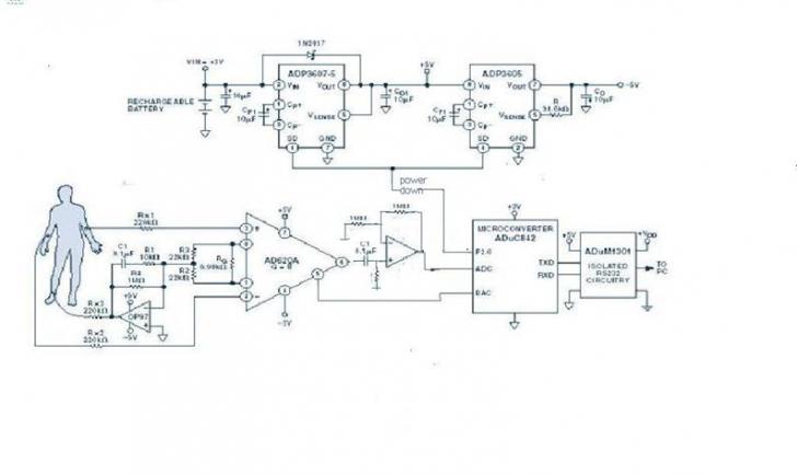
The signal chain can be simplified by using an ADuC842 Micro Converter, which allows the ADC, filters, and microprocessor to be combined in a single integrated circuit. Additional advantages are flexibility of filter implementation and isolation in the digital domain. The proposed system design is shown in Figure 2.
Figure 2. Proposed ECG configuration.
Analog Input Processing
The analog front end uses the typical approach with an instrumentation amplifier (IA) and a right leg common-mode feedback op amp. The IA is the AD620, a low cost, high accuracy instrumentation amplifier, with excellent dc performance : CMR(Comode Mode Rejection)>>100 dB to nearly 1 kHz, 50μV max offset voltage, low input bias current (1 nA max), and low input voltage noise (0.28 μV from 0.1 Hz to 10 Hz).
Signal Processing
The ADuC842 MicroConverter is well suited for the main signal processing tasks. It features a fast, 12-bit ADC and other high-performance analog peripherals, a fast 8052 microprocessor core, integrated 62KB flash memory for code, and several other useful peripherals, as shown in Figure 4.
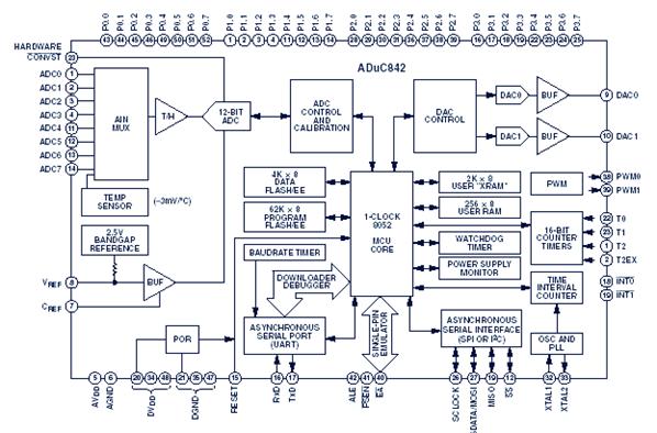
Figure 3. ADuC842 MicorConverter block diagram.
 The key
components of the MicroConverter for this design are the ADC and the 8052 core.
The ADC converts the analog output of the instrumentation amplifier to a
digital signal. The software written for the 8052 core processes the digitized
signal to produce the data for the ultimate ECG trace. As in many
MicroConverter designs, the software includes both complex high level code
written in C and time sensitive routines written in assembly code. In this
case, the implementation of band-pass filters and notch filters is in C, while
the ADC is controlled by assembly code. Assembly code, combined with converter
speed, enables the accumulation of multiple samples, enhancing the effective
resolution of the ADC well beyond its normal 12 bits.
The key
components of the MicroConverter for this design are the ADC and the 8052 core.
The ADC converts the analog output of the instrumentation amplifier to a
digital signal. The software written for the 8052 core processes the digitized
signal to produce the data for the ultimate ECG trace. As in many
MicroConverter designs, the software includes both complex high level code
written in C and time sensitive routines written in assembly code. In this
case, the implementation of band-pass filters and notch filters is in C, while
the ADC is controlled by assembly code. Assembly code, combined with converter
speed, enables the accumulation of multiple samples, enhancing the effective
resolution of the ADC well beyond its normal 12 bits.
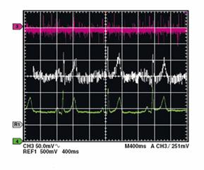
Figure 4 gives a good indication of the effectiveness of the MicroConverter. The top trace is the signal from the instrumentation amplifier applied to the ADC. The middle trace shows the initial results achieved using the C-code filtering only, while the bottom trace shows the final result after the processing of multiple conversions.
Filtering in C
The signal acquired by the instrumental amplifier is processed inside the MicroConverter through digital filtering. So, there are 2 digital filters of order 2 with infinite impulse response and sample frequency 500Hz. A filer is used to eliminate the perturbations at 50Hz. The cutting frequency is 10Hz and the band pass is of 10Hz also. The filters transfer function is the following:
![]()
The transfer function can be converted in an recursive algorithm:
NOutk=NInk-1.618NInk-1+NInk-2+1.5164NOutk-1-0.8783NOutk-2
We can scale the coefficients without altering the data:
iNOut = (4096L*iNIn-6627L*iNIn1+4096L*iNIn2+6211L*iNOut1-3598L*iNOut2)/4096;
The second filter is of Butterworth type, band pass filter, having the passing band between 0.05Hz and 100Hz.
The transfer function and the algorithm are as follows:
![]()
BOutk=0.4206BInk-0.4206BInk-2+1.1582BOutk-1-0.1582BOutk-2.
Implemented in C, this becomes :
iBOut = (1723L*iBIn-1723L*iBIn2+4745L*iBOut1-650L*iBOut2) /4096
The output can be easily scaled by changing the coefficients at the input. For efficiency, if both signals are positive, the division by 4096 can be done in the end by shifting to the right with 12.Bellow it is implemented a series of 5 low pass filers and 2 band pass filters cascade-connected.
while(1)
CONCLUSIONS
The helmet embedded EKG and pulse ox is both a practical and useful device, appealing mainly to the high performance racing. It combines the benefits of a medicine and science to help the human body to achieve better results without the use of steroids and to monitor both performance and health during a race because it is known that during high stress the human heart can fail leading to the death of the athlete which could be avoided.
|
Politica de confidentialitate | Termeni si conditii de utilizare |

Vizualizari: 3765
Importanta: ![]()
Termeni si conditii de utilizare | Contact
© SCRIGROUP 2026 . All rights reserved