| CATEGORII DOCUMENTE |
| Bulgara | Ceha slovaca | Croata | Engleza | Estona | Finlandeza | Franceza |
| Germana | Italiana | Letona | Lituaniana | Maghiara | Olandeza | Poloneza |
| Sarba | Slovena | Spaniola | Suedeza | Turca | Ucraineana |
Sellers scope of supply
The modernization consists of mounting the Control command and monitoring system for the manual and/or radio remote control of diesel-hydraulic locomotives LDH 1250.
The control and command system is divided in the locomotive 'machine-technical' part (MT) and the 'radio-technical' part (FT).
Technical specification of the locomotive radio-technical part (FT):
The FT part includes the transmitter (mobile man-pack) and the receiver onboard the locomotive with its interface to the MT part of the locomotive control and command system.
The interface between the FT and MT parts in this offer is specified as the standard interface. The description of the system is attached to this offer.
Technical specification of the locomotive machine-technical part (MT):
This part includes the locomotive control system with all its command-, control- and monitoring functions, which are required for the proper execution of all radio remote commands in remote control mode and the drive functions in the control mode from the locomotive control desks.
The modernized locomotive shall include the following new or modernized equipment:
|
No |
Denomination |
Description and technical characteristics |
Remarks |
|
Radio remote control system: |
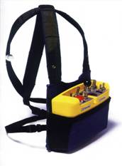
- The radio transmitter is ergonomic, light weight and carried in a supporting gear to be fitted on the operator. - The control system doesnt allow to transmit wrong and unwanted orders - See Ch.2.1 Appendix II for detailed description. | ||
|
Radio transmitter |
|||
|
Radio receiver |
|||
|
Antenna |
|||
|
Supporting gear (cover) |
|||
|
Batteries for radio transmitter and battery charger |
|||
|
Microprocessor control: |
- Performs controls, interlockings, protection and diagnosis both at local and at radio remote control - See Ch.2.2 Appendix II and Appendix IX for detailed description. | ||
|
Control system |
|||
|
Wheel slip control system |
|||
|
Control desks equipment |
|||
|
Pulse generator |
|||
|
Manual/radio mode switch-over unit |
|||
|
Data acquisition and processing system |
Diagnosis system to back up the operation- and maintenance activities in the depot | ||
|
Control- and protection equipment for locomotive brake adapting to remote control |
Electropneumatic elements that replace / complete the present pneumatic elements |
According to the braking diagram elaborated by Integral Consulting R&D |
|
|
Control equipment for diesel engine 6LDA28 type |
For adapting controls to diesel engine. |
||
|
Modified and adapted installation and equipment to match the following newly fitted equipment: Pneumatic installation; Electrical installation (equipment and wiring); Drivers desks; Electric cabinet |
The modifications are referring to the compliance with the requirements in the Offer. |
||
|
Fuel consumption recording system |
A specialized system is provided, alongside the sensors necessary to measure and record the fuel consumption. The system will be validated with the Romanian Railway Authority AFER. |
See item 3.2. - Description of new or modernized installations/ functions/ services, pos. 9 |
|
|
Automatic shunting coupler |
The automatic coupler is provided with a locking device which can be horizontally swung into the drawhook of the car to be coupled, and which latches in position only when completely coupled. The automatic coupler gets into the drawhook without any manual intervention, provided the respective hook is in the coupling area. The electric system, the air system and the software shall be modified accordingly so as to allow for the automatic control of the couplers, either from the locomotive, or remote. |
See item 3.2. - Description of new or modernized installations/ functions/ services, pos. 10 |
The control system and the radio system are dimensioned for continuous operation, free of wear, in principle.
The remaining pneumatic and monitoring equipment items are proven robust and reliable ones which in case of need should be ordered from the original manufacturers.
The supplier guarantees for all the equipment fitted as well as for all the works performed on the locomotive. The locomotive proper operation after its refurbishment shall be proved through the tests and checks carried out and shall be agreed on through the Acceptance and Validation Minutes, respectively.
The supplier shall give the end user advice referring to the spare parts to be ordered, and shall supply any necessary spare part, being liable for the software checks / adaptations required to ensure compatibility with the locomotives delivered in the previous batch.
As to the possible parts which are no longer delivered by various suppliers, the supplier shall provide compatible and feasible parts and solutions, respectively.
The remote control equipment shall be supplied by CATTRON-THEIMEG Company, the worldwide leader in the field.
|
No |
Denomination |
Supplier |
Remarks |
|
Radio remote control system |
CATTRON - THEIMEG | ||
|
Microprocessor control |
INTEGRAL CONSULTING R&D | ||
|
Air equipment |
KNORR BREMSE | ||
|
Control equipment for diesel engine 6LDA28 type |
INTEGRAL CONSULTING R&D | ||
|
Locomotive modernized and tested as per the Offer |
INTEGRAL CONSULTING R&D |
The required equipment shall be decided on and configured by INTEGRAL CONSULTING R&D, which shall be liable for its proper operation.
Radio controls for engines have been used successfully for more than 30 years. The first Theimeg radio control for an engine was used in 1972 in the former Krupp steel works in Rheinhausen.
Since then the radio controls from CATTRON- THEIMEG have been further enhanced with each device generation and today offer the highest level of safety and features.
The almost 30 years of experience and the delivery of several thousand radio controls have made THEIMEG the worldwide leading manufacturer of engine radio controls which exclusively applies the latest technology and the highest level of quality.
The TH-EC/LO radio control system, thanks to its high level of system safety and its extensive range of functions is suitable for all railway applications, particularly for industrial ones and in steel plants.
No other radio control combines safety and reliability with such a high level of user-friendliness and extensive operating functions as in the TH-EC/LO and thus fulfils even the highest demands in the radio control of traction vehicles.
The radio control system TH-EC/LO is the worlds first radio control system that has been deliberately designed in accordance with the latest existing safety regulations and safety regulations that are likely to be introduced. As a result of compliance with these stringent safety requirements, but also due to the extensive range of functions and the universal interface, the TH EC/LO can be used for almost all types of shunting locomotives and traction vehicles.
The overall system consists of a transmitter, a receiver and various accessories and fulfils all the requirements of railway applications, particularly industrial ones and in steel plants.
In addition to the extensive number of standards and guidelines which where already taken into consideration in the development of the TH-EC/LO, the overall system is also suitable for applications which require the safety level AK6 in accordance with DIN 19250. This is achieved through the use of duplicated processing electronics and positively driven safety relays whose output is permanently monitored by the receiver in the TH-EC/LO.
It is the only operation system worldwide in full compliance with all the operation safety provisions in the latest European standards specially elaborated for this field.
In addition the TH EC/LO conforms with numerous national and international standards which are listed below:
|
A sample of references by the national and class I railroads: |
|||
|
DB AG DSB FS NS NSB OBB |
|
RENFE SBB SJ SNCB SNCF Tranz Rail |
|
The transmitter has been designed on the basis of a strictly modular concept. It consists of the switching elements and controls, a processor unit for processing the commands and also a high-frequency HF module.
The processor unit consists of two separate processor systems in which the commands are processed independently of each other. Both processor systems must have reached the same result before the commands are transmitted to the receiver in the form of a telegram.
This redundant design and redundant command processing in the transmitter ensure that an individual defective electronic component cannot result in an incorrect telegram being generated. This arrangement means that the transmitter is protected against the failure of individual electronic components and can thus be described as self failure safe. Redundant design is used for wiring the controls to the transmitter electronic inputs.
|
|
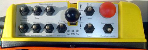
The ergonomic design of the transmitter and the standard optimized arrangement of the controls always guarantee reliable and safe single-hand operation. In addition, only tried-and-tested as well as reliable components with a maximum service life are used. The throttle for brake- and engine speed control is an easy-to-handle compass card switch. The throttle corresponds to the traditional method of operating THEIMEG radio controls and can be deflected in several positions. Each position is assigned to a specific throttle/brake command so that depending on the position of the throttle the commands speed increase/ decrease, brake application/ release can be set. |
The standard transmitter is supplied in a portable and impact-resistant design, and complies with ingress protection IP 65. Because the transmitter is not very heavy (approx. 2 kg), it can be carried for many hours without resulting in operator fatigue.
The swivel throttle corresponds to the traditional method of operating THEIMEG radio controls and can be deflected forwards and backwards in several positions. Each position is assigned to a specific throttle/brake command so that depending on the position of the swivel throttle the commands open throttle, constant throttle, close throttle, release brake, constant brake and apply brake can be set.
All controls such as switches, buttons, brake switch etc. are arranged on a scratch-resistant and weather-resistant alu-eloxal front panel.
For warning and status messages, the transmitter has a particularly loud buzzer and three LEDs arranged in line. The buzzer sounds for example when incorrect operation is detected, when the battery voltage is too low, when a defective component is detected or when another exceptional situation arises.
The LEDs serve to display the battery voltage, a system fault and normal transmission mode.
Mechanical damage to the transmitter antenna is a frequent cause of low ranges and thus reduces the availability of the remote control system. Accordingly, the transmitter antenna of the TH-EC/LO is accommodated inside the housing in order to provide protection against mechanical damage. All electronic modules are also housed in HF-resistant housings and are thus protected against the influence of electromagnetic interference.
After it has been switched on, the transmitter carries out a self test, and checks that the controls and internal electronics are functioning correctly. If this test is not successful, the transmitter automatically switches off and generates a sound warning signal.
As soon as the self-test has been successfully completed, the transmitter checks whether all controls are in zero position. The first command to be carried out from the portable unit (transmitter) is the locomotive brake command. After the radio receiver carries out this command on the locomotive, the transmitter is sent the confirmation which unblocks the radio transmission system.
The arrangement and the functioning of the individual controls on the transmitter meet the needs of the operator and the vehicle.
The control elements are agreed upon between INTEGRAL CONSULTING R&D and CATTRON TREIMEG in keeping with the specific characteristics of this locomotive and with the European standards (EN) regulations. The labels containing the control elements functions are in Romanian
As operation of a remote control always requires the operator to be in an upright position, the transmitter has a sensor which monitors whether the transmitter and thus also the operator are in an upright position.
If the transmitter or the operator are no longer in an upright position, a warning signal is generated after a brief period; this indicates that the transmitter is tilted. If the transmitter is not returned to an upright position in this case, the vehicle is automatically brought to a standstill by means of forced braking.
This can, for example, be the case when coupling and decoupling the wagons, when the operator has to work for a short period with an angled posture. When the button is actuated, the tilt monitoring facility is deactivated for a period that can be configured; at the same time the commands open throttle and release brake are deactivated.
In addition to this safety function, an additional operator monitoring facility (known as the vigilance function) can also be activated in the transmitter software. This is similar to the safety circuit installed on the locomotive (dead man).
This vigilance function specifies that operator actions have to be carried out on the transmitter at specific intervals of time (approx. 7 seconds). If such actions are not carried out, it has to be assumed that the operator is no longer controlling the vehicle with the necessary attention. In this case, the vehicle is brought to a standstill by means of immediate rapid braking (similar to the situation with tilt monitoring).
In addition to the commands issued by the operator the transmitter also sends an identification number (address) and a check code (CRC) to the receiver with each radio telegram.
The transmitter code (16 bits) is only used once throughout the world for each sender and indicates to the receiver from which transmitter the radio signal was received. The check sum is redetermined for each telegram and is calculated in accordance with a protected mathematical process for each command.
These numbers the transmitter code and the check sum are checked by the receiver for each radio signal received so that neither foreign nor falsified radio signals can be accepted.
The remaining probability with which a false radio signal is nonetheless processed with this procedure and issued to the engine is according to the Technical Inspection Association for Rheinland only once in every 3 million years for a duration of 100 ms.
In addition to this high level of protection of the radio signal the radio control can be equipped with several frequencies which, for example, can be set via a selection switch on the transmitter.
This allows, for example, switching from one radio signal with external interference to a second frequency without interference, thus significantly increasing the availability of the radio control in some areas.
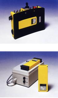
In the same way as the transmitter, the receiver also features strictly modular design. The receiver system consists of an HF receiver part, a processor unit and several modules for generating commands.
The processor unit also features completely redundant design, which means that the telegrams received are processed by both processor units independently of each other. If the two processor units do not reach the same output result, it must be assumed that one of the two processor units is no longer functioning correctly as a result of a defective electronic component. In this case, the vehicle is brought to a standstill by means of emergency positive action braking, and the identified error is displayed on the receiver display. This ensures that an individual defective electronic component can never result in an incorrect command being generated.
The receiver can be provided in various forms to suit the customers specific requirements. The standard receiver is housed in a stable cast aluminium housing equipped with a HAN 50 or HAN 64 connector.
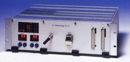
Throughout the entire operating period, the command generation procedure is displayed on an LED panel on the receiver. Status and error messages are displayed on a 7-segment display which informs the user of the current operating-state of the receiver and about possible faults.
Fault and system information can be retrieved. There is also the facility for modifying the configuration parameters directly on the vehicle without the receiver having to be dismantled or reprogrammed.
For generating commands, the receiver has max. 60 output relays of which 2 safety relays are reserved for the Emergency Stop command, 2 safety relays are reserved for the Passive Emergency Stop command and 56 relays are reserved for generating the other commands.
Positively driven safety relays can also be used for other safety-relevant functions such as open throttle, release brake which drastically improves the safety of the entire system.
A total of 24 safety relays can be used for additional safety-relevant commands; these can all permanently monitored.
Hardly any other radio control offers such a high level of safety with which incorrect generation of a command is next to impossible and where a defective relay is immediately detected by the system.
With this technique there is no possibility of incorrect behavior of the engine as a result of defective relays.
In addition to receiving and generating individual commands, the receiver is also extensively adapted to meet the specific needs of the vehicle and the user. A range of system parameters is available for this purpose which can be set using a programming device.
These parameters are used to set the radio control to the vehicle type, the selected commands and functions, the desired safety characteristics and so on and so on.
Some parameters can also be set directly on the vehicle for fine tuning of the system.
Receiver programming is a further facility for adapting the system to meet the specific requirements of the particular engine. For this purpose, a programmable controller program is stored in the receiver; this processes the commands that are received before they are transmitted to the vehicle.
Links such as automatic application of the
brake when changing the direction of travel or refusal of a change in the
direction of travel at speed >0 can be set with the aid of the program.
It is also possible for the system to be programmed to generate a warning
signal when the remote control is activated or for the brakes to be
automatically released for a hill start.
The assignment of the individual commands to the output relays is also completely free, whereby the commands can either be output to an individual relay or to several relays.
Thus the functions desired by the user and the command output can be freely set on the receiver such that the TH-EC/LO radio control can be adapted to virtually all the needs of the vehicle and the operator.
When the system is switched on, the receiver first carries out a self test, and checks to ensure that the hardware and software are functioning correctly. This test is carried out in various stages, and these stages are displayed on the 7-segment displays of the receiver. The value 00 appears in the 7- segment display only when this test has been successfully completed. This is the way in which the receiver indicates that it is now ready to receive the first telegram of the transmitter.
Self tests are also carried out constantly during ongoing operations; these ensure that defective components are detected and that - if necessary - the vehicle is put into a secure condition.
In addition to self test, the receiver also has an automatic recording system which records all errors that are identified (similar to a black box in aircraft).
These errors include minor problems such as radio interference of brief duration which does not always result in positive action braking and deactivation of the radio control.
In addition to the transmitter and the receiver, the radio control TH-EC/LO also includes several accessories. These accessories are: a pouch made from particularly tear-resistant canvass material, a storage battery recharger, two rechargeable batteries and a vehicle antenna featuring lightning and high voltage protection.
|
|
The position of battery on the back side of the transmitter The battery recharger The recharger is equipped with a fully automatic recharging control facility in order to avoid the memory effect, and can be operated either with 24DC, 230AC or 110VAC. The rechargeable batteries are equipped with an integrated temperature monitoring facility for particularly gentle recharging and discharging. Every battery features quintuple gold contacts and a capacity sufficient for a complete 8-hour shift with 100 % ON time. |
For safety reasons, the transmitter and receiver use dual microprocessors. A fail-safe monitoring electronic compares all received telegrams for correctness and only sends these commands to the locomotive if both sets of electronics have the same processed result.
The entire system is suited for applications which require the risk class AK6 according to DIN v 19250 and the safety levels IL3 (EN 50128) and SIL3 (EN 501129).
All requirements of EN 50239, especially the safety relevant functions are fulfilled for all command possibilities.
The high level of development know-how and special knowledge of the CATTRON THEIMEG engineers with respect to the safety of remote controls for locomotives are recognized as a verified development organization for safety related applications.
Additional safety features
Throughout the world, more than 6,000 radio remote control systems for locomotives, more than 25,000 radio remote control systems for cranes and machinery, and more than 600 radio remote control systems and data communications systems for special applications speak for themselves.
Our high standard of quality is constantly being improved by continuous development of all CATTRON THEIMEG products. Our development processes are supported by the involvement of inter nationally acknowledged institutions such as universities, technical control boards, Lloyds Register and the German Federal Office for Railways.
Certification to ISO 9001:1994 and EN ISO 9001:1994, recognition as a qualified development company by the German Federal Office for Railways and the recognition of our Quality Management System by many European rail companies all testify to Theimegs high degree of reliability, skill and experience in industrial radio technology.
|
|
|
|
|
Multiple use of one Frequency: Modulation: Deviation: Channel Separation: Transmitted RF power: Receiver Sensitivity: Transmission Rate: Response time: Error detection: Telegram structure: Telegram Security: Address Coding: Operating Temperature: Protection Class: Transmitter weight: Receiver Dimensions Command output: Output interlocks: Operator monitor: Certifications: |
405-480 MHz MOD-MIX (Standard) and Vario (Option) FM (Frequency Modulation) approx. 2 kHz 20/25 kHz (12,5 kHz optional) 300 mW at 50 Ohm (standard) < 1 mVolt 4800 bit/sec. / RF transmission approx. 50 ms (typical) redundancy in hardware PPM, HDB3, VWC CRC (Cyclic Redundancy Check), d 16 bit -20 to +60C I P65 approx. 1.9 kg depending on model 19-Rack, 3 levels relay output (Standard) available for all locomotive types tilt sensor, vigilance EBA and PTT approval in almost all European and many overseas countries |
The radio remote control has an action range of approx. 1000 m. On exceeding the radio systems the engine power is switched off automatically and the brakes are applied (emergency stop).
The locomotive shunting driver controls the locomotive through the portable radio transmitter (command transmission of the radio receiver installed on the locomotive for converting, monitoring and executing the commands by the control system which commands the execution elements) The radio transmitter can be used by the locomotive shunting driver equally from the locomotive (driver's cab or other location on the locomotive) and from outside the locomotive up to a range of approx. 1000 m.
In the transmission range of the radio remote control system up to 5 locomotives can be operated in the same area. The controls provide the required safety and selectivity.
The SIDEX locomotives converted to radio remote control operation can be operated either in manual control mode, or alternatively by a portable radio transmitter. (Switching over from manual to radio remote control operation is performed) by a key operated switch over unit to be installed in the driver's cab.
During radio operation additional safety monitoring will bring the locomotive to standstill in case of a safety fault (Emergency stop).
The control- command- and monitoring system to be fitted on the locomotive is in strict compliance with the safety standards for railways and with the technology principles approved of.
EN 50155 11/95 Electronic equipment for railway applications used on rolling stock.
EN 50121-3-2:2003 Railway applications. Electromagnetic compatibility. Part 3-2. Rolling stock. Instrumentation.
The microprocessor- provided control system is based on modular standard units for hardware as well as on development- production- and application software. The user software is individually adapted by programming and defining the relevant parameters according to the specific requirements.
The control systems find broad application within challenging fields of operation, including radio remote and multiple unit control, for all railway applications, particularly for industrial ones and for those in steel plants.
The system is connected to the locomotive peripheral equipment via input/output digital and analogue modules.
Storage temperature range: -40 to +85 C
Operation temperature range: -25 to +70 C
Relative humidity: 75% mean over a year, 90% 30 days a year
Rated supply voltage (Un): 24VDC (0,7 Un to 1,25 Un)
The control system consists of:
central unit (Master and Slave)
input/ output modules
speed transducers
local control elements
radio/ manual switching unit
The unit is equipped with printed circuit modules for locomotive control, monitoring and protecting during running and braking, at improved adhesion , in radio remote and manual mode for carrying out the following the functions:
control and command of the locomotive in manual operation mode
control and command of the locomotive radio remote (Cattron - Theimeg) operation mode
release of operation after check for correct initial conditions in either operation mode
acceptance of radio remote commands from the receiver and checking them for possible contradictions
control and monitoring of the direction of travel and standstill
control of the diesel engine starting, with radio remote control
control and monitoring of the diesel engine including lube oil pressure, cooling water level and temperature and engine speed control.
control and monitoring of the pneumatic brake system including the pressures in the brake pipe and in the brake cylinder
self diagnosis
In the control- and protection system the following locomotive control functions have been integrated
The following protections will automatically bring about engine and locomotive stop:
Insufficient engine lube oil pressure
The following protections will automatically bring about engine idle running and warning in the drivers cab:
Locomotive overspeed
Engine cooling water excessive temperature
The wheel slip/ wheel skid control system is integrated through the application software to control and optimise the traction and brake power of the locomotive, and has the following functions:
Automatic starting traction effort limitation and automatic braking effort control.
Wheel skid / wheel slip control
Automatic, travel direction- dependent sanding signals (switchable)
Self diagnosis.
In order to detect and monitor the wheel slip/ wheel skid, locomotive standstill and the direction of travel, a pulse generator is provided on one of the axles.
For locomotive manual control from the drivers cab there are used two ergonomic and optimized controllers (one for each).
These controllers together with the new electrica land pneumatic equipment (to be fitted in the small hood) will replace the former drivers desk locomotive control equipment (controllers, reverser, locomotive brake cock (FD1 type), train brake cock (KD2 type) and shall be integrated into the control desk, ergonomically as well as in point of design.
The switch over unit has two key-operated switches, and will be integrated ergonomically as well as in point of its design into the control cabinet.
The systems operate basically on the master-slave principle.
The master computer controls all other intermediate computer printed circuit modules via a serial interface.
The master computer contains the user specific program manages all parameters and current data, and stores any malfunction or faults.
Faults will be stored even if the power supply to the systems is switched off.
The other active extension modules from the computer each has a separate microcontroller with the specific program for the particular type of. module, so that all equivalent types of printed circuit modules are interchangeable.
The program parameters are transferred to the individual peripheral units, when the master computer is switched on.
The address of each extension module is determined only as a function of the slot in H/L coding, which results in the flexible use of identical types of p.c. modules within the system.
The functions and logic operations of the equipment are defined by the programming of the master computer.
The specific functions and interlockings of the locomotive control and command system are defined by the programming of the master and slave computers.
Communication among the system components is achieved through a CANOpen protocol.
The drive and brake commands are given by the corresponding control handles etc. from the transmitter in radio remote operation mode or from the control handles etc. at the Drivers Desk in manual operation mode.
In all cases the signals reach the control system through digital input p.c.modules and are checked according to the safety philosophy, before they are processed according to the user specific program.
Safety relevant signals such as 'Emergency stop' will be processed in parallel through a second path.
In addition the control system includes a monitoring of all important components and functions, which in case of critical or operational dangerous situations automatically puts the locomotive in 'the safe condition', i.e. in this project an emergency standstill.
Wheel motions are detected via a digital pulse generator, by means of sensing the movement of the teeth of a gear wheel ( see below concerning its construction, delivery and mounting ), rigidly mounted at the end of one of the axles and are read directly into the computer as an electrical signal.
The system is activated during traction only (diesel speed > idle, travel direction is chosen and transmission is coupled).
In case of wheel slip, after the slipping has been stopped, the automatic sanding control program will start, to improve the coefficient of adhesion in order to prevent further wheel slip, and to allow for higher tractive efforts.
Wheel skid is likewise detected by monitoring the wheel motions through the information provided by the pulse transducer.
The system is active during locomotive braking only.
Initiation of the wheel skid protection and control of braking performance is effected via suitable anti-wheel skid solenoid valves, installed on the brake pipe line near to the brake cylinders, for controlling the optimum braking forces and stopping distances by quickly adapting the pneumatic brake cylinder pressure.
Also here the automatic sanding control program will be active after wheel skid to improve the prevailing coefficient of adhesion achieve the minimum braking distance.
If wheel skid is not eliminated within a preset time interval, then the wheel skid control system is automatically put out of operation in order to provide locomotive safe running.
To reduce the risk of wheel slip, due to the application of excessive tractive effort at start, and to automatically utilize the available adhesion to its optimum over the entire speed range, and so achieve an overall improvement of the tractive performance of the locomotives, active countermeasures have to be automatically taken.
The tractive effort limitation manages the forces within the designed values according to a preprogrammed speed versus the fraction force curve.
The computerized systems are equipped with self-testing functions, which can diagnose a fault and detect whether the peripheral equipment on line is correctly connected and functioning properly.
The control- and protection system operates automatically for each fault, and at the same time, the fault is stored and there are given commands referring to the protection measures.
The locomotive pneumatic system includes all the pneumatic and electropneumatic equipment and apparatuses jointly operating to:
The system diagram shall be organized, from a functional point of view, into the following groups of apparatuses:
The main modifications as to the already existing system on the locomotive, made within the modernization works on the locomotive, are the following:
The locomotive is equipped with the following braking system:
direct pneumatic brake
automatic pneumatic brake
parching brake (hand brake)
The main modifications as to the already existing system on the locomotive, made within the modernization works are the following:
Modification to the direct and
automatic brake control system by implementing the KNORR BREMSE brake
equipment into the already existing system.
The system allows for the train and locomotive braking. Braking is controlled
either remotely or from cab desk. The system takes over in totality the
functions of the self regulating control brake valve D2 existing on the
locomotive.
Direct brake is electropneumatically controlled by means of the Knorr-Bremse valve which will replace the existing pneumatic valve.
|
No |
Denomination |
Description and technical characteristics |
Weight (kg) |
Pcs./loco |
|
Control- and protection equipment for locomotive brake adapting to remote control |
Equipment decided on by Integral Consulting R&D, included into the supply and made by specialized manufacturers from E.U (as per the technical documentation) |
1 set |
Maximum system rated pressure 10 bars
Auxiliaries rated pressure 6 bars
Brake cylinder rated pressure
Automatic brake 3,8 bars
Direct brake 3,6 bars
The diesel engine speed radio control calls for the modification of the existing control system which is purely pneumatic.
The system proposed consists in replacing the diesel engine speed control valve existing at present in the master controller by a proportional electric valve. The radio or local control function is controlled by the locomotive computer according to the unified signal sent from the portable unit or from the control unit on the desks, as well as to the conditions and interlocking imposed by the application software.
This modernization means giving up the present master controllers in the cab.
2.5. Fuel consumption recording system
A specialized system is provided, alongside the necessary sensors in order to measure and record the fuel consumption.
The system shall allow for fuel consumption analysis in order to eliminate the causes leading to fuel waste and to optimize the consumption.
2.6. Automatic shunting coupler
The automatic shunting couplers allow for the automatic car coupling, being used mainly on the remote controlled locomotives.
The electric system, the air system and the software will be modified in order to allow for coupler automatic control, either from the locomotive, or remote.
|
Politica de confidentialitate | Termeni si conditii de utilizare |

Vizualizari: 1033
Importanta: ![]()
Termeni si conditii de utilizare | Contact
© SCRIGROUP 2025 . All rights reserved