1
System Summary
This chapter introduces the basic operations of
ES-2000+ Fingerprint Access Control System. The system Max fingerprint capacity
is 3000 , suitable for 1000 people enroll , each one could register 3
fingerprint.
1.1
Structure of
ES-2000+
n
ES2000+ system includinig :
n
Fingerprint Processor and Door Lock Controller
n
Door Lock Controller :
Lock control unit : ES-401 /
ES-402 / ES-403 / ES-404
Power unit : ES-501 / ES-511
Battery unit : ES-521
* ES2000+ B without Door Lock
Controller
1.1.1
Fingerprint
Processor
Fingerprint Processor (hereinafter refer to
as Processor) is the most important component of ES-2000+
fingerprint access control system. The
Processor is responsible for the standalone real-time fingerprint processing,
matching, enrolling and security controlling, fingerprint templates saving,
transaction logs saving, and the encrypted communication with PC host. It is
made up of several parts, such as LCD, keyboard, door bell button, fingerprint
sensor, reset key and al-alloy shell, as Diagram 1 is showed. 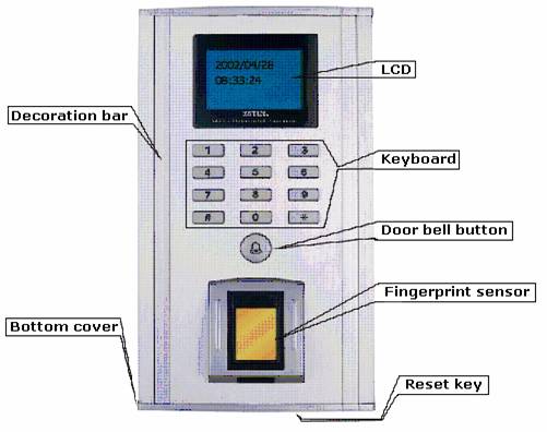
Diagram
1 Fingerprint
Processor
1.1.2 Door Lock Controller
Door lock controller (hereinafter refer to
as Controller) is one of
chief components of ES-2000+ fingerprint access control system. The new-style
controller consists of 3 parts: lock control unit, power unit and battery unit.
They can control various
electric door locks, execute the commands from the Processor, provide the whole
systems power and possess the interface of LAN-connection. The
controller is showed as Diagram 2 followed:
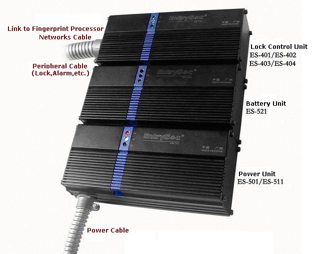
Diagram 2 Door Lock Controller
1.1.2.1
Lock Control
Unit
Lock control unit is the core of new controller. It
executes commands from Processor to control peripheral equipment such as door
lock and alarm.
1.1.2.2
Power Unit
Power unit is in charge of voltage transformation
and power supply, which is classed for Linear Power (ES-501) and Switching Power (ES-511)
Supplies. It neednt power unit if there is DC 12V power.
1.1.2.3
Battery Unit
Battery unit (ES-521)
provides UPS for ES-2000+, which can self-charge in normal power supply.
NOTICE:if
battery unit isnt linked to the Controller, please charge it for 15 hours in
every 3 months in order to protect the battery unit. If user need power supply
longer when power is cut, you may add more power unit.
1.2
Substantive
Explain
1.2.1
User Class
System
ES2000+ Fingerprint Access Control System have two
User Class:
l The first is refer to ES2000+ fignerprint equipment
User Class, There are three user classes
to perform the management function: Supervisor, Manager and User.
l The second User Class is refer
to PC tools / software user, they use the PC software to setup the docr control
data, index and management.
The supervisor has the highest
authorization. He can enroll, delete managers and users as well as revise
parameters (he can delete all users of all classes); manager can only enroll,
delete users.
The PC user do the fingerprint
system and equipment maintenance under the PC software, main in : Log
management, data and Index record , backup , maintenance and diaplasis.
(Note : PC user use the
software contact to Access Control System, should ensure the equipment in
vacant condition , otherwise do not make the communication with system.)
Vacant condition : Refer to
ES2000+ Fingerpint Access Control System when in no user situation, Processor
not enroll any user data or delete all the user data situation.
Ready condition : Refer to
system not receive any sign or in vacant condition, the LCD show the present
date and time.
Door condition : Refer to
door open and close situation. If user have installed the door condition
inspector ( such as Magnetic Lock ) and contact to access control system , then
the system will check the door condition from time to time.
Lock condition : Refer to
lock open and close situation. If user have instaled the lock condition
inspector ( normal most of electrical lock will enclose the working condition
inspector ) and contact to system , then the system can check the lock
condition in any time.
Go-off Switch : Refer to
one selected components of system , which install inside for user open the door
under permit.
Offline use : Refer to
system could enroll , save , enquiry , setup , authentification and so on
process without contact to PC internet , just contact electrical power apply.
A , C type proessor could control the lock directly , B
type need use the Wiegand controler to contro the lock.
Internet Assisstant Management : Refer to use contact the PC internet under the RS485/TCP, use the PC
software to control difference place doors , setup , backup, diaplasis data and
so on.
The following context will
mention the Internet Assisstant Management from time to time. If use need this
function please note the relative precessor setup , otherwise ignore it.
Alarm on Theft
Including Alarm on Prying, Alarm on Cable
Disconnection, Alarm on Illegal Door-Open and Alarm on Door-Open Overtime.
Alarm working method: when the
Controller raises alarm, it also outputs alarm signal to the control center at
the meantime to inform the security personnel.
Alarm on prying: alarm
generates automatically when the Processor is pried.
Alarm on disconnection: alarm
generates automatically when the communication cable between the Processor and the
Controller is damaged.
Alarm on illegal door-open: alarm
generates automatically when the door switch is pried.
Alarm on door-open overtime: alarm
generates automatically when the door opening duration exceeds the door-open
overtime setting.
1.2.2 Alarm on Threat
An alarm finger is to enable
the function of Alarm on Threat. For example, when a user is threatened to open
the door, to say, encounter a robber, he can adopt the alarm finger to open the
door. As a result, the door will be opened without warning and an alarm signal
will be sent out secretly to security department such as police at the same
time.
1.2.3
Fingerprint
Verification and Password Verification
System supports the verification methods of
fingerprint verification, password verification and the fingerprint +
password verification. Considering that the physical condition of some users
fingers may not be good enough to perform fingerprint enrollment and
verification, there may be some difficulty when performing these processes,
system adopts password verification as an alternative option. With the option
of Verification Priority, every user can set the priority to the fingerprint
verification or the password verification. When the fingerprint verification is
prior to password verification, system verifies the fingerprint verification
first and then applies password verification if the fingerprint verification
fails. When the password verification is prior to fingerprint verification,
system verifies the password verification first and then fingerprint
verification applies if the password verification fails.
1.2.4
Verification
Mode of 1:1, 1:N and 1:X
1:1 Verification Mode: firstly,
input User ID and then verify the relative fingerprint. System calls the
fingerprint template according to the User ID to perform the verification
process.
1:N Verification Mode: verify the
fingerprint directly without the User ID, and then system will search for the
matched fingerprint automatically.
1:X Verification Mode: firstly,
input the last several digits of User ID, for the user of User ID 6618, he may
input 8, 18 or 618 as he likes, and then verify the relative finger. The
verification speed increases with series when inputting more digits.
Speed priority: 1:1 > 1:X > 1:N
1.2.5
Language
Setting Function
System supports Simplify Chinese and English
interface, which can be easily switched in system setting.
1.2.6
User
Association
For the
purpose of enhancing system security, users may set User Association. When
setting the association relation among users not less than two persons, all
associated users must pass the verification of their fingers when processing
door open verification or entering the system management menu. User association
may be the association between/among fingerprint users, the association
between/among password users and the association between/among
fingerprint+password users.
1.2.7
Fingerprint
Association
For the purpose of enhancing the security level,
user may set finger association after enrolling more than one finger. Hence the
user must pass the verification of all associated fingers when processing door
open verification or entering the system management menu.
1.2.8
Communication
ES2000+ series products provide various
communication, such as RS485、TCP/IP、Weigand, users may choose freely according to local
conditions.
1.2.9
New-style
Controller
The new
controller consists of 3 parts: lock control unit, power unit and battery unit,
and more new functions of them are added:
It will
produce alarm ringing and send alarm signal to security center. System distinguishes
local alarms and remote alarms to enable users make different response
according sounds and signals.
Door and
switch status detecting makes system control function more efficient.
Door bell and
remote control switch are embedded in new controller, so users may open door
remotely and conveniently.
2
Installation
2.1 Preparation
Before installing the
Processor, please check and write down the Module Serial Number, Product Serial
Number and Device Number set at 0 (these three items have already written in
the unit). Add the new unit with the PC based management software and set the
device number, and then distribute the unit to administrators on PC for further
management. To remove this unit, delete it first then add it again following
the same steps mentioned above. The device number changes to 0 automatically
upon deleting.
2.2 Installation steps
2.2.1 Initialization of fingerprint processor
Be care not to scratch the surface of
Processor with screwdriver while installing Processor.
2.2.1.1
Initialization
on the wall
Before installing Processor, make the
walls surface clean and smooth.
At first, according to the dimensions of Processor (Diagram
3、4), drill
the fixing holes and cable hole (cable between Processor and Controller) in the
wall at the height of 1.4~1.5 meters.
If the walls surface isnt smooth enough to close the alarm
switch (alarm on prying) behind the Processor, choose the following two kinds
of fixing pad (Diagram 5、6).
Diagram 3 Dimensions
of Fingerprint Processor(mm)
NOTICE: hole 1~4 in the Processor are for mounting onto wall
using cup head self tapping screws ST330.
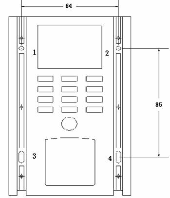
Diagram 4 Dimensions
of Fingerprint Processor(mm)
Diagram 5 Dimensions
of Fixing Pad (BJ) of Fingerprint Processor(mm)
NOTICE: hole 1~2 in the fixing pad (BJ) are for mounting
onto wall using pan head self tapping screws ST3.525.
Hole 1、2、3、4
in the fixing pad (BJ) are for fixing the Processor using
cup head self-taping screws M316.
Diagram 6 Dimensions
of Fixing Pad (GZ) of Fingerprint Processor(mm)
NOTICE: hole 1~2 in the fixing pad (GZ) are for mounting
onto wall using pan head self tapping screws ST3.525.
Hole 1、2、3、4 in the fixing pad (GZ) are for fixing the Processor using cup head self-taping screws M330.
2.2.1.2
Dismounting
bottom cover
Unscrewing the screws on the bottom shell and
dismounting the bottom cover as Diagram 7 followed:
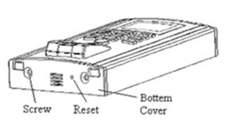
Diagram 7
2.2.1.3
Removing
decorative strips
Removing the decorative strips as Diagram 8
followed:
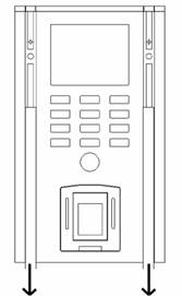
Diagram 8
2.2.1.4
Fastening
1、2、3、4 are fixing holes, details please see to Diagram 3
and 9 for mounting dimensions.
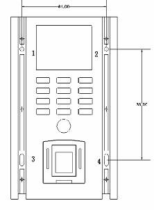
Diagram 9
2.2.1.5
Fitting back
decorative strips
Fitting back the decorative strips as Diagram 10
followed:
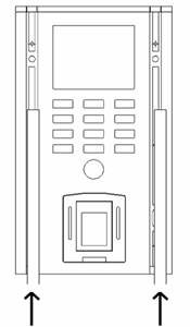
Diagram 10
2.2.1.6
Mounting
bottom cover
Mounting the bottom cover and screw the screws on
the bottom as Diagram 11 followed:
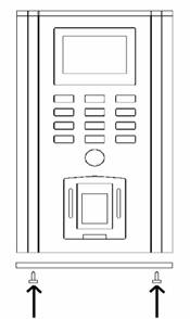
Diagram 11
2.2.2
Installation
of Door Lock Controller
Installing
the Controller at concealment, providing power (AC 220V) and connecting cables
in the Controller and ones between Processor and Controller, etc..
Following is three kinds of methods about
installing the Controller:
① Fixing outside
there are two brackets in every unit. One side of the bracket is fixing at the
two units and the other side is fixing onto wall or somewhere using cup head
self tapping screws M430. Dimensions of the Controller are showed as diagram
12.
② Fixing inside
there are two holes in every unit for fixing onto wall using cup head self
tapping screws M430. Dimensions of the Controller are showed as diagram 12.
③ Synthesis using
holes in the brackets and the units to fixing at the same time.
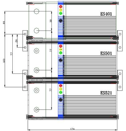
Diagram
12 Dimensions
of Door Lock Controller(mm)
2.3 Cable
2.3.1 Cable between Processor and Controller
The
cable is used for the connection between Processor and Controller. Users can buy standard net cable of various
lengths according to their needs (with 8P8C RJ45 at both ends). The cable is illustrated as
below Diagram 13:
Diagram 13 Cable
between Processor and Controller
2.3.2 Cable for Ethernet
Cable for Ethernet is used
for linking to HUB to communicate PC by TCP/IP, which is made according to the
standard (586A) of
Ethernet cable.
2.3.3 Cables in the Controller
Cables
in the Controller are used for power (DC 12V) connection among lock unit, power
unit and battery unit. The cables type is recommended to choose AWG #20 (GB5023-1997 227 IEC 16/0.2 copper, PVC). Connection
is showed as diagram 14.
2.3.4 Power Cable
Power
cable is used for connecting AC 220V into the power unit, which adopts the
international standard of power cable GB5023-1997.
2.3.5 Other Cables
When the lock control unit
connects with signal line (such as door or lock status line, line of switch
inside door, etc.), the cables type is recommended to choose AWG #22 (GB5023-1997 227 IEC 16/0.15 copper, PVC). When
connecting with power line (door or lock control line, etc.), choose AWG #20
(GB5023-1997 227 IEC 16/0.2 copper, PVC). Cables for RS485 net should be
chose the standard net cable.
2.4 Connection Schematic
2.4.1 Stand-Alone
The Connection Schematic
of the Controller is showed as diagram 14. The choice of cables type refer to
section 2.3. All kinds of locks and alarms are different in their function and
electric parameters, so choose correct cable type according to their electric
parameters.


A- / TXD
B+ / RXD
GND
Lock+
Lock power
|
|

Diagram 14 Connection
of Door Lock Controller A
NOTICE: JP1、JP2
closed (TCP/IP), open (RS485);
JP3
(lock type) 12 (NC), 23 (NO);
JP7
(alarm type) 12 (NC), 23 (NO).
The ports
of the same definition in same unit can be used for exchange, for example, port
3 and 4 in power
unit are all GND.
The
Connection Schematic of the Controller without the battery unit is showed as
diagram 15:
A- / TXD
B+ / RXD
GND
Lock+
Lock power
|
|
Diagram 15 Connection
of Door Lock Controller B
2.4.2
Indicator
Light
There are three indicator lights in the
Controller as following list.
|
|
Red Light
|
Yellow Light
|
Green Light
|
|
Power Unit
|
Fully loaded
|
DC power supply
|
AC power supply
|
|
Battery Unit
|
Battery provides power
|
Power unit provides
power and charge up battery
|
Power unit provides
power
|
|
Lock Control Unit
|
Alarm (except alarm on door-open overtime)
|
Light all the time and
twinkle while connecting with Processor
|
Unlock legally
|
2.4.3 Network
2.4.3.1
RS485 Network
ES-2000+A
can communicate PC in network by RS485 way through one RS232/RS485 convertor. It allows for 32 sets of ES-2000+A to work in
network and the maximum transmission distance is 1200 meters. A repeater is
needed when exceeding 32 sets of ES-2000+A. ES-2000A Processor should be equipped with ES-401 or
ES-402 Controller. In order to carry out the multiple devices network
management, firstly via ES-2000+ PC Management Software should be run in PC,
which is charge of management of system log, users data and system parameters.
Below (diagram 16) illustrates RS485 network connection:
Diagram
16 RS485 Network
NOTICE:
add one resistance (120Ω) at the begining and the end to keep system load
in balance as diagram 11 is showed.
2.4.3.2
TCP/IP Network
ES-2000+C can communicate PC in network
by TCP/IP way. It allows for 255 sets of ES-2000C at most to work in network. ES-2000+C Processor
should be equipped with ES-403 or ES-404 Controller. Its the same that ES-2000+
PC Management Software should be run in PC to manage the multiple devices.
Below (diagram 17) illustrates TCP/IP network connection:
Diagram 17 TCP/IP Network
2.4.3.3
Wiegand
Network
ES-2000+B communicates PC
in network by Wiegand, which equips with general door lock controller in
Wiegand. ES-2000+B is in charge of fingerprint enrolling and matching. If
verifying successfully, it will send matching resultID(Identification)
numberto door lock controller, which opens the door lock. Thus, ES-2000+B
takes place of IC card reader to combine with door lock controller. It makes
the whole system more safe and convenient. For all kinds of door lock
controllers are different in their structures and electric parameters, please
refer to their instruction manual for connection.
3
Operation
3.1 Guide
3.1.1 Notice for Fingerprint Extraction
When extracting fingerprint for enrolling or matching,
please place the finger on the sensor according to the correct methods;
otherwise it will capture unclear and part fingerprint so as to affect
fingerprint enrolling or matching.
The correct method is to place the finger at the center of
the sensor with respect to the enrolled position ( the vertical direction of
the sensor). Press a little hard on the sensor to ensure 3/4 of your finger
surface touch the sensor surface as followed Figure 18.
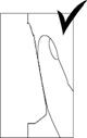
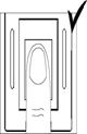
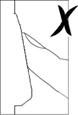
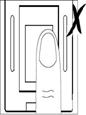
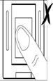
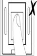
Figure 18a Figure 18b Figure 18c Figure 18d Figure 18e Figure 18f
NOTICE: It is correct methods
showed in Figure 18a、18b.
It
is not the correct methods showed in Figure 18c、18d、18e、18f.
3.1.2 Fingerprint Sensor
Be
care not to scratch or prick the fingerprint sensor, and please use tampon with
some water or alcohol to clean its surface timely.
3.1.3 FAQ and Solutions
If the system can not work properly, please refer
to section 4 or contact with our local agency or subsidiary at any moment, or
contact us.
3.2 Brand-New Default Configuration
FOR THIS
CONFIGURATION, THE DEVICE HAS NO FINGERPRINTS
Under this configuration,
upon powering up the Controller, the LCD will show the device number and then
Time/Date information. For example:
If any of the keypad
buttons except for the * Button is
activated under this configuration, the LCD will display No Users, please
contact supervisor. before going back to the main Time/date display.
There are two ways to add
the first user (supervisor):
1. Press *, then LCD displays
Please add the first supervisor. (operations see to Add
New User on Page 5 for more details);
2. Enroll users fingerprint or managers
fingerprint on PC then download it to ES-2000 unit. LCD displays Connecting
with PC while the device is trying to
establish a connection with PC. Regards to operating the ES-2000 on PC, please
refer to ES-2000+ user management in ES-2000+ Management Software
Operational Manual.
Notice:
the *
Button is confirmation; the # Button is
cancellation.
3.3 Door open verification
Users fingerprint data
must exist in the ES-2000+ when performing door open verification. There are
seven methods regarding this function: via one person one finger, one person
multiple fingers, multiple person one finger and multiple person multiple
finger; one person one password, multiple person one password; multiple person
finger or password. The match method for verification varies according to the
setting at the time of enrolling. User can do 1:1, 1:N or 1:X verification
directly via the processor. Verification times (1-3) can be adjusted through ES-2000+
Management Software (hereinafter refer to as ES-2000+ MS).
Its default value is once.
3.3.1 One to one (1:1) verification:
The Time/Date display is
as followed:
In the Time/Date display,
firstly input ID on the keypad and press * button to confirm the ID, then
place finger on the sensor with slight pressure (a micro-switch is depressed as
the finger presses on the sensor to wake the system. This will not be explained
again in the ensuing paragraphs). The LCD will display the following:

Then LCD displays:
Just follow the LCD
Display instructions for the entire verification process. E.g.: Place finger,
Remove finger, Move up, Move down, Move left, Move right.
Upon successful
verification, the LCD displays the following:

(User of ID XXXX access granted)
At the same time, System
will activate the door lock to open, write down the door-opening time and the
user ID to form the door-opening transaction. Then the display goes back to
Time/Date display and the door will be locked again automatically after several
seconds (this duration can be specified by the user in the System Parameter
Setting. Its default value is 5 seconds). XXXX refers to the user / managers
ID (hereinafter refer to as ID if not specify).
If press the # button to
cancel the action or fail to pass the verification, LCD Display shows:

Then return the Time/Date
display.
3.3.2 One to many (1: N) verification:
In the Time/Date display,
directly place finger on the sensor with slight pressure. The following steps
are the same as 1:1 verification.
3.3.3 One to any (1:X) verification:
In the Time/Date display,
firstly input the last number of ID on the keypad. For example, the user of ID
6618 just input 8、18 or 618. Then
neednt press * button to confirm the ID and directly place finger on the
sensor with slight pressure. The following steps are the same as 1:1
verification.
3.4 Fingerprint administration
Fingerprint administration
consists of user administration and system management. Only manager (supervisor
and administrator) can execute administrative operations. That will be recorded
in management transaction.
In Time/Date display, upon
pressing * Button, LCD shows Please add the first supervisor.:

And LCD shows
After input the ID and
press * Button, LCD shows:

 After one
second, LCD shows:
After one
second, LCD shows:
Users may choose which
finger to enroll by pressing 2
or 8 Button. After choose finger
and place the finger on the sensor, LCD shows:


Then, LCD shows:
After remove finger, LCD
shows Enroll Success, then asks whether enroll other two fingers(every user
can enroll three fingers to use in Full version), and enroll other finger the
same as enrolling the first finger:


Then please follow the
instruction in turn to set alarm finger and multiple fingers.
When all is set right, LCD shows:

Then return the Time/Date
display.
Here if youll enter Menu 1, press * Button first, next to input the ID of supervisor and
press * Button, then place the very finger on the sensor to verify.
If the managers
fingerprint exists and verification succeeds, LCD shows Menu 1:
(1.user administration; 2.system administration)
While the manager
enrollment exceeds the duration, press # button, LCD shows:
or verification fails, LCD
shows:

Then return to the
Time/Date display.
3.4.1 User administration
If button 1is selected, it goes to the User Admin. Menu:
The User menu will allow for adding or deleting users, it can also show the
existing number of users in the system. In the operation followed, #button stands for
Cancellation and * button for Confirmation. LCD shows Menu 2:
Notice: The Managers mentioned in the following include
supervisors and administrators in the unit.
(1.add new user/manager 2.delete user/manager
3.inquire user amount)
l
Select 1 to enter Add user, LCD shows:
ID is the identification
ID, the number can range from 1999999999. Upon inputting the ID, press * to confirm the operation or simply just press * to let the system
generate an ID automatically. Then the
LCD will display Menu 3:

(Grant authentication: 1.as user 2.as
administrator)
 Target
object varies according to the managers (supervisor and administrator)
authentication. A supervisor can add new
administrators and users while an administrator can only add new users. Perform
add new user operation when choose 1
in Menu 3. LCD displays the following screen after confirmation:
Target
object varies according to the managers (supervisor and administrator)
authentication. A supervisor can add new
administrators and users while an administrator can only add new users. Perform
add new user operation when choose 1
in Menu 3. LCD displays the following screen after confirmation:
For administrators and
users can use fingerprint or password or both to verify their identity. After
press * Button, users can select 2(standing for page up) or 8(standing for page down) to select any of
his 10 fingers for enrollment, e.g.: Left thumb, Right thumb, Left index, Right
index, Left middle finger, Right middle finger, Left ring finger, Right ring
finger, Left little finger, Right little finger. After selection of the finger,
press * to confirm, the LCD will display:


Two
fingerprint placements will be required by default (Can be configured on the
ES-2000 Desktop software by managers).
SUGGESTION: it would be better to enroll the same finger as the finger chose in
the menu for the sack of memory. Upon fingerprint placement, the LCD will
display:

 Later, LCD
displays:
Later, LCD
displays:
If enrollment is
successful, LCD shows Enroll Success and then Enroll another
finger?, otherwise it shows Enroll Fail and then Enroll
again?


Press # to cancel the
operation above, or press * to enroll the next finger. The current system
allows each user to enroll a maximum of 3 fingers. Please follow the
instruction to perform the next operation. Upon pressing *, the display will
show:
(Set alarm finger or not?)
Press # to answer No, Press * to answer Yes (Each user is allowed to set one of
his enrolled fingers under one specific ID to activate an alarm). For Example:
if a user only has one finger enrolled, the LCD will display: Only one finger Enrolled. if the user has 2 fingers enrolled, the system
will ask: 2
fingers enrolled. Assign 1. XXX 2.XXX Similarly if the user has 3 fingers enrolled, the
system will ask:3
fingers enrolled. Assign 1. XXX 2.
XXX 3. XXX users can press 1, 2 or 3
to choose the relative finger as the alarm finger following the system
instructions. Press * to confirm the operation or # to cancel the eration.


After completing the above
procedure, the next is to set multiple verification for one particular User ID
(for performing this operation, the user must have more than 2 fingers enrolled
except for the alarm finger). If the user has only 2 fingers enrolled, the LCD
will prompt:Verify
Multiple Fingers? If the user has
3 fingers enrolled, the system will prompt:Verify Multiple fingers? 2 or 3? Press *, 2 or 3 to make confirm, set 2 fingers or 3 fingers to do
multiple verification. Once multiple
fingers verification is set, the user will have to verify all his fingers
before being given access. The LCD display of this procedure will show the
following:
(Set multiple fingers or not?)
Next, users can set
password for someone cant enroll his fingerprint into ES-2000:

If managers or users
enroll both fingerprint and password, they may choose priority to decide
fingerprint or password to verify first:
After completing the above
procedure, the next is to set multiple users( Supervisor and manager CANNOT be
set as one of the multiple users in this operation.). After press * to
confirm, users need to input IDs of the selected users. If the user selected
for multiple user doesnt exist, the system will prompt: Invalid ID.If exists, the system will prompt: ID: XXX please verify. Then the selected user must verify by fingerprint
or password. Once multiple users verification is set, the related users will
have to verify all his fingers or passwords before being given access. Upon
completion of this procedure, the LCD Display will show the following:

After completion of this
procedure, the LCD will show:

Then return Menu 2. When the multiple users will verify identification,
they must input all the users selected for multiple verification in turn. Each
of them will have to be verified (ranking from small User ID to big User ID)
for this procedure.
To press # will return
to Menu 1. To press # again will be back to the Time/Date display.
If 2 of Menu 3 is selected to give
Administrator status, the rest of the operations is similar to those of adding
a new user. Please follow the system instructions.
l
Target object
varies according to the managers (supervisor and administrator)
authentication. A supervisor can delete administrators and users while an
administrator only can delete users. If2 of Menu 2 is selected to delete an user by
enrollment of supervisor, the LCD Display is as follows:

Press 1 to delete one user, the system will
prompt: Iuput
ID: Input target User ID then
press * to confirm deletion .If the target User ID exists in the system, then
the LCD displays:

If 2 of Menu 2 is selected to delete an user by
enrollment of administrator, the system will directly prompt: Iuput ID:
Upon successful deletion,
the LCD shows Delete another user? On
pressing *,
the LCD shows Input ID again.
You can continue this process until all the templates are deleted. Press # to end this
operation. If the user deleted is one of the multiple verification users,
system will prompt: Multiple verification users. Confirm deletion?
press * to delete this user. The settings of other users which share the same
multiple verification with this user deleted will not be changed. Press# to
cancel the deletion.
l
If 3of Menu 2 is selected to inquire
information, the LCD display is as follows:


Press
* to inquire next item(excludes user, manager and unused amunt), and press
# to return former item. It means XXX(number)
IDs registered users and YYY(number) IDs registered managers and ZZZ(number)
IDs that can still be used for registering. Therefore, Managers can get
enrollment information about this unit. At last, press * to return Menu 1.
3.4.2 System Administration
Only supervisors can
inquire or change system administration in the device. Select 2 of Menu 1 to perform system
administration. System administration includes Language, Password function and
Set Time. LCD displays Menu 4 as follows:
l If 1is
selected for Menu 4 to choose Language status(This submenu allows for
choosing either in the device alone or in the PC based software). Press 1 to choose Chinese, 2 for English, press # to
return Menu 4. LCD shows:

l If 2of
Menu 4 is selected to choose password function status (This submenu allows
for choosing either in the device alone or in the PC based software), Press 1 to enable password function, 2 for disablement, press # to return Menu 4. LCD shows:
l If3of
Menu 4 is selected, it will allow Date/Time setting, the LCD will
display Menu 5 as follows:
Select 1 of Menu 5 to set date, the LCD will
displays:

(Input Date: Year. Month. Day)
Supervisors
can set date according to their needs. After inputting, press * to confirm
and # to cancel. For Invalid
date, the system wont respond if press * to confirm.
Select 2 of Menu 5 to set clock, the LCD
will displays:
(Input time: hour : minute)
Supervisors can set clock
(24 hours mechanism) according to their needs. After inputting, press * to
confirm and # to cancel. For Invalid time, the system wont respond if press
* to confirm.
3.5 System Information
In the Time/Date display, LCD will show
software version, product serial number and core module serial number after
pressing # button:
ES-2000 v x.x.xxx.xxxx is the version of systems
software, PN: nnnnnnnn is the product number, CN: nnnnnnnn is the core
module number.
3.6
Alarm
Alarm is one of perfect function of ES-2000+. There
are five kinds of alarm including alarm on Threat, alarm on Prying, alarm on Cable Disconnection,
alarm on Illegal Door-Open and alarm on Door-Open Overtime. Alarm on Threat, alarm on
Illegal Door-Open and alarm on Door-Open Overtime can be adjusted through ES-2000+ MS.
If the Controller is connected to a distant siren
(link diagram see to Section 2.5.4), it will output alarm signal to the control
center to inform the security personnel when alarm happens.
3.6.1 Alarm Type and Disalarm
Method
The alarm types can be distinguished by the
different alarm sound. Please refer to the tables followed:
|
Alarm Type
|
Local Alarm
|
Remote Alarm
|
Disalarm Method
|
|
Alarm on Threat
(Alarm Finger)
|
None
|
Enable
|
the door is opened legally
|
|
Alarm on Illegal Door-Open
|
Beep out a warning for 16 seconds, short sound, repeating at
intervals of 4minutes
|
Enable
|
The electronic door lock is engaged, or the door is opened legally
|
|
Alarm on Disconnection
|
Beep out a warning for 16 seconds, long sound, repeating at
intervals of 4minutes
|
Enable
|
Resume the normal connection of the processor
|
|
Alarm on
Door-Open Overtime
|
Beep out a warning continuously for 8 seconds, repeating at
intervals of 4minutes
|
Startup after 8 seconds, repeat at intervals of
4 minutes
|
The electronic door lock is engaged
|
NOTE: that the
door opens legally refer to opening the door by fingerprint verification process
or by door-open switch. Alarm
priority: alarm on Threat >
alarm on Cable Disconnection > alarm on Illegal Door-Open > alarm on
Door-Open Overtime. For example, while alarm
on Threat is activated, other alarm types cant work.
3.6.2 Alarm Examples
Alarm occurs in following
situations:
l
Alarm on Prying the anti-prizing switch on the back of the
Processor loses its pressure.
l
Alarm on Prying prize open the Processor shell.
l
Alarm on Door-Open Overtime the door-open duration times out and do not
close the door while the Door Open Alarm Duration in System Status
is not set to 0.
l
Alarm on Illegal Door-Open access by force without passing the fingerprint
verification while the Illegal Access in System Status is
enabled.
l
Alarm on Threat system detects the alarm finger is verified for
door open while the Alarm Finger in System Status is enabled.
l
Alarm on Cable Disconnection
cables are disconnected.
Alarm clear methods
corresponding with the alarm raise method:
l
Press the
anti-prizing switch on the back of the
Processor (the anti-prizing switch is pressed when mounting on the wall)
l
Reinstall the
Processor
l
Close the door
l
Close the door
normally
l
Open the door
by success verification or open the door inside the house
l
Cables are
connected
3.7 Other function
3.7.1 Door Bell
After adding the first
user into the Processor, the doorbell function is activated. The door bell in
the Controller rings when pressing at doorbell button under the 0 Button.
3.7.2 Door and Lock Status Detecting
ES-2000 FACS adds door and lock status
input function. After the door opens legally, it closes within door open
duration (5 seconds). The door closed status will input system, then system
closes the lock at once. Door and lock status detecting makes system control
function more efficient.
NOTE: if there isnt door and lock
status detecting switch in the door or lock, the function wont work. The two
input ports of Door and lock status must be connected to ground (GND).
3.7.3 Open Door Remotely
Remote control switch is embedded in ES-402 /
ES-404 lock control unit, so users may open door remotely and conveniently.
When someone visits you, you neednt leave your table to open door and just use
remote controller to do it directly.
|
Problem
|
Reasons and Solutions
|
|
I/O connection failure
ES-2000 Processor cant connect with Controller.
|
1、Ensure alarm switch on prying behind the Processor is closed.
2、Ensure
cable between Processor and Controller is made correctly according to the
manual. Check if the cable is plugged into Processor and Controller tight.
3、When
LCD displays System error, etc. and system cant respond, please touch the
reset switch at the bottom of the Processor.
|
|
PC fails to connect with ES-2000.
|
1、
Ensure
network cable is made correctly according to the manual.
2、
Ensure the
whole system without PC is run stand-alone normally. For example, RS485
network system includes PC, RS232/RS485 convertor, Processor, Controller and
cables (convertor-Controller, Processor-Controller), so check if their
connection is right.
3、
When PC connect
with ES-2000, input correct COM port, device number and device password while
entering ES-2000+ PC management software.
4、
When PC
manages multiple devices, it doesnt allow for there is one device of device
number 0 among
them, so change their device number one by one.
|
|
Controller gives out alarm sound.
|
1、
When ES-2000+
Processor cant connect with Controller, alarm will occur.
2、
If door or
lock status signals are input into system, you must close door in restricted
time after entering door.
3、
If door or
lock status signals arent input into system, you must disenable alarm on door-open overtime.
|
|
LCD displays Please place finger all along after pressing the
sensor.
|
Check if the static protection film on the sensor.
|
|
LCD displays Bad image or Move up your finger, etc. after
pressing the sensor.
|
1、 Please place the finger on the sensor according to the
guide in section 1.3.1.
2、
Please use
tampon with some water or alcohol to clean sensors surface timely.
|
NOTICE: if the system can not work properly after these
solutions, please contact with our local agency or subsidiary at any moment, or
contact us.