| CATEGORII DOCUMENTE |
| Bulgara | Ceha slovaca | Croata | Engleza | Estona | Finlandeza | Franceza |
| Germana | Italiana | Letona | Lituaniana | Maghiara | Olandeza | Poloneza |
| Sarba | Slovena | Spaniola | Suedeza | Turca | Ucraineana |
DOCUMENTE SIMILARE |
|||||
|
|||||
The first techniques for RP were used to
produce models and prototype parts. What is commonly considered to be the first
RP technique, Stereolithography, was developed by 3D Systems of Valencia, CA,
Concentrated research has led to great improvements in process technology including increased accuracy, shorter build times and the possible use of a far wider range of useful materials. These developments alone have led to wide use in the generation of more sophisticated prototypes, and when coupled with a range of associated technologies the broader field of RP is finding numerous applications, not only in design and development cycles, but also in many other advanced production techniques.
The manufacturing industry still represents the largest field of application of RP, but as the technology matures, new applications are developed almost daily in all spheres of technology and the most interesting of these are also discussed. RP is used in the medical field to build models of bones and other body parts that can be used to aid doctors in surgery.
The successful use of rapid prototyping in medical applications has been instrumental in bringing the technology to the public eye, presumably because the benefits achieved, they are considered more relevant by the public. Other areas of potential and present applications are mathematics, biological science, art, architecture, and anthropology.
Almost all rapid prototyping processes, either currently available commercially or under development, are based on a layered manufacturing methodology in which objects are built as a series of horizontal cross sections, each one being formed individually from the relevant raw materials, and bonded to preceding layers until it is completed. The main process stages involved in fabricating parts are common to most systems, but the mechanisms by which the individual layers are created obviously depends on the particular system.
It is important to note that rapid prototyping has become a very loosely used term to define any process that reduces the time to receive a prototype. Machining, casting and moulding techniques have all been loosely grouped under the rapid prototyping umbrella. But, the true definition of rapid prototyping is those technologies that additively 'grow' a design. Stereolithography and Selective Laser Sintering are two of the leading technologies that adhere to this definition.
They are made up of different processes some
of which are stereolithography (
As all are additive technologies, their main differences are found in the way layers are built to create parts. Some are melting or softening material to produce the layers (SLS, FDM) where others are laying liquid materials thermo sets that are cured with different technologies. In the case of lamination systems, thin layers are cut to shape and joined together.
Rapid Prototyping techniques are a group of technologies capable of performing these processes almost completely under computer control, with little or no human intervention once the process has begun.
RP is taking on increasing importance as an alternative manufacturing method for components made in small numbers. RP has obvious use as a vehicle for visualization. In addition, RP models can be used for testing, such as when an airfoil shape is put into a wind tunnel. RP techniques can also deliver parts in spec resins and spec alloys that allow for real world testing, bridge to production and short run production. RP can use materials which allow you to match part properties with the material that fits the needs of the designer - giving him the ability to manufacture real parts that are though enough for functional testing and end-use. By the time a conventional prototype can be made, its possible to invest large amounts of time and money in a design that doesnt work. The accuracy and durability of the models enable to physically analyse each component, recognise design flaws, and rectify them quickly. RP models can decrease the number of errors in the design and significantly speed up the development process.
Visualization, verification, iteration and optimization are available in all the RP systems without a subsequent fabrication process. But the ultimate of a design is to have a functional part to be used. The role of rapid prototyping has been considerable expanded to the point where the fabrication and ultimate manufacture of real parts'' is the order of the day. Fabrication is done either by using a material with appropriate properties in the RP or by using the prototype as a pattern or mould for a following process.
The obvious benefit of rapid prototyping is speed. The word 'rapid' is relative: construction of a model with contemporary methods can take from several hours to several days, depending on the method used and the size and complexity of the model. Additive systems for RP can typically produce models in a few hours, although it can vary widely depending on the type of machine being used and the size and number of models being produced simultaneously.
Unlike CNC machines tools, which are subtractive in nature RP takes virtual designs from computer aided design (CAD) or animation modelling software, transforms them into thin, virtual, horizontal cross-sections and then creates each cross-section in physical space, one after the next until the model is finished.
It is a WYSIWYG (What You See Is What You Get) process where the virtual model and the physical model correspond almost identically. Its often difficult to determine, just by looking at one of the complex assemblies on a computer screen, whether or not it meets key form and fit requirements. A physical part gives the opportunity to hold and touch and feel the part. The 'real', physical prototype quickly and clearly communicates all aspects of a design. Eliminating ambiguity, RP facilitates the early detection and correction of design flaws. The benefit of RP is confidence in the integrity of the design. This confidence is best expressed as the peace-of-mind that results from a design that is completed on time and correctly.
Because of its manufacturing flexibility, RP will be of enormous value to human exploration of space. Storing a large number of replacement parts on long duration missions is impractical, and waiting for replacement parts will not be an option. RP technologies have a number of potential advantages over traditional machining for use in a space-based manufacturing facility. Technologies such as FDM are attractive vindicates for meeting these challenges because they employ a very small melt volume that solidifies rapidly and because this technology is well suited for reduced-gravity operations.
Traditional injection moulding can be less expensive for manufacturing plastic products in high quantities, but additive fabrication can be faster and less expensive when producing relatively small quantities of parts. The layered manufacturing process is well suited for the production of complex bodies that, when using conventional processes, would be very difficult and costly to produce. RP models can be used to create male models for tooling, such as silicone rubber moulds and investment casts.
The plastic-based processes can likewise enable part geometries that are impossible or costly to mould. Until now, engineers designed with an eye on the limitations in their manufacturing processes. Or at least they should have. Additive fabrication allows them to design new parts with only their functional requirements in mind. Additive machines dont care about design for manufacturability rules.
Some solid freeform fabrication techniques use two materials in the course of constructing parts. The first material is the part material and the second is the support material (to support overhanging features during construction). The support material is later removed by heat or dissolved away with a solvent or water.
Iteration provides a practical method for improving the quality of product. However, the design optimization can improve the situation further. Optimization, like iteration can be an expensive and time consuming process. When the design is approved after iterations, the design can then be optimized for a possible better design. This is always necessary because the chance that the designers and engineers will have hit upon a true optimum on the first attempt is very small. One of the great advantages of RP is that it allows the design team to play the what if game without spending a fortune, an eternity or both. When an acceptable design through iteration is achieved, one has the opportunity to attempt to optimize the design. Since prototypes can be generated rapidly, a range or test models that might have previously taken a year can now be completed in weeks. The optimization process would have explored the sensitivity of the design to a number of variations. This is very useful information which might justify relaxed specifications and thereby result in a legitimate product cost reduction.
Once an optimized prototype has been developed it is important to fabricate a functional test model. This is necessary because since the model has not yet been fabricated or tested, it is not known if it will pass functional test requirements. It may therefore be wasteful to spend the time and expense of generating final tooling.
RP is more frequently used within manufacturing and other related fields. RP offers the possibility for developers and sponsors to quickly visualize, review and change if it is necessary, to change components. The functioning prototypes built using RP technology can be tested, sanded, painted, and drilled. RP can also be used to create tooling patterns and masters for silicone moulds.
 The common process stages are shown in Fig. below. The starting point
for any process is the source of the abstract geometry of the object to be
built, from which a data set describing that geometry must then be compiled.
This data must be manipulated to generate the instructions required to control
the process in the final stage of actually fabricating the component.
The common process stages are shown in Fig. below. The starting point
for any process is the source of the abstract geometry of the object to be
built, from which a data set describing that geometry must then be compiled.
This data must be manipulated to generate the instructions required to control
the process in the final stage of actually fabricating the component.
All RP processes start from a 3D CAD model which
can be derived from other CAD packages or scanned data. The model is sliced
into multiple layers along one direction (usually Z direction) with a
pre-determined layer thickness. Each layer contains information of model
contours and interior fillings of the model at that height. Then the layer
information is used to generate machine control codes and sent to a RP system to
direct the nozzle or laser beam to fabricate each layer of the physical model.
The physical model is built in a layer-by-layer manner, with each layer firmly
stuck to the previous one. For some processes, post-processing is needed.
Currently, popular RP systems include stereolithography (
Unlike CNC machines tools, which are subtractive in nature, this technology is an additive fabrication and it has the ability to create almost any shape or geometric feature.
There are numerous issues to consider when selecting a process for a given application. The assumed goal is to receive a prototype quickly, accurately and cost effectively. To achieve this aim, one should evaluate these factors with equal weight. It is also important to consider all aspects of the technology in combination with the intended material to be used for the prototype. Selecting a wrong material will yield questionable results.
Figure
*FTM - functional test model
Medical imaging technologies involve from
X-ray radiology to more advanced and refined medical imaging modalities such as
CT, MRI, and laser digitizing. These new technologies are able to provide
detailed three-dimensional pictures of the area of interest. Techniques have
been developed, together with software and hardware, to represent the data in
3D on a 2D screen. A physical model can be manufactured based on
Software packages are using mathematical algorithms to interpolate the medical slice data in every layer generating vertices and triangular meshes from the 3D models. These high-resolution contour models are is very suitable for most rapid prototyping systems. Standard 3D file formats such as STL can be output.
![]()
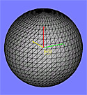 Simply explained, a STL file is a format used by Stereolithography
software to generate information needed to produce 3D models on Stereolithography
machines. A stl file is a triangular representation of a 3D object. The surface
of an object is broken into a logical series of triangles (see illustration at
right). Each triangle is uniquely defined by its normal and three points
representing its vertices. The stl file is a complete listing of the xyz
coordinates of the vertices and normals for the triangles that describe the 3D
object. The extension 'stl' is derived from the word
'Stereolithography'.
Simply explained, a STL file is a format used by Stereolithography
software to generate information needed to produce 3D models on Stereolithography
machines. A stl file is a triangular representation of a 3D object. The surface
of an object is broken into a logical series of triangles (see illustration at
right). Each triangle is uniquely defined by its normal and three points
representing its vertices. The stl file is a complete listing of the xyz
coordinates of the vertices and normals for the triangles that describe the 3D
object. The extension 'stl' is derived from the word
'Stereolithography'.
When creating a STL file, the goal is to achieve a balance between unmanageable file size and a well-defined model with smooth curved geometries. Most CAD software packages offer STL conversion add-ins. If you have access to conversion software, STL translation is relatively simple as long as you have a clean-surfaced 3D model and a high-end computer. Traditionally when converting to a STL file, the user is given several options for resolution. Depending upon the size of the model, the geometry of small details, and the overall curvature of the part, the tolerance can typically be set to 0.0254 mm for average models. Small parts or models with fine details may require a tighter tolerance.
RP techniques are well suited to the direct manufacture of anatomical models from computer-aided-tomography (CAT) and magnetic resonance imaging (MRI) data for two reasons: Firstly layered manufacturing techniques enable complex internal features to be accurately reproduced; Secondly the data from such imaging techniques is already in the form of two dimensional slices and such data could be used to drive the part building systems directly. The manufacturer of such models by techniques such as CNC machining is both time consuming and inaccurate because certain features, such as complex internal cavities, cannot be machined.
The standard data interface between CAD software and the machines is the STL file format. An STL file approximates the shape of a part or assembly using triangular facets. Tiny facets produce a higher quality surface. Using an algorithm in the solid modelling package, a STL file is generated. The build file then is transferred to the build machine.
The method of manufacturing objects as a series of horizontal layers poses a unique set of problems, irrespective of the techniques involved in the fabrication of each layer. Some of these problems are technical and may be as a result of hardware limitations while other may be due to the finishing operations. These are boiling issues and has affected it downstream applications. This section is intended to provide some insight into the considerations that must be made when building parts by layered manufacturing techniques.
The accuracy of a rapid prototype depends upon many factors, the most obvious of which are operator capability and system configuration. Other considerations include the time frame in which measurements are taken, environmental exposure and the amount of post-process finish work. Tolerance deviation also depends upon the axis along which measurements are taken.
Upon completion of the prototype, before post
processing,
Although PolyJet has a shrink rate that is nearly
double that of
The larger shrink rates of SLS increase the tendency for the prototype to warp, bow or curl. Also, the SLS process is less predictable and controllable since it relies on raising the temperature of the powders to just below their melting points. Reliance on heat and heat transfer makes SLS dependent on chamber temperature, laser output, and heat retention within the previously sintered powder. Should elevated temperatures be present in the unsintered powder, sintering of the part may cause undesired materials to fuse to the surface.
Consider the Z axis to be along the height of the part in its build orientation. In all processes, the Z-axis can have greater tolerance deviation than in the X Y plane. Some of this inaccuracy results from the layer-additive process common to all RP technologies.
During the slicing of the STL file into the desired layers, there will be round-off error. Should the top or bottom surface of a feature not be coincident with a layer, the surface height will be adjusted so that it is represented by the thickness of one layer. The combined rounding error between the top and bottom surface could exceed the thickness of one layer. In this respect, PolyJet has the advantage because of its inherently thinner layers.
Z growth also affects dimensions in this axis.
In
The slicing process produces a set of horizontal cross sections and, in a horizontal plane, each of these sections conforms to the geometry of the original Computer Aided Design (CAD) model to a degree of accuracy which is really significant to the entire process. However, each layer is of continuous cross section through its thickness (i.e. in the Z-direction), and therefore parts cannot accurately conform to the CAD geometry in the vertical plane. This is best illustrated by considering the situation shown in the figure below. A cylinder has been built with its circular cross section parallel to the slice axis, i.e. perpendicular to the layers. If any single part layer is considered, it can be seen that the slicing software has produced a layer, the top surface of which conforms precisely to the CAD geometry. However, because the layer is rectangular in cross section it cannot conform to the curve surface across its entire thickness, the largest deviation at its bottom surface. This result in the stepped effect showed which has been termed the stair-stepping phenomenon.
It is clear from the example shown in figure that the smaller the slice thickness, the greater the resolution of the final part. It may seem sensible to use the smallest possible layer thickness that can be physically created by the system, but the smaller the layer thickness, the more slices are required resulting in longer data processing time, larger data files and a longer build time. To optimize the process, variable layer thickness may be used over different ranges of the part. The example of the funnel shown in figure (b.) has a fine layer thickness where the surfaces are sloped and stair-stepping is more pronounced, and thicker layers on the vertically sided sections.
In the two examples provided so far it is the top surface of each layer which conforms to the CAD geometry and this is the case in many of the commercially available systems. The reason for this can be seen if we consider the SLA process in which a laser beam is guided across the surface of a vat of liquid polymer, tracing out the geometry of each layer, and whenever the laser strikes the resin a small volume is cured and solidified to a depth dependent on laser power and scan speed. The top surface of the layer must conform to the CAD geometry because that is what actually drawn on the resin surface, with a continuous depth cured below it providing the layer thickness. On figure (c.) are shown three different ways in which the layers might conform to the CAD geometry, in each case the shaded areas represent the deviation from the true geometry. Example (i) shows the case where the top of each section conforms to the required layer outline, as seen in the those process that form each layer from the top downwards, and example (ii) shows the opposite case in which layers are formed from the bottom up. It is clear from these examples that extent of deviation will be dependent of the gradient of the sloping surface, and whether the error is positive or negative will depend on the direction of slope. In many cases the most favourable situation would be where all
In any manufacturing technique the work-piece must be mounted or supported in some way in preparation for processing, for example held in the vice of a machine tool or the chuck of a lathe. The majority of rapid prototyping processes also require to be mounted to hold it in position, and further structures are often required to support unstable geometries as they are built. The principal benefits achieved by these systems stem from the fact that the processes are fully automated and that part specific fixtures or tooling are not required, and therefore it is not possible to manually position prefabricated fixtures and still reap the same benefits. However the fact that rapid prototyping systems fabricate whatever is described by the CAD input means that they can build any support structures in the way that they build the parts, thereby maintaining their flexibility and automated nature.
Early on in the development of these technologies the support structures were designed on the CAD systems in conjunction with the part, but this was labour intensive and the operator was required to have a full understanding of the part building process. Since then a number of software packages have been developed which generate the design of any required supports automatically by inspecting the part geometry and assessing what is required. The support designs are then sliced in the way as the part and incorporated into the build information sent to the fabricator. The supports are fabricated in the same way as the part and are incorporated into it, but are normally in the form of grids of very thin webs which may easily be removed once the part is complete.
Often, material properties are a critical part of the decision making process. When this is true, selection can be difficult due to trade-offs in factors such as accuracy and surface finish. If material properties are the primary concern, it is best to select the appropriate material and then evaluate the capabilities of the technologies that utilise that material.
It is important to take some caution when reviewing vendor-supplied material properties. Although there are testing standards, variances in build parameters, machine type and elapsed time can yield significant deviations in the results. Vendors may tend to select the testing conditions that present their materials most favourable results.
The materials used to produce rapid prototypes are classified as Liquids, powders, filament and foil.
Developed by DTM Corporation, SLS is widely
used for functional applications. SLS is a process that was patented in 1989 by
Carl Deckard, a
The SLS process creates three-dimensional objects, layer-by-layer, from powdered materials. Heat from a CO2 laser fuses the powder within a precisely controlled process chamber.
Figure Selective Laser Sintering
An SLS machine consists of two powder magazines on either side of the work area. The levelling roller moves powder over from one magazine, crossing over the work area to the other magazine. The laser then traces out the layer. The work platform moves down by the thickness of one layer and the roller then moves in the opposite direction. The process repeats until the part is complete.
While
The surface of an SLS part is powdery, like
the base material whose particles are fused together without complete melting.
The smoother surface of an
Both SLS and
Figure Schematic Fused Deposition Modelling
The FDM process was developed by Scott Crump in 1988. FDM utilizes a temperature-controlled head to extrude thermoplastic material layer by layer. The fundamental process involves heating a filament of thermoplastic polymer and squeezing it out like toothpaste from a tube to form the RP layers.
As the nozzle is moved over the table in the required trajectory, it deposits a thin bead of extruded plastic to form each layer. The plastic solidifies immediately after being ejected from the nozzle and bonds to the layer below. The entire system is contained within a chamber which is held at a temperature just below the melting point of the plastic. The FDM process allows a variety of modelling materials and colours, such as polyester, elastomers, ABS and investment casting wax. The machines range from fast concept modellers to slower, high-precision machines.
In addition, FDM can provide superior visualization by highlighting selected features in a different colour. Support material is needed for overhanging geometries and is later removed by breaking it away from the object. A water-soluble support material which can simply be washed away is also available.
FDM is fairly fast in building small parts on the order of a few cubic inches, or those which have tall, thin form-factors. However, it could be very slow for parts with wide cross sections.
Developed by 3D Systems, Inc., this is the
most widely used RP technology.
Although
Figure Stereolithography
The
Once all the layers are drawn and the model is complete, the platform rises out of the vat and the excess resin is drained. The model is then removed from the platform, washed of excess resin, and then placed in a UV oven for a final curing. The part is then hand finished to the customer requirement.
Because of the layered process, the model has a surface composed of stair steps. Sanding can remove the stair steps for a cosmetic finish. Model build orientation is important for stair-stepping and builds time. In general, orienting the long axis of the model vertically takes longer but has minimal stair steps. Orienting the long axis horizontally shortens build time but magnifies the stair steps. For aesthetic purposes, the model can be primed and painted.
During fabrication, if extremities of the part become too weak, it may be necessary to use supports to prop up the model. The supports can be generated by the program that creates the slices, and the supports are only used for fabrication.
Profiles of object cross sections are cut from paper or other web material using a laser. Material is usually a paper sheet laminated with adhesive on one side, but plastic and metal laminates are appearing. The paper is unwound from a feed roll onto the stack and first bonded to the previous layer using a heated roller which melts a plastic coating on the bottom side of the paper. The profiles are then traced by an optics system that is mounted to an X-Y stage.
Figure Laminated Object Manufacturing
After cutting of the layer is complete, excess paper is cut away to separate the layer from the web. Waste paper is wound on a take-up roll. The method is self-supporting for overhangs and undercuts. The excess material supports overhangs and other weak areas of the part during fabrication. Areas of cross sections which are to be removed in the final object are heavily cross-hatched with the laser to facilitate removal. It can be time consuming to remove extra material for some geometry. Once completed, the part has a wood-like texture composed of the paper layers. Moisture can be absorbed by the paper, which tends to expand and compromise the dimensional stability. Therefore, most models are sealed with a paint or lacquer to block moisture ingress.
In general, the finish, accuracy and stability of paper objects are not as good as for materials used with other RP methods. However, material costs are very low, and objects have the look and feel of wood and can be worked and finished in the same manner. This has fostered applications such as patterns for sand castings. While there are limitations on materials, work has been done with plastics, composites, ceramics and metals. Some of these materials are available on a limited commercial basis.
Variations on this method have been developed
by many companies and research groups. For example, Kira's Paper Lamination
Technology (PLT) uses a knife to cut each layer instead of a laser and applies
adhesive to bond layers using the xerographic process. Solido Ltd. of
Objet Geometries Ltd., an Israeli company, introduced its first machine based on PolyJet TM technology in early 2000. It's a potentially promising replacement for stereolithography. The process is based on photopolymers, but uses a wide area inkjet head to layer wise deposit both build and support materials. It subsequently completely cures each layer after it is deposited with a UV flood lamp mounted on the print head. The support material, which is also a photopolymer, is removed by washing it away with pressurized water in a secondary operation. The specifications are similar to laser-based stereolithography systems costing several times as much, and operating conveniences are similar to lower-cost 3D printers. The resulting prototype requires little if any, post processing work for concept and form/fit models.
There is no single answer to which technology one should use. Likewise, the process one selects will inevitably vary by project and perhaps by component. My recommendation is to investigate the ability of the technology to address the requirements for the project.
|
Politica de confidentialitate | Termeni si conditii de utilizare |

Vizualizari: 2252
Importanta: ![]()
Termeni si conditii de utilizare | Contact
© SCRIGROUP 2025 . All rights reserved