| CATEGORII DOCUMENTE |
| Bulgara | Ceha slovaca | Croata | Engleza | Estona | Finlandeza | Franceza |
| Germana | Italiana | Letona | Lituaniana | Maghiara | Olandeza | Poloneza |
| Sarba | Slovena | Spaniola | Suedeza | Turca | Ucraineana |
A Survey of the Recent State of
Department of Telecommunications
Abstract
In this document we would like to
present a survey of the recent state of
Introduction
Simulations are very important part of network and protocol design and development. The reasons are:
Protocol interactions are inherently too complex to analyze.
The scalability of protocols are too expensive to test on large testbeds
It is quicker to simulate than to assemble and configure networks
Conditions are more controlled especially for wireless solutions
These causes are motivating a great deal of interest in developing simulation environments which are providing sufficient tools to analyze the behavior of newly developed protocols and optimization mechanisms of the existing ones.
In this paper we want to shortly introduce a simulation system, named OMNeT++, and the IPv6/MIPv6 simulation module of it, which is the IPv6Suite.
In the first section we make an overview of the work of three working groups in IETF wich are occupied with the standardization of IPv6 and MIPv6 protocols. These are:
IP version 6 Working Group(WG)
Mobility for IPv6 WG
MIPv6 Signaling and Handoff Optimization WG
We summarize the achievements reached already, topics recently in progress and future work especially related to MIPv6.
After this, in the next section we would like make a survey of the basics of the OMNeT++ and IPv6Suite simulation systems. We describe their recent state of simulating MIPv6 and mobility management problems.
In the last section we make a comparison between the recent state of the work of the Internet Engineering Task Force (IETF) Internet-related working groups, and the recent state of the IPv6Suite developments, to see which parts of the protocol simulation are waiting to be developed. As a conclusion we draft up recommendations for future work.
The Work of the IETF Working Groups
In this section we describe the tasks of the three IETF working groups mentioned before. We will present a short overview of the current work and the goals wished to be reached by each working groups. We make a list of the RFCs and Internet-Drafts related to their work. Doing this we aim the goal of throwing light on the importance of developing accurate simulations in this domain.
The IP version 6 Working Group
The IPv6 working group is responsible for the specification and standardization of the Internet Protocol version 6. IPv6 provides a much larger global address space than its predecessor IPv4. This enables global end-to-end communication and restores valuable properties of the IP architecture that have been lost in the IPv4 Internet. The core IPv6 standards are widely implemented and are starting to see global deployment. The primary focus of the IPv6 working group is to complete the standardization of the IPv6 protocols, and to review and update the IPv6 specifications based on implementation and deployment experience, and advancing them on the standardization track az appropriate.
The working group's work items are as follows:
Develop Proxy Neighbor Discovery solution for prefix delegation and publish. This enables a simple site border router to re-advertise downstream a prefix it hears on its upstream link.
Complete 'Default Router Preferences, More-Specific Routes, and 'Load Sharing'.
Update to ICMPv6 (RFC2463) Complete 'Node Information Queries' Update Auto Configuration (RFC2462) and Neighbor Discovery (RFC2461).
Investigate approaches to optimize or eliminate Duplicate Address Detection (DAD) to make reduce the delays incurred by DAD when there is a change of network attachment points.
Update 'Privacy Extensions for Stateless Autoconfiguration' document (RFC3041).
Complete work on IPv6 Node Requirements.
Update the IPv6 Address Architecture to resolve the issues raised in the IAB response to the Robert Elz appeal.
Complete work on Scoped Addressing Architecture.
Update IPv6 over PPP (RFC2472).
Complete work on 'Link Scoped IPv6 Multicast Addresses'.
Now we list the RFCs and Internet-Drafts related to the working group:
Request For Comments:
Internet-Drafts:
Mobility for IPv6 Working Group
Mobile IPv6
(MIPv6) specifies routing support to permit an IPv6 host to continue using its
'permanent' home address as it moves around the Internet. Mobile IPv6
supports transparency above the IP layer, including maintenance of active TCP
connections and UDP port bindings. The specifications for these mechanisms consist
of:
draft-ietf-mobileip-ipv6-24 (RFC XXX) and
draft-ietf-mobileip-mipv6-ha-ipsec-06 (RFC XXX)
The protocol as specified in the above two documents can be considered as
the baseline or minimum protocol set for implementing IPv6 mobility. During the
development phase of the base protocol, a few additional features were
identified as necessary to facilitate deployment (described below).
The primary goal of the MIP6 working group will be to enhance base IPv6
mobility by continuing work on developments that are required for wide-scale
deployments. Additionally the working group will ensure that any issues
identified by the interop testing of the MIPv6 specifications are addressed
quickly. Specific work items with this goal in mind are listed below:
Features such as renumbering of the home link, home agent discovery, Route Optimization, which are currently a part of the base specification can be specified more explicitly as separate specifications. This will also enable modularizing the Mobile IPv6 specification further into the minimal subset and add-on features. Some of these specifications will be identified as base mechanisms of Mobile IPv6.
A number of enhancements to basic IPv6
mobility were identified during the development of the base specification.
These enhancements will be taken up in a phased manner depending on the
priority identified with each. Below are listed the work items to be taken up
by the WG:
A bootstrap mechanism for setting up security associations between the Mobile Node (MN) and Home Agent (HA) that would enable easier deployment of Mobile IPv6. This bootstrap mechanism is intended to be used when the device is turned on the very first time and activates MIPv6. The WG should investigate and define the scope before solving the problem.
Improving home agent reliability: in the event of a home agent crashing, this would allow another home agent to continue providing service to a given mobile node.
Support for a Mobile Node changing its home address, either because of renumbering in its home network or because it periodically changes addresses (perhaps via RFC3041: Privacy Extensions for Stateless Address Autoconfiguration in IPv6)
Route optimization will require security mechanisms for trusting and updating the binding information. Return-routability is the basic mechanism for route-optimization. Mechanisms using a shared secret Key/Security Association will be considered. Methods for establishing a security association between the mobile node and the correspondent node are out of the scope of the WG.
The working group will also document problem statements associated with deploying Mobile IPv6 in the following areas:
Mobile IPv6 issues in the presence of firewalls
Mobile IPv6 deployment and transition issues in the presence of IPv4/IPv6 networks
Multicast issues
It should be noted that there are potential optimizations that might make mobile IP more attractive for use by certain applications (e.g., making handovers 'faster'). The latter category of optimizations is explicitly out-of-scope at this time; this WG will focus on issues for which there is strong consensus that the work is needed to get basic mobility deployable on a large scale, which is at least as important as optimizations.
Now we list the RFCs and Internet-Drafts related to the working group:
MIPv6 Signaling and Handoff Optimization Working Group (MIPSHOP)
As described before Mobile
IPv6 specifies routing support to permit IP hosts using IPv6 to move between IP
subnetworks while maintaining session continuity. Mobile IPv6 supports
transparency above the IP layer, including maintenance of active TCP connections
and UDP port bindings.
To accomplish this, the mobile node notifies its home agent (and
potentially also its correspondent nodes) of the current binding
between its home address and its care of address. This binding allows a mobile
node to maintain connectivity with the Internet as it moves between subnets.
Depending on what steps a mobile node must perform on a new subnet, the lag
between when the mobile node has layer 2 connectivity and when it begins sending
and receiving packets on the new link may be substantial. A mobile node must
first detect at layer 3 that its point of attachment has changed, then it must
perform configuration on the new link, including router discovery and
configuring a new care of address. After that, the mobile node must perform
binding updates with the home address and any correspondent nodes. Since many
layer 2 mobility technologies require that the mobile node drop its link
connectivity to the old subnet when moving, any packets between the correspondent
node and the mobile node sent or in-flight during this time arrive at the old
care of address, where they are dropped. Such packet loss may have significant
adverse effects.
The Mobile IP Working group had previously been developing two technologies to
address the issues of signaling overhead and handoff latency/packet loss:
These two technologies can be used separately or together to reduce or eliminate signaling overhead and packet loss due to handoff delays in Mobile IPv6.
Scope of MIPSHOP:
The MIPSHOP Working Group will
complete the FMIPv6 and HMIPv6 work begun in the Mobile IP Working Group.
Specifically, the WG will:
There are security issues that arise because of the highly dynamic nature of the security relationships between, say, a mobile node and its mobility anchor points, or between a mobile node and its access routers in a fast handover scenario. The working group is not required to provide solutions to all these issues before publishing its experimental and informational protocols. The working group will document the security requirements and the shortcomings of the solutions in the corresponding protocol specifications. This will provide valuable feedback to other groups or subsequent efforts.
Now we list the RFCs and Internet-Drafts related to the working group:
No Request For Comments!!!
OMNeT++ and IPv6Suite
In this section we take a look at the basics of OMNeT++ (Objective Modular Network Testbed in C++) and the IPv6Suite simulation frameworks. These are developed mainly by Ahmet Sekercioglu and his team at the Shool of Electrical and Computer Systems Engineering, Monash University, Melbourne, Australia.
OMNet++ Basics
OMNeT++ is a discrete event simulation environment. Its primary application area is the simulation of communication networks, but because of its generic and flexible architecture, is successfully used in other areas like the simulation of complex IT systems, queuing networks or hardware architectures as well. OMNeT++ provides component architecture for models. Components (modules) are programmed in C++, and then assembled into larger components and models using a high-level language (NED). Reusability of models comes for free. OMNeT++ has extensive GUI support, and due to its modular architecture, the simulation kernel (and models) can be embedded easily into your applications.
Although OMNeT++ is not a network simulator itself, it is currently gaining widespread popularity as a network simulation platform in the scientific community as well as in industrial settings, and building up a large user community
Now, here is a shot overview of functionalities and simulation modells provided by OMNeT++:
TCP/IP networks simulation set:
LAN/MAN protocols simulation set:
Mobility and ad-hoc frameworks, wireless protocols simulation set:
Figure 1 shows an overview of the simulation activities in the domain of OMNeT++:
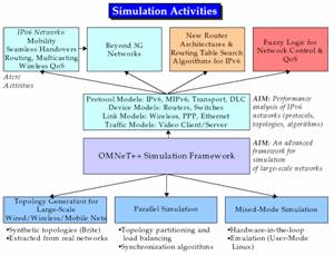
Figure 1. Simulation Activities in OMNeT++
An OMNeT++ model consists of modules that communicate with message passing. The active modules are termed simple modules; their code executes quasi in parallel (simple modules are implemented with lightweight processes or coroutines.) Simple module code is written in C++, using the simulation class library. Messages can contain arbitrarily complex data structures. Messages can be sent either directly to their destination or through a gate (in this case, the message travels along a predefied path, though a series of connections.)
Simple modules can be grouped into compound modules and so forth, as shown in figure 2. And this is not limited. The notion of simple and compound modules directly parallel with DEVS atomic and coupled models (anyway, OMNeT++ has nothing to do with DEVS). There is a separate topology description language for defining compound module types. The language has a simple syntax, yet it is very powerful: for example, it is possible to define a hypercube network with the size as parameter.
Figure 2. Module Hierarchy in OMNeT++
Some of the main features you can use while writing simulations are:
Simple modules are active elements in a model. They are atomic elements in the module hierarchy: cannot be divided any further. The user implements the simple modules in C++, using the OMNeT++ simulation class library. The functionality of a simple module is concentrated into a single function called activity(). Activity() usually contains a loop with send and receive calls to send and receive messages. During simulation execution, simple modules appear to run in parallel, because they are implemented as lightweight processes (coroutines).
Both simple and compound modules are instances of module types. While describing the model, the user defines module types; instances of these module types serve as components for more complex module types. Finally, the user creates the system module as an instance of a previously defined module type; this is how the all modules of the network are instantiated.
When a module type is used as a building block, there is no distinction whether it is a simple or a compound module. This allows the user to split a simple module into several simple modules within a compound module, or vica versa, re-implement the functionality of a compound module in one simple module, without affecting existing users of the module type. This is entirely transparent.
Module types can be stored in files separately from the place of their actual usage, which means they are reusable.
Modules communicate with messages. Messages can contain arbitrarily complex data structures. Simple modules can send messages either directly to their destination or along a predefined path, through a gates and connections.
Gates are the input and output interfaces of modules; messages are sent out through output gates and arrive through input gates. An input and an output gate can be linked with a connection (also termed link).
Connections are created within a single level of module hierarchy: within a compound module, corresponding gates of two submodules, or a gate of one submodule and a gate of the compound module can be connected.
Due to the hierarchical structure of the model, messages typically travel through a chain of connections, to start and arrive in simple modules. Compound modules act as 'cardboard boxes' in the model, transparently relaying messages between their inside and the outside world.
Connections can be assigned properties such as propagation delay and bit error rate. One can also define connection or link types.
Modules can have parameters. Parameters are used for three purposes:
Parameters can take string, numeric or pointer values; numeric values include random variables from different distributions, values input interactively by the user, and expressions.
Numeric-valued parameters can be used to construct flexible topologies. Within a compound module, parameters can define the number of submodules, number of gates, and the way the internal connections are made.
Compound modules can pass parameters or expressions of parameters to their submodules. Parameter passing can be done by value or by reference.
During simulation execution, if a module changes the value of a parameter taken be reference, the changed value propagates to other modules.This effect can be used as a second means of module communication. Pointer-valued parameters can be used to implement shared memory.
The user defines the structure of the model in NED language descriptions (or in a graphical editor, but it also produces NED).
Here's a quick step-by-step overview of how you would use OMNeT++ in solving a simulation problem:
IPv6Suite is an open source OMNeT++ model suite for accurate simulation of IPv6/ MIPv6 protocols and networks. This simulation suite models the functionality of the following RFCs:
and the following Internet Drafts:
and also has models for the following standards to simulate wireless LANs:
Conditions Today
Now after we made a short summary of the OMNeT++ and IPv6Suite simulation frameworks, we are trying to make an overview of the crrent state of the IPv6Suite in modeling IPv6 and especially MIPv6 protocols. We will do this in three steps. The first chpter describes the basic IPv6 simulation approaches. This allows us to make a comparison with the work of the IETF working group named IP version 6 WG. In the following two chapters we plan to use the same approach first related to the Mobile IPv6 (MIPv6) protocol and at last related to mobility management protocols such as Hierarchical MIPv6, FMIPv6, etc.. The following chapters summarise results of the work of Ahmet Sekercioglu and his team at the Shool of Electrical and Computer Systems Engineering, Monash University, Melbourne, Australia, who can be introduced as the main developers of OMNeT++ and the IPv6Suite.
Modeling of IPv6 Protocols
As part of the ongoing research program on performance analysis of protocols for mobility management in IPv6 networks, there have developed a set of OMNeT++ models for accurate simulation of IPv6 protocols. This simulation set models the functionality of the RFC 2373 IP Version 6 Addressing
Architecture, RFC 2460 Internet Protocol Version 6 (IPv6) Specification, RFC 2461 Neighbor Discovery for IP Version 6 (IPv6), RFC 2462 IPv6 Stateless Address Autoconfiguration, RFC 2463 Internet Control Message Protocol (ICMPv6) for the Internet Protocol Version 6 (IPv6) Specification, and RFC 2472 IP Version 6 over PPP. And at the time of writing the functionality of RFC 2374 (An IPv6 Aggregatable Global Unicast Address Format), 2464 (Transmission of IPv6 Packets over Ethernet Networks), 2473 (Generic Packet Tunneling in IPv6 Specification), 3755 (Mobility Support in IPv6)
OMNeT++ have been choosen as the simulation framework because of the following reasons:
This IPv6 simulation model suite consists of several functional blocks. There is also dual-stack support for analysis of protocol interactions in mixed IPv4-IPv6 networking environments. Realistically formatted protocol data units (PDUs) are passed between simulated network entities and service data units (SDUs) exchanged between the adjacent protocol layers. The IPv6 datagram format currently includes most of the extension headers except the ones related to Authentication and Encapsulating Security Payload. Real data from the network testbed is used to calibrate the model, and simulated processing delays are introduced where necessary to account for the differences without sacrificing performance.
As mentioned before the IPv6 simulation model suite consists of several functional blocks. As one can expect, the major blocks reside in the network and data link control layers. These blocks can be connected together to form simulated hosts, routers, Ethernet hubs, point-to-point links etc. The core module (IPProcessing) of the network layer provides dual-stack support (IPv4 and IPv6). The simulation model provides enhancements to the existing OMNeT++ IPv4 models mainly in the areas of providing interchangeable network interfaces for simulating IP protocols using various physical transport mechanisms (point-to-point links, Ethernet connections etc.). The enhancements also include the ability to model nodes having any combination of these physical devices. A router in an IPv6 network has many configurable parameters. From a users point of view any approach that can reduce the learning curve involving a new simulation tool will be very useful. For this reason, there have chosen Extensible Markup Language (XML) as the format for the configuration file of the network nodes. The reasons behind this approach can be summarized as follows: XML is easy to comprehend, non-proprietary and mature technology with many tools
available (parsers, viewers and validators etc.).
The architectural framework of the IPv6 simulation model is based on the structure of the OMNeT++ IPv4 Protocol Suite. The IPv4 suite consists of modules that model the data link control, network and transport (TCP and UDP) layers. The IPv6 simulation model framework is interoperable with the IPv4 models to support modeling dual stack routers which allow IPv4 and IPv6 packet flows simultaneously. The suite also allows various data link control layer network interfaces to be present within a single node. Therefore, it is possible to investigate the interactions between IPv4 and IPv6 protocols in a mixed protocol environment. It is belived that the introduction and integration of IPv6 into the current global IPv4 infrastructure will raise performance issues that need to be investigated in large scale simulated networking scenarios.
There have been adopted a different approach than the design of the IPv4 Protocol Suite, and separated the network interface from the network layer. This approach has allowes to add new models of physical interfaces and to simulate routers that can have a combination of various network cards. In
the simulation suite, the network layer contains only the IP processing, IP input queue and the IPv4 routing table modules. The main functional blocks of the IP processing module are as follows: The IP discriminator (ipd) module checks the IP version and forwards the packets to the correct IP stack. The IP combine (ipc) receives the packet from either the IPv4 or IPv6 stack and forwards the packet to the data link control layer.
The Data link control layer module contains the input queue and an interchangeable network interface. This arrangement allows one to accommodate different physical transports without a need of recompilation of simulation models. PPP and Ethernet interfaces have been implemented. The Ethernet model also includes a hub.
The core functionality of the IPv6 Simulation model is implemented in the IPv6 processing compound module. This module determines the destination of packets, initiates and receives ICMP notifications, and implements Neighbour Discovery mechanisms. The compound module IPv6Processing consists of the following submodules:
Datagrams arriving a node will encounter the PreRouting6 module first. In this module, a hook can be implemented to gather statistics or filter packets.
Next hop determination is the responsibility of the Routing6 module. Its options are:
LocalDeliver accepts datagrams destined for the local node, decapsulates the datagram and delivers its contents to upper layers. Any destination options encountered in the datagram are also processed here. The AddressResolution module queries neigbhours for their data link control layer address and responds
to the same requests issued by neighbouring nodes. It aims to follow the prescribed procedures defined in RFC 2461 as closely as possible.
Determination of the next hop neighbour is accomplished in Routing6 as mentioned previously with the aid of the simple module RoutingTable6, which contains the conceptual data structures mentioned in Section 5.2 of RFC 2461. Many other simple modules rely on RoutingTable6 to provide access to those structures, notably NeighbourDiscovery, Multicast and AddressResolution.
IPv6Send encapsulates the upper layer SDUs into IPv6 datagrams and sends them to Routing6 for further processing. The IPv6Fragmentation module accepts outgoing datagrams from Routing6 and checks to see if fragmentation is required before transferring the packets to IPv6Output module. ICMP packets are managed by the ICMPv6 compound module. It contains three simple modules ICMPv6Core, NeighbourDiscovery (nd) and ICMPCombine (combine). The ICMPv6Core module implements most of the RFC 2463.
The NeighbourDiscovery simple module initiates and responds to neighbour discovery messages according to the role of the node (host or router) in conformance with RFC 2461. AutoConfiguration has also been added in accordance with RFC 2462 .
The accuracy of the simulation is ensured due to the fine-grained level of detail in the simulation. Datagrams are passed between network entities and SDUs exchanged between the adjacent protocol layers. The IPv6 datagram currently implements most of the extension headers except
the Authentication and Encapsulating Security Payload headers. Real data from simple network testbed is used to calibrate the model. Simulated processing delays are introduced where necessary to account for the differences without sacrificing performance.
The network configuration (i.e. the connections between the network entities) is described through OMNeT++s NED language. In addition to this, for each IPv6 node, a set of parameters can be configured by writing an XML document. There are two ways to configure parameters of a node. In the <global> section, a parameter for all interfaces of all nodes on the same network is set, and in the <local> section, a particular parameter on a specific interface of the node is set.
Modelling of Mobile IPv6 Protocols
The simulation model consists of three key components:
Mobility for IPv6, or Mobile IPv6 (MIPv6) was developed to allow an IPv6 node to change points of network attachment without disrupting applications or services. In the MIPv6 specification, three network roles: mobile node, correspondent node and home agent are essentially defined. A mobile node is a node that can change its point of attachment from one link to another, while still being reachable via its home address. The mobile node maintains two IPv6 addresses, home address and care-of address. The home address is used as a permanent address of the node and is also used as an identifier by the transport sessions. The care-of address is essentially used as a current location identifier of the mobile node by the home agent. It also allows the correspondent node to send packets directly to the mobile node. A correspondent node is a peer node with which a mobile node is communicating. A home agent is a router on the mobile nodes home link with which the mobile node notifies its current care-of address. While the mobile node is away from home, the home agent intercepts
packets on the home link destined to the mobile nodes home address, encapsulates them, and tunnels them to the mobile nodes registered care-of address.
There have been developed a comprehensive set of models for simulating fixed IPv6 networks. Accurate modeling of MIPv6 protocol in the simulation will allow to extend the simulation suite into MIPv6 protocol performance analysis, such as signaling and handover optimisations, network mobility, and multicast mobility.
The MIPv6 simulation model contains functionalities such as handling of various IPv6 headers and conceptual data structures to manage different aspects of the protocol. The implementation is designed in a way such that each module in the protocol stack handles a specific type of IPv6 header or an ICMP message. The MIPv6 model interacts with higher layer protocols via LocalDeliver and Send modules. The IPv6 packet is sent to the network through
Output and received from PreRouting. The ICMPv6 Ping echo and reply messages are processed in the ICMP module.
According to Neighbour Discovery in IPv6, the main difference between a host and router is the handling of different control messages necessary for neighbour discovery such as router advertisement, router solicitation, neighbour advertisement and neighbour solicitation. Therefore, a class inheritance approach is used to express the relationships between a router and host as it also allows the transition between the two roles. Only one instance of inherited class is created depending on whether the node is a router or host at startup . The instance is created in Neighbour Discovery, a simple module that resides in ICMP module. This approach provides extensibility when adding MIPv6 extensions, particularly the signaling and handover optimisations by allowing new subclasses to reuse the capabilities of the base class as well as override certain functions to test different algorithms accordingly.
The mobile node, correspondent node and home agent process the messages differently. This is done in the Mobility module. The Mobility module
also implements a class inheritance approach. The base class MIPv6MobilityState provides the common behaviour for the different MIPv6
roles. The assignment of a node to a specific MIPv6 role is done via XML configuration.
In the MIPv6 specification, the conceptual data structures are described as follows:
The base class MIPv6CDS contains the binding cache. The mobile node interface contains binding update list and the home agent contains the home agent list. The instance of specific interface is instantiated in Mobility module. As the node is assigned to a particular MIPv6 role, the specific class instance is created accordingly.
Most of the MIPv6 functionalities have been implemented in the simulation model. However, there is a number of attributes, which is still under consideration and may be implemented in the future. It includes:
Performance Evaluation of Mobility Management Protocols for the Next Generation Internet
/*BEVEZETŐ SZVEG*/
Access Router Localised Handover Extensions
Handover latency is defined as the interval starting from the moment when the mobile node leaves the old access medium until it resumes communication with the Corespondent Node (CN) at the new access medium. This is shown in Figure 3.
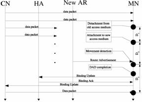
Figure 3. Handover latency components for Mobile IPv6
There are three components to handover latency. The first D is the Layer 2 (L2) handover latency i.e. the link layer specific handover procedure. D is the time taken by the Mobile Node (MN) to detect the presence of a new Access Router (AR) at the new access network and configure a new Care-of Address (CoA). This is also known as the rendezvous time delay. Rendezvous time is affected by the amount of overlap or distance between the two neighbouring coverage areas of the Access Point (AP)s, the speed of the mobile node and the rate of unsolicited Router Advertisement (RA) beacons. The third component D is the time it takes to send a Binding Update (BU) back to the Home Agent (HA)/CN and the subsequent resumption of communications indicated by a new data packet arriving at the MN from the new AR. This is also known as the registration delay.
L2 handovers are not discussed any further in this paper as they depend on the specific physical transport technology and nothing can be done to alter its behaviour at the network layer. The rendezvous time is affected by the frequency of router advertisements. Registration delay is affected by the path delay and packet loss of the path the BU takes from the MN to the HA in the Internet.
There are basically two varieties of handover management techniques, predictive and non-predictive. The predictive varieties tend to require assistance from the network infrastructure, functionality that is usually not built into the system. It is predictive because it predicts which wireless link and hence subnet the MN will move to before the actual handover. Non-predictive handovers in general do not require special assistance from the wired infrastructure and are reactive in nature i.e. it will perform an L3 handover only after it has detected a transition to a different L3 subnet. As a general rule of thumb predictive handovers are much more complex to implement and manage.
Fast Handovers for Mobile IPv6 (FMIP)
An example of a predictive handover technique is Fast Handovers for Mobile IPv6 (FMIP). It can reduce both the rendezvous and registration delay by anticipating handover before it happens and carrying out some of the time consuming operations before the actual L2 handover occurs. This requires modifications to the ARs. FMIP forms a temporary tunnel between the Previous Access Router (PAR) and the Next Access Router (NAR), thereby allowing the MN to receive packets at the NARs access network before the MN has finished its registration and established itself with the NAR. There are three stages to this process: handover initiation, tunnel establishment and packet forwarding, abbreviated as HI, TE and PF.
Handover initiation is usually initiated by the MN. The coverage areas of the two ARs have to overlap in order for anticipated fast handover to occur. Otherwise there is a break in communications with the duration dependent on the size of the gap and how fast the MN is moving through this no coverage zone. (The nonanticipated case as supported by 802.11b access networks out of the box shall be discussed next). The MN knows that it should handover to NAR when it receives a L2 indication usually called an L2 trigger due to perhaps waning received signal strength from PAR below some threshold level or other factors unrelated to link quality. The MN sends a Router Solicitation for Proxy (RtSolPr) to its current AR i.e. PAR with the link layer identifier of the prospective access point e.g. base station ID. This information is provided by the specific L2 technology. The PAR responds by sending a Proxy Router Advertisement (PrRtAdv) with the NARs link layer address, its IP address and also any network prefixes to enable the MN to generate a suitable new care-of address (NCoA) on the new link. If the network is the one to initiate the handover then it will send an unsolicited PrRtAdv to the MN.
Tunnel establishment involves the MN sending a Fast Binding Update (FBU) some time after receiving the PrRtAdv. Once PAR receives FBU, it will send a Handover Initiate (HI) to NAR. The purpose of HI is to establish a bidirectional tunnel between PAR and NAR to allow use of the previous care-of address (PCoA) on NARs link as well as to validate whether the NCoA is valid and unique at NARs link. When NAR receives HI it will set up a host route for MNs PCoA by creating a neighbour cache entry that points to PCoA with state of STALE i.e. address resolution required. NAR should also defend NCoA via proxy neighbour advertisement for a short period of time after verifying uniqueness of NCoA. NAR sends back a Handover Acknowledge (HACK) to PAR. PAR will subsequently send a Fast Binding Acknowledgement (FBACK) to MN. Upon receiving FBACK, the MN will know that it has permission to use NCoA on the new link.
Once the MN has arrived at the new link, it will send a Router Solicitation (RS) to the AR on this link which should be NAR. Attached to this RS is a Fast Neighbour Advertisement (FNA) which is just an IPv6 address option with the NCoA inside it. The purpose of this is to notify the NAR to stop defending the NCoA if the NAR had previously set up a proxy neighbour cache entry. The FNA will also start the forwarding of packets addressed to PCoA to the MN on this new link by creating a neighbour cache entry at NAR that points to PCoA as been on-link and with state of REACHABLE i.e. address resolution not required. If the FBACK had indicated NCoA was acceptable then MN can start using that as source address after sending BU to HA and CNs. However if FBACK indicated that NCoA could not be verified by NAR for whatever reason then the Neighbour Advertisement Acknowledge (NAACK) option is included in NARs Router Advertisement (RA) to again indicate if NCoA is valid or not. If both responses say that NCoA is invalid then normal IPv6 address configuration process.
The non-anticipated case holds more promise for a simple and still effective mechanism at reducing packet loss and reducing handover latency without the coupling to specific L2 technologies required by the anticipated case discussed above. Non-anticipated fast handovers do not require knowledge of which AR will be the NAR. There is no exchange of PrRtAdv or RtSolPr at PARs link. In fact the Handover Initiation phase does not occur at all. The MN upon attaching to new link (NARs link) as indicated by reception of a L2 link up trigger will send a RS with FNA. This is required to learn the default routers i.e. NARs IP and link layer address. Then send a FBU to the PAR using its CoA (PCoA) as source address. The NAR if it supports FMIP has to allow in its ingress filtering rules any packets destined to PAR with a source address belonging to PARs subnet, in this case PCoA fulfils this criteria as it has been autoconfigured via the IPv6 address configuration mechanism. Once FBU reaches PAR, the PAR will quickly do the HI and HACK exchange to complete the tunnel establishment stage. The NAR should not need to verify the NCoAs uniqueness nor defend it. In fact it should leave all NCoA configurations to the MN because there is now no advantage in having it done by NAR unless stateful address configuration is used. In the meantime the MN can use the PCoA as if it still existed on the old link as a bidirectional tunnel should have been established between PAR and NAR by then. Reception of a BACK from the PAR is confirmation of tunnel establishment. If we take the view that the wireless link delay is much greater than the delay existing on the link between PAR and NAR then packet loss should be minimised. The MN is also free to simultaneously configure NCoA as done in MIPv6 as soon as it receives the RA that should include a NAACK indicating that NCoA is invalid to force MN to do address configuration. The non-anticipated case while not able to reduce the rendezvous time to zero as the anticipated case promises to, it can reduce the overall handover latency as packets are forwarded quickly from the PAR to the NAR and allows the MN to resume communication via the PAR to NAR tunnel without waiting for registration with HA to complete as base MIPv6 would require. It buys the MN additional time to perform Duplicate Address Detection (DAD) and binding updates without interrupting communications.
Layer Two Link Up Trigger
In reactive handovers there is a delay at the MN associated with recognizing a new Layer 3 or Network Layer (L3) point of attachment called the rendezvous time. The previous section mentioned the use of the full complement of L2 triggers to implement FMIP. Since this would require some modification of existing L2 technology it would be a rather expensive exercise. The link up trigger (L2 Trigger) that is commonly implemented in virtually all wired and wireless devices is the link up trigger which from now on will simply be referred to as L2 Trigger.
This simple notification from L2 can help to reduce rendezvous time because it detects a change in the L2 link. Whilst it is possible that a L2 handover is not associated with an L3 handover this mis-prediction will have cost only a RS and the corresponding RA to tell the MN it had not changed L3 point of attachment and so should not initiate L3 handover. So the benefits for L2 Trigger should outweigh by far the cost except in situations where there are frequent L2 handovers or moving in and out of range of a solo coverage range so that large numbers of MNs performing router discovery could take up considerable bandwidth. This is not really too much of an issue in deployment because if the MN is residing at the periphery of the coverage range then the coverage range should be extended by adding extra APs or the MN has to restrict its mobility within the existing coverage range.
Fast Solicited Router Advertisements
During router discovery, when a mobile node sends a Router Soliciation (RS) and awaits the Router Advertisement (RA) from the local subnet router, there is a random amount of time before the RA is sent back in response as specified in RFC 2461 (Neighbor Discovery for IP Version 6). This is so that Router Advertisements on the local subnet are desynchronised in cases where more than one router exists to prevent flooding of the network and collisions on common broadcast media like Ethernet. 0 to MAX RA DELAY TIME (500ms default). This is where an amendment to RFC2461 called Fast Router Advertisements can help. It is especially tailored for ARs that will have MNs visiting their links, as an expeditious solicited RA can reduce the rendezvous delay and hence the overall handover latency. This is achieved by choosing one router on the link to serve as the fast RA router. Only that designated router is allowed to respond immediately with a unicast RA to a mobile node that sends a RS with a proper any valid address besides the unspecified address source address. There is an allowance for fast RAs up to a configurable maximum of FastRACounter that is 10 by default. Any more RSs beyond that will be scheduled for a normal unsolicited multicast RA as described in RFC 2461.
Optimistic Duplicate Address Detection
Optimistic DAD is an Internet draft describing a method of allowing a node to use a tentative address i.e. an address undergoing DAD as source address which is contrary to the standard behaviour. It operates under the assumption that the addresses chosen for DAD on a particular link layer technology are well distributed so as to minimise the chance of duplicate addresses. This is certainly true of Ethernet based technologies such as IEEE 802.11b. Nodes implementing Optimistic Duplicate Address Detection (ODAD) will be able to resume communications much earlier after a handover by carrying out standard DAD in parallel.
ODAD enforces certain restrictions on what can be done with the tentative address so that disruption to the legitimate node who actually owns the tentative address will be minimal. This guarantee is enforced by the following:
There is also a procedure to generate a new random suffix and hence form another IP address to undergo DAD. This is a simple method to automatically recover from duplicate addresses since the standard behaviour in IPv6 calls for manual intervention.
Previous Care-of Address Forwarding
Previous care-of address Forwarding was described in earlier revisions of the MIPv6 Internet draft. It was removed due to security considerations. Previous care-of address Forwarding (PCoAF) is the MIPv6 equivalent of smooth handover from MIP.
PCoAF uses only stock MIPv6 functionality. The MN regards the previous access link as its home subnet and sends a BU to PAR with the HoA set to the PCoA and the CoA to the NCoA. Messages destined for the MN at PCoA will be intercepted, encapsulated and forwarded by PAR to the MN at its NCoA.
PCoAF mitigates the effects of a topologically distant HA or CN by using the PAR to forward the packets addressed to the PCoA while the BU is sent to the HA and CN. This ensures a minimal number of lost packets when the traffic type is of the multimedia variety and the MN seldom acknowledges received packets i.e large synchronisation buffer so that the MN does not need to acknowledge packets during the handover in order to continue receiving packets.
This is also functionally similar to the non-anticipated fast handovers, discussed previously, in terms of been able to reduce the number of dropped packets after handover. Whilst non-anticipated fast handovers may have the upper hand by allowing the MN to resume communications using its PCoA as soon as it has detected movement to NAR and thus a greater reduction in the number of dropped packets, this comes at a cost of adding fast handover functionality at the edge of the network which is not a trivial task, and an additional overhead of signalling messages between PAR and NAR. All PCoAF requires is that all ARs have HA functionality. However with the addition of ODAD, and Fast Solicited Router Advertisement (FSRA) this mechanism is at least as fast as non-anticipated fast handovers and can come close to the anticipated version. Close only because in anticipated mode of fast handovers the task of establishing a forwarding tunnel is accomplished just before handover whilst in the combined version of PCoAF there will still be some delay in configuring a CoA on new link and sending a BU to PCoA.
While these AR local extensions can improve handover times, they still can not solve the problem of excessive signalling that occurs when the MN moves frequently within a small geographical area while away from home. When the MN moves just beyond limit of link layer connectivity to its previous subnet, it needs to send a BU all the way to the HA even when it may be moving back soon into the previous cells coverage range. MIPv6 was not designed with this in mind since its sole purpose was to allow Internet access on the move albeit not seamlessly and efficiently though. These shortcomings led to the development of localised mobility management protocols which are the subject of the next chapter.
Localised Mobility Management (LMM)
MIPv6 handovers are subjected to variable delays as the signaling between the MN and the correspondent entities introduce varying latencies that magnify the bursty packet-switched nature of the Internet where network applications are already subjected to non-deterministic delays arising from congestion. Real time protocols demand stringent bounds on delay for packet delivery, otherwise noticeable degradation in quality occurs. As the MN moves over different provider networks as shown in Figure 4, it signals the HA and CN as a result of new points of attachment to the Internet. Eventually the round trip time of the BU and Binding Acknowledgement (BA) exchange will exceed the bounds on delay imposed by real time traffic and loss of quality is perceived by the end user.
This effect is much more pronounced as the MN increases its mobility, triggering more handovers and causing more packet loss due to delayed delivery of packets to real-time applications.
LMM is the generic term for IP Mobility Management (MM) protocols that aim to minimise the excessive signalling (BUs) to its peers caused by frequent change of CoA. This is achieved by confining the mobility signalling within an administrative domain. A Localised Mobility Agent (LMA) is introduced into the visited domain in order to reduce the excessive round trip times that would otherwise result from registering with the HA.
The general mechanism of LMM can be seen in Figure 5 where an MN is initially moving away from its home domain into the visited domain.
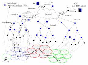
Figure 4. MN movement between networks in the global Internet requires mobility bindings to be updated with peers.
This is known as an inter-domain transition because the MN moves between different administrative regions. A home registration is sent to the HA and is classified as a global mobility signal. Because the BUs are sent to the true peer entities (CNs and HA) and propagate across different administrative regions. This is the exactly the functionality that MIPv6 provides.
Inside the visited domain, the MN moves from one subnet to another and these are called intra-domain transitions. An intra-domain transition involves the exchange of localised or regional mobility signals with the LMA and so is confined within a single administrative region. This BU is also known as a Regional Binding Update (RBU). The LMA is thus responsible for maintaining a forwarding or look up table that maps the MNs regional care-of address (RCoA) known by the HA and potentially CNs from the global mobility signals sent by the MN, to the current location of the MN i.e. local care-of address (LCoA) within the visited domain that the regional mobility signals provide. In effect it is acting as a local HA within this foreign domain. LMM implies not changing the address the HA and CNs use to reach the MN for any host movement within the visited domain. By moving the MM to the LMA so that it is closer to the MN, the MM process is dictated by the topological size of the administrative domain as opposed to the variable number of hops(represented as backbone round trip time in Figure 5 ) between the HA and MN across the wide expanse of the Internet.
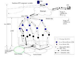
Figure 5. Introbuction of LMA for MN reduces the number of mobility bindings to the HA when mobility is rescricted to the foreign domain
LMM alone does not guarantee the end-to-end delay constraints of real time traffic are satisfied. However it is a prerequisite for reaching the goal of seamless mobility across the Internet.
There have been attempts to extend MIPv6 or proposals of new MM protocols that can be used for both intra-domain as well as inter-domain mobility. However it makes sense to separate the two mobility functions due to the following benefits:
There have been many LMM proposals suggested in light of the fact that MIPv6 has not been deployed commercially yet. In order to evaluate these Pagtzis et. el. have formally submitted an IETF draft on Local Mobility Management. The major requirements of interest are:
robust so that no single points of failure or routing loops occur
minimise the effect of triangular routing that is caused by introducing LMM
no additional functionality required over base MIPv6
incremental deployment
no increase in signalling messages to HA and CNs over base MIPv6
no increase in latency, packet loss, service disruption over base MIPv6
LMM complexity scales at most linearly with size of domain and MN number
Resilience to topological change
minimal manual configuration
no disruption to core IP routing outside of an administrative domain
Traditionally LMM protocols have been categorised as tunnelling or routing schemes. The routing schemes use conventional IP routing for redirection of the MNs CoA to its current location. The lookup tables are distributed amongst all mobility agents in the management domain. Examples of routing schemes are Handoff-Aware Wireless Access Internet Infrastructure (HAWAII) and Cellular IP. Tunnel-based schemes use LMAs for registration and tunnel packets to the MN with few agents having knowledge of the nodes location. HMIPv6 and regional registration extension for MIP are examples of tunnel based schemes.
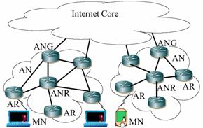
Eardley et. el. disagree with this traditional classification as it does not in their view offer any useful information on the performance of the protocol [44]. In their view these protocols should be classified based on their scalability, in particular terminal scalability, throughput scalability and geographical scalability. They state that terminal scalability is the ability for many wireless devices (potentially in the millions) to be accessible in the one access network (AN) is really just a problem of addressing. Given a proper address allocation procedure they do not think this should be a problem. In their opinion this excludes auto configuration as the MN has no way of knowing which addresses are already in use. Geographic scalability is the ability to service small home networks all the way up to a global network and throughput scalability would require flexible network topologies with many access network gateways (ANG) as shown in Figure 4.3. Support for arbitrary topologies allows operators the freedom to deploy the network with the required resilience allowing multiple paths to avoid congestion. Multiple access network gateway (ANG)s are necessary for throughput scalability and robustness. They state that seamless 41 handovers (handover management) does not need to be scalable. I disagree as the future of wireless Internet will most certainly be a multimedia rich experience so the signalling to local ARs to effect fast handovers will be crucial and dare I say all MNs will need this although perhaps not all the time and not altogether at once. They agree with Chiussi et. el. when it comes to criticising Cellular IP for been unscalable since the packets always travel the same path due to the strict hierarchy, so there is no provision for multiple ANGs. The surprising thing is that they also say that HMIPv6 if used in a hierarchical fashion will be no different from a performance point of view. The example used of mobile to mobile communication in the same access domain that can be very large, in the worst case may need to be established via the ANG is simply incorrect because in HMIPv6 route optimisation can be used to have the two nodes communicating directly rather than via the LMA if privacy is of no importance. So there should not be a need for a hierarchy of MAP registrations. This is also stated in the HMIPv6 draft [45, 20] too, where it is acknowledged a hierarchy of map bindings would degrade performance.
Hierarchical Mobile IPv6 (HMIPv6)
4.1 Hierarchical Mobile IPv6
HMIPv6 is simple in concept because it literally places the role of the HA into the LMA and referred to as a MAP [45]. The intra-domain transitions are defined as movements within the MAP domain. A MAP domain is delineated by the ARs that forward the same MAP option inside a router advertisement. The MN detects the presence of a MAP from the RAs MAP options. The MN chooses the best map according to its own policy if there were more than one and perform global registrations for the first time only to the CNs and HA. While it continues to detect the same MAP option at every handover it will only need to send a regional update that is a BU to the MAP. If it does not detect the same MAP but another MAP is advertised it can bind with the new one. If no other MAPs are advertised then it reverts back to MIPv6. Either way whenever the MN leaves a MAP domain it will have to update the global mobility bindings. The following is a list of advantages in deploying HMIPv6 as an LMM solution [45].
While the advantages are numerous there are also many disadvantages. The major ones would have to be the non-optimal routing, MAP discovery mechanism and recovery from MAP failures and poor MAP selection algorithm. The non-optimal routing forces a single point of failure and so does not satisfy the geographic scalability requirement discussed in Chapter 4. The default MAP selection procedure will select the same MAP for all MNs at ARs that are the same distance from the farthest MAP which would be the MAPs at or close to the gateways of an administrative domain. Thus the MAP will be a bottleneck. The HMIPv6 draft notes that the use of the preference value may be able to control this to some degree, so for overloaded MAPs they decrease their preference value. However this will simply move the problem to another MAP and becomes the classic routing problem of flutter where the congestion hotspot just moves around. There needs to be a domain wide load balancing scheme so that the MAP boundaries for each MAP can be adjusted at the same time as their preference values and in coordination with other MAPs.
MAP discovery by default is a manual process because the MAPs and ARs have to be configured before deployment. The configuration involves enabling which interface in the MAP and/or AR should send or forward the MAP option on, and the truly paranoid can turn off route optimisation altogether by sacrificing efficiency hence control the size of the MAP domain. For large administrative networks this involves a lot of manual work. While there exists an automatic method to propagate the boundaries of the MAP domain so routers know which interface to forward MAP options on [45, 17], the actual determination of the MAP boundary remains a manual process.
Can be very high in overhead with up to two sets of tunnel headers in both directions if the following conditions are met.
There will always be one tunnel since the MAP has to keep the original packet intact and so a tunnel from the MAP to MN exists with tunnel entry of MAPs global address and exit point of MNs LCoA. While it is possible to eliminate even this tunnel by route optimising all the way to the MN, so the CN knows about the LCoA too, this defeats the purpose of HMIPv6. This mode of communication is only valid Malicious nodes can use any source address and a non-ingress filtering router will forward them even when they are not topologically correct for very brief communication sessions where the MN is not likely to handover yet.
The MAP selection algorithm also needs to be much more adaptable than just a choose the farthest MAP algorithm. Further work has been proposed in this area and is presented in Section 4.3.
Fast Handovers in HMIPv6
Fast Handovers in HMIPv6 [46] aims to combine both HMIPv6 and FMIP to gain the benefit of HMIPv6s reduced signalling and registration times as well as shorter rendezvous time that FMIP buys. The argument goes that simply integrating the two protocols does not always reap the maximum benefit because:
To overcome these problems they proposed to replace the PAR with MAP. They say that their solution cannot work with non anticipated fast handover. However I say that it is possible if you set up the ingress filtering rule at NAR with all the MAPs in the domain instead of just the neighbouring PARs. This requires more coordination but certainly not as much as when compared to the amount of L2 support and coordination between APs and ARs required by anticipated handovers.
Local Mobility Agent Selection Algorithms
For micromobility it is very important how the MAP is chosen as it determines the latency and frequency of inter-domain handovers. This in turn depends on the mobility of the MN. HMIPv6 allows nodes to select the MAPs themselves. This is a two edged sword, because on the one hand, the MN knows what its requirements are so it can select the best MAP from its perspective. On the other hand any global scheme that tries to enforce which set of MNs are served by which MAPs have a hard time of enforcing this, since the MN is allowed to register with any MAP. While the MAP is at liberty to reject any BUs, this trial and error process will take a while before the MN has bound with the preferredMAP especially when many MAPs are available for popular sites.
Hop-by-Hop-Based LMA selection proposed in [47] has better MAP discovery mechanism than HMIPv6 because it actually involves a form of pinging to discover the LMAs rather than requiring ARs to forward them. But it still finds the farthest MAP so assuming high mobility in visited domain just like HMIPv6. Their protocol satisfied all the LMM requirements [48] mentioned in [41]. The explanation of the recovery mechanism was rather brief no more than a sentence in each reference and was to the effect of using source routing to see if it can still get a probe response from the registered (furthest LMA). If it does not then it should use the stored responses to choose the next furthest to register with. If all that fails then restart probe discovery. This mechanism is slow if inter-domain transitions are frequent as it backtracks through the list of LMAs in previously visited domains. The RFC has expired as of June 2003 so perhaps the authors do not think it is worthwhile in pursuing further.
The same group has proposed another LMM solution called Mobile Controlled Movement Tracking LMA Selection [49, 50]. It is similar in strategy to the MPLSbased mobility [8] because it also selects a close (in terms of number of hops) LMA to reduce signalling delay and yet far enough to cover the movement of the MN to reduce frequency of global handovers.
As mentioned before the rate of mobility is an important factor when deciding which MAP to register with. Kawano et. el. in [51] have taken this one step further and created a MAP selection algorithm that classifies the nodes mobility based on its dwell time in a MAP domain and chooses a MAP to match . In their performance evaluation of their proposed method for the network configuration as shown in Figure 4.4, there are only 2 types of nodes fast and slow. The threshold at which a MN is considered fast is 20km/h for their experiment. The MN does not choose the MAP but rather UA (User Agent) situated at the access router (AR) as shown in Figure 4.5. Whenever a node sends a BU it is the AR that intercepts this BU and the UA is instantiated to look at the Selection Table (ST).
The ST contains some simple entries that determine which MAP to register with for that particular speed profile. The STs are most likely precomputed and placed in each AR in such a manner as to effect a distributed and equal load across all MAPs in the administrative domain. The AR then sends a BU to the corresponding MAP on behalf of the MN. The details of who the BU was originally addressed to and the mechanism of proxy BU requests are not stated in the article.
Their simulation experiment was conducted in a network with a hierarchy of an m-ary tree. i.e. 1x16x16x4 (The root or core router of the domain was connected to the sixteen MAPs designated simply as higher MAPs and each higher MAP had 16 MAPs below them designated as lower MAPs and each lower MAP had 4 ARs). The output parameters used to judge performance were the number of BUs and also the mean number of MNs managed per MAP. They compared their method against three schemes; one that always chose the higher MAP; one that always chose the lower MAP; a random MAP. Their method consistently performed better than the other three schemes where relevant and they also proved that their for details of the algorithm please consult [51] protocol is independent of the network topology to some extent as they tried it on a different topology (1x4x16x16 m-ary tree) too. Most importantly they varied the actual threshold parameter from 0 to 50 km/hr in increments of 10 and were able to show that for threshold settings above 10km/hr their method also outperformed the other three. Thus the speed threshold need not be accurate just a reasonable enough estimate, since the algorithm is robust enough to tolerate a wide error margin. The only problems with these results are that they gave no mention of the simulation model used. The protocol at face value looks like it has some merit however there will usually be more than two levels of hierarchy in large 3G networks so it would be interesting to test if it could handle say up to six or seven hierarchies. Another difficult problem would be the creation and distribution of these ST tables as manually pre-computing them and distributing is not scalable for large access networks. The only feasible alternative is for extra signalling to be introduced to exchange the load information on each MAP and calculate the ST separately at each UA at regular intervals.
Other Micromobility Protocols
Cellular IP and HAWAII have both been mentioned previously. Cellular IP is a mechanism that modifies base IPv6 forwarding in such a way so as to allow upstream data packets sent by the MNs to create forwarding entries in the opposite direction. This in effect is very similar to the way Ethernet switches work. The MNs register the Access Network Gateways (ANGs) address as their CoA. The downstream packets which will be extracted by the ANG and have the HoA as source and flow through the modified routers and use these recorded routes in reverse to reach the MNs current location. Thus the whole access network becomes a flat host based routing scheme and so is not considered scalable by many. Kim and Song in [xx] suggest using a periodic binding update method to reduce the number of unnecessary binding updates and hence reduce signalling load on network and processing delay for handover when a node is highly mobile or moves back and forth frequently between a few links. Their method works by choosing a value for the configurable time period t based on the mobility of the node. At every t seconds the node will detect if the current network prefix as advertised by the router is different from its care of address. Only if it is different will it perform a layer 3 handover and send a binding update to the HA and CN. Otherwise it will reset the timer. The routers on the foreign links will have to be able to buffer the packets whilst the MN moves to different foreign link without notifying CN and HA. After MN registers new location with CN and/or HA then it is able to request previous foreign link to forward buffered packets to itself. Their M/M/n queueing analysis found that as long as the probability of binding at every t seconds is less than 70% then there is an improvement in the processing delay as compared to plain MIPv6.
In [yy] the authors claim that their proposed protocol Cellular Mobile IPv6 (CMIPv6) can reduce L3 handover by using foreign home agent (FHA)s to track location of the MN that according to the authors is better than HMIPv6 for cellular networks. The FHA appears to spy on the link for BUs and will store some location information into a Location Table (LT). When the MN moves and sends a BU to its peers, the FHA is able to determine the NCoA of the MN from the BU that passes approx. 112km/hr in their analysis a modified router through it to the peer node. Thus it is able to set a temporary forwarding from the PCoA to the NCoA for any packets in transit before the BU arrives at the MNs peers. This is similar to Cellular IP except this modifies normal packet processing during handover only. It does improve handover latency over MIPv6. CMIPv6 is most effective when the rendezvous time is small in comparison to registration time as communications resumes just after the BU is sent. Their evidence for this is that the Linux MIPv6 implementation takes only 200ms for acquiring a CoA. This is an exaggeration because it does not seem to take DAD into account, unless their link-layer technology does not require DAD.
There are also LMM schemes that borrow successful protocols from different domains such as Multi Protocol Label Switching (MPLS) from Traffic Engineering (TE) and a multicast-based one called Multicast-based Micro Mobility. Basically both of these protocols borrow from the signalling primitives already available and which have proven to be effective for their application areas. For MPLS the argument is that MPLS is actually more efficient than IP itself since MPLS labels are used for forwarding purposes. It should be more scalable since MPLS can handle thousands of labelled paths and has proved more than capable. For the multicastbased method their argument was that the multicast tree is perfect for forwarding to the MNs current location. The route will always be route optimised since that is a property of the multicast algorithm. It uses multicast group joins and leaves to notify the network of where the MN is exactly. Thus it is rather similar to Cellular IP in that the routing information is distributed in many nodes but this is much more efficient because the author has used some kind of algorithm to aggregate the state information so that it occupies less memory.
/*BEVEZETŐ SZVEG*/
Performance Evaluation of Mobile Ipv6 Enhancements
IPv6Suite Simulation Framevork
Ipv6Suite Deviations from MIPv6 RFC
Simulation Scenarios
Access Router Localised Handover Extensions
Previous Care-of Address Forwarding
HMIPv6
Discussion of Results
Access Router Localised Handover Extensions
Round Trip Time Irregularities
Optimistic Duplicate Address Detection
Fast Solicited Router Advertisements
Fast RA Beacons
L2 Trigger
RA Localised Extensions Combined
Previous Care of Address Forvarding
Hierarchical Mobile IPv6
Conclusions and Recomendations for Future Work
Conclusions
Recomendations for Future Work
References
|
Politica de confidentialitate | Termeni si conditii de utilizare |

Vizualizari: 4705
Importanta: ![]()
Termeni si conditii de utilizare | Contact
© SCRIGROUP 2025 . All rights reserved