| CATEGORII DOCUMENTE |
| Bulgara | Ceha slovaca | Croata | Engleza | Estona | Finlandeza | Franceza |
| Germana | Italiana | Letona | Lituaniana | Maghiara | Olandeza | Poloneza |
| Sarba | Slovena | Spaniola | Suedeza | Turca | Ucraineana |
WATER SUPPLY AND DISTRIBUTION SYSTEMS
CREDIT HOURS . . . . . . . . . . . 2
TEXT ASSIGNMENT . . . . . . . . . Attached memorandum.
MATERIALS REQUIRED . . . . . . . . None.
LESSON OBJECTIVE . . . . . . . . . Upon completion of this lesson on water
supply you should be able to accomplish the
following in the indicated topic areas.
--------------------------------------------------------------------------------
1. Corps of Engineers responsibilities. Define the Corps of Engineers involvement in the supply of water and the various levels of responsibility.
2. Definitions and formulas. State the common terms used in water supply along with their definitions. Give the formulas and factors used in determining flow, pressure, head, and head loss.
3. Distribution systems. Describe the three basic types of distribution systems to include open channels, pipes, storage facilities, treatment, and distribution.
4. Water requirements. Determine water requirements for the various types of installations and activities.
5. Pipeline design. Explain the sequence and considerations in pipeline design to include reconnaissance, surveys, layout, availability, and simple and compound systems.
6. Operation and maintenance of systems. State the essential points in operation and maintenance of water supply and distribution systems.
ATTACHED MEMORANDUM
4-1. INTRODUCTION
An adequate supply of palatable, safe water is an essential prerequi-site for the health, general welfare, combat efficiency, and morale of troops. The supplying of this water is one of the primary functions of the Corps of Engineers. Hence, this lesson is for the engineer officer confronted with the task of providing potable water for small and medium semi-permanent military installations. It contains minimum information required for designing a stationary system to provide safe water.
4-2. PLANNING, DESIGN, AND
CONSTRUCTION
a. Phases. The work of planning, designing, and constructing utilities is divided into the following phases:
(1) Preliminary investigation.
(2) Engineering layout and design.
(3) Scheduling construction.
(4) Supervising construction.
b. Planning guides. Planning of utilities for a project is based on Department of the
Army general policy and is guided by the theater construction policy and the job directive.
(1) Theater construction policy is issued by headquarters to establish uniform construction practice and to conserve labor, equipment, and materials. The policy sets maxi-mum standards for initial, temporary, and semi-permanent construction, and recommends typical designs.
(2) Job directives are issued by higher headquarters to initiate the project and define the construction by establishing the following:
(a) Location of construction site by limiting coordinates with reference to a known point, aerial photograph, or map.
(b) Enumeration of major facilities and basic requirements.
(c) Priorities of construc-tion for the various facilities.
(d) Required dates of usable completion.
c. Responsibilities of the officer in charge. To carry out the various phases of work successfully, the of-ficer in charge of installing utili-ties for a camp, hospital, or other installation must plan and perform the following tasks in their proper sequence.
(1) Site reconnaissance. A perso-nal reconnaissance of the site is made to obtain information on its physical characteristics and other factors affecting the proposed construction.
(2) Preliminary field investi-gation. Plane and topographic surveys, soil borings, stream-flow measure-ments, and the like are made for engi-neer planning and designs as required.
(3) Inventory of available resources. The officer in charge inventories the materials, labor, equipment, and other available
construction facilities and takes steps to secure all items required for the completion of the project on schedule.
(4) Engineering designs. Layouts and designs are prepared and used as a basis for constructing all utilities installations.
(5) Quantity survey. The lists of materials that must be ordered or requisitioned and the estimates of the principal items of
work, such as excavations to be made or concrete to be placed, are taken from the engineering plans and work sheets.
(6) Priorities and stages of construction. Priorities establish the order in which construction of the various individual utilities must be completed. Stage construction, the
procedure followed when a project is completed either by units or by levels of improvement, permits early use of items of high priority, such as water and electricity.
(7) Forecast of working conditions. Working conditions, including climatic conditions, interference due to use of the project
before completion, and effects of enemy action are estimated before construction begins.
(8) Schedule of operations. Construction operations are scheduled to show the sequence of operations and the time allotted for each work item. Sequence is the order in which operations must begin. Work items are specific tasks for which the work output of men and equipment is known or can be estimated.
(9) Supervision of construction. Supervision of construction requires the control, coordination, and adjustment of construction schedules and operations to insure that the work is done according to plans in an efficient, expeditious, and safe way.
(10) Accident prevention. All hazards to safety observed during preliminary investigations, construc-tion, and operation of utilities should be eliminated or a positive control provided.
(11) Maps. As construction progresses, maps showing the location of all utilities and their important component parts are prepared for use in future operations and repairs.
4-3. COMMONLY USED TERMS IN WATER SUPPLY AND DISTRIBUTION
a. Discharge. The rate of flow or volume of water passing a given point in a conduit or
channel in a given time is discharge (Q). It is usually measured in cubic feet per second (cfs), gallons per minute (gpm), or gallons per day (gpd). Discharge is expressed by the
basic formula: Q = AV
Where: Q = discharge in cfs.
A = cross-sectional area of conduit or channel in square feet,
V = average velocity in feet per second (fps).
b. Atmospheric pressure. Atmospheric pressure varies slightly from time to time depending on weather. It also varies with elevation above or below sea level. Except in computations requiring extreme accuracy it is assumed to be 14.7 pounds per square inch (psi).
c. Pressure. Pressure is force exerted on an area. It may be expressed in various units, such as pounds per square inch, pounds per square foot, or grams per square centimeter. A column of water 1 foot high exerts a pressure of 0.433 pound per square inch (psi) regardless of the diameter of the column.
d. Relationship of pressure and head. Pressures are expressed in pounds per square inch (psi) or in feet of water depth. The depth of water required to produce a given
pressure is termed head.
Example:
62.4 pounds per cu ft(weight of water)
--------------------------------------
144 sq in. (1 sq ft)
= 0.433 psi per ft of height or head.
144 sq in. (1 sq ft)
----------------------
62.4 pounds per cu ft
= 2.31 ft of height or head per psi.
In other words; a column of water 2.31 feet high exerts a pressure of 1 psi on its base. Conversely, 1 psi exerted on the base of a column of water will raise it 2.31 feet. Thus, to convert pressure in psi to head in feet, multiply by 2.31; and to convert head in feet to psi, multiply by 0.433.
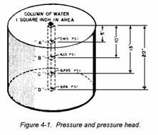
e. Difference in pressure. If the tank in figure 4-1 is full of water, the head of water at point A is 5 ft. The pressure exerted is 5 x 0.433, or 2.165 psi. Points B, C, and, D are calculated in the same way. The difference between unit pressures at any two points in a liquid at rest is found by first computing the unit pressure at each point and then sub-
tracting one value from the other. For
example, if one point is at a depth of 20 feet below, the surface of a body of water and the other point is at a depth of 30 feet below the surface, the intensities of pressures at the points are 8.36 psi (20 x 0.433) and 12.99 (30 x 0.433), respectively. The difference in pressure between the two points is 4.33 psi. This same rela-tionship applies to other liquid under pressure, whether it has a free sur-face or not, primarily because the intensity of pressure at every point on the surface of the liquid is the same. In other words all points in the same plane perpendicular to the verti-cal line of gravity have the same pressure exerted on them whether the overlying liquid is under pressure or not.
f. Absolute and gage pressures. Pressure intensities may be expressed with reference to either of two bases; absolute zero pressure such as exists in a complete vacuum; or atmospheric pressure, which at sea level averages 14.7 pounds per square inch (psi) above absolute zero pressures. Abso-lute pressures are used primarily with steam and are always positive. In water supply and distribution, however, it is more convenient to use atmospheric pressure as the base or
zero pressure. Pressures which use atmospheric pressure as the reference point are called gage pressures. Gage pressures above atmospheric pressure are positive; those below atmospheric pressure are negative and are written with a minus (--) sign. Accordingly, for example, 5 psi gage pressure is taken to equal 5.0 + 14.7, or 19.7 psi absolute pressure. Conversely, a gage pressure of--5 psi is equal to 14.7 -- 5.0, or 9.7 psi absolute pressure.
g. Relationship of gage and absolute pressures. The theoretical relationship between absolute pressure and gage pressure is illustrated in figure 4-2 which represents a water barometer. If it is assumed that the
space above the water in the tube consists of an absolute vacuum, with no pressure from vapor, the surface x-x of the water in the tube will be 33.9 feet above the free surface d-d, which is exposed to atmospheric pres-sure. If a certain section y-y is 14.0 feet below x-x and 19.9 feet above d-d, for example, the absolute pressure is equal to the weight of the over-lying water, which is 14.0 feet. The gage pressure at the line y-y is nega-tive, however, because this section is above the level d-d at which there is full atmospheric pressure. The amount of this negative pressure is equal to the height of the section y-y above the free surface d-d, or 19.9 feet. Therefore, the gage pressure is equal to the negative head of the volume of water, or
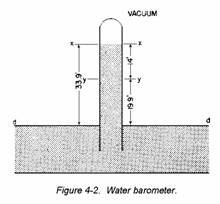
-19.9 feet. As indicated in c above--19.9 times 0.433 equals -8.6 psi.
h. Head losses. To start and maintain a flow of water in either open channels or pipes, energy is required, the amount of which is measured and expressed by loss of head. These losses are termed velocity-head and friction-head losses.
(1) Velocity-head loss is equal to the energy required to overcome inertia in starting the flow or increasing its velocity. In a
gravity system this loss is evaluated by the formula:
V22 - V12
h = ---------, in which
2g
V1 = initial velocity in feet per
second final velocity in feet
per second
V2 = acceleration of gravity = 32.2
feet per second per second
g = acceleration of gravity = 32.2
feet per second
h = head
Example: A stream of water is flowing
through a channel, whose cross section is a semicircle, at a velocity, V, of 15 feet per second. The head required to overcome the inertia and increase the velocity to 30 feet per second, assuming no loss due to friction, would be:
V22 - V12 302 - 152
h = ---------- = ---------
2g 2 (32.2)
675
= ---- = 10.5 feet
64.4
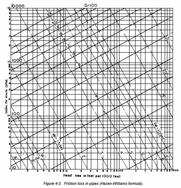
(2) Friction-head loss is equal to the energy required to overcome the friction between the surface of the channel of pipe and the moving water. Many formulas have been designed to determine the friction loss. The most common formula used in American practice for calculating friction-head loss in pipes is the Hazen-Williams formula:
V = 1.318 CR063 S054, in which
V = velocity of water in ft per second
C = coefficient of friction (120 is
recommended for clean new pipe; 60
for old tuberculated pipe; 100 is
recommended for design),
S = loss of head per foot of pipe,
R = hydraulic radius (by definition, the hydraulic radius is the cross-sectional area divided by the wetted perimeter or one-half the inside radius of a completely filled pipe of circular cross section).
Example: Find the head required to overcome the friction per foot of pipe if the water is flowing at a velocity of 25 feet per second through a pipe whose inside diameter is 2 feet and coefficient of friction is 100.
V = 1.318 CR0.63 S0.54
V1.85 1
S = ------------ X ---------
C1.85 R1.17 1.3181.85
log S = 1.85 log V - 1.85 log C - 1.17 log
R - 1.85 log 1.318
log S = 1.85 log 25 - 1.85 log 100 - 1.17 2/4
- 1.85 log 1.318
log S = 1.85 (1.398) - 1.85 (2) - 1.17
(-1.699) - 1.85 (0.12)
log S = 2.58 - 3.7 - 1.17 (9.699 - 10) - 1.85 (0.12)
log S = 2.58 - 3.7 - 11.35 + 11.7 - 0.22
log S = 14.28 - 15.27 = -0.99
log S = 1 log .99
1
log S = -- = 0.10 ft head loss per ft
99
of pipe
(3) When water is received from a source which is higher than the point of distribution, the available head created by a difference in height may be used to overcome friction in pipe and also maintain a given head at the point of distribution. For exam-ple, if a source of water was located 18 feet above the point of distribu-tion and if the head required to pro-vide adequate pressure at this point was 5 feet, 13 feet of head is avail-able to take up the friction-head loss. Friction-head loss as calcula-ted by the Hazen-Williams formula is expressed in feet of water. The head loss may always be overcome by raising the water source an amount equal to the height of the loss in feet of head in the pipe.
(4) Figure 4-3 is a chart from which you may read directly the friction-head loss per 1,000 feet of various size pipe (using C = 100), when you know either the quantity of flow in gallons per minute (gpm) or the velocity of flow in feet per second (fps). For example, for a flow of 300 gallons per minute in a 4-inch pipe, with C = 100, the friction head is 80 feet per 1,000 ft of pipe. This is determined by finding the 300-gpm line on the vertical scale, following this line across horizon-tally to its intersection with the diagonal line representing 4-inch pipe. The friction-head loss, 80 feet, may be read on the horizontal scale directly below the point of intersection. If the velocity and pipe size are known, the head loss in feet can be read on the horizontal scale directly below the point of intersection of the velocity lines and pipe-size lines. For example, a velocity of 7.1 fps in a 4-inch pipe, with C = 100, would produce a friction-head loss of 80 feet in 1,000 feet of pipe. Interme-diate values and measurements not actually shown by lines on the chart are determined by interpolation.
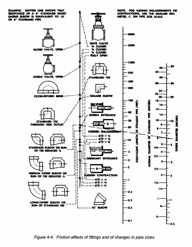
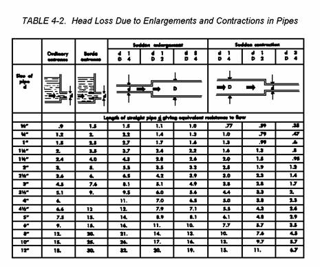
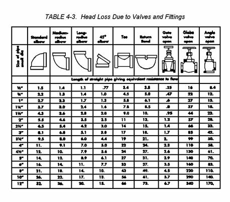
(5) Other head losses are caused by changes in pipe sizes and by pipe fittings, such as bends, tees, and crosses. Such losses are included in all calculations by substituting the length of straight pipe which would produce an equivalent amount of head loss (fig 4-4).
i. Static head is the pressure occurring when all valves are closed and the water is not flowing. The amount of pressure during flow is obtained by subtracting velocity, friction, and other head losses from the static head.
j. Suction head is the term used to indicate negative gage pressures. It is measured at the inlet flange of pumps set above the elevation of the reservoir, lake, or stream from which water is drawn. Flow to the pump in such cases is caused only by the
atmospheric pressure on the reservoir surface. You have learned that atmospheric pressure is 14.7 psi and that this is equivalent to a head of 33.9 feet (14.7 x 2.31). Theoreti-
cally, water can be 'sucked up' (in reality, pushed up) 33.9 feet to the pump, but because of velocity, friction, and other losses in the pump and intake pipe, satisfactory operation cannot be maintained in excess of about 20 feet.
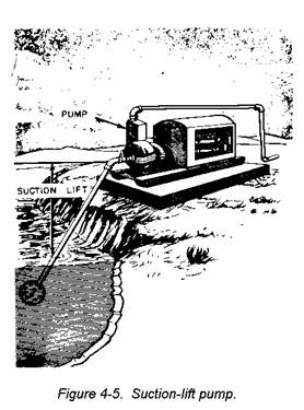
k. Suction lift is the vertical distance in feet from the level of the water source to the pump (fig 4-5).
l. Velocity is the speed of flow of water, usually expressed in fps.
m. Quantity is the amount of flow of water expressed in cubic feet per second (cfs) or in gpm.
4-4. OPEN CHANNELS
a. Surface-velocity method. To determine discharge in open channels by the surface-velocity method, proceed as follows:
(1) Find the cross-sectional area of the stream in square feet by multiplying the average stream depth by the width.
(2) Find the average velocity of the stream. To do this, observe the time required for a floating object to travel a given distance, and compute the surface velocity in fps. Assume the average velocity is three-quarters of the surface velocity.
(3) Compute the discharge (Q) using the discharge formula, Q = AV.
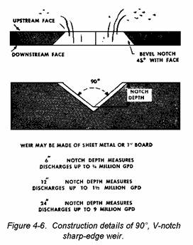
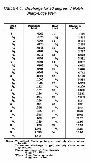
b. Weir method. The 90-degree V-notch sharp-edge weir is a convenient and accurate way to measure flows from 5,000 to 9,000,000 gpd. Weirs are eas-ily improvised in the field and read-ily transported to the point of use.
(1) Construction. Construction details for the 90-degree V-notch sharp-edge weir are shown in figure 4-6.
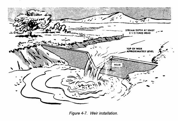
(2) Installation. Install the weir as part of a dam so the water backs up at least
two and one-half times deeper than the expected head on the weir (fig 4-7). The top edge of the weir should be approximately level.
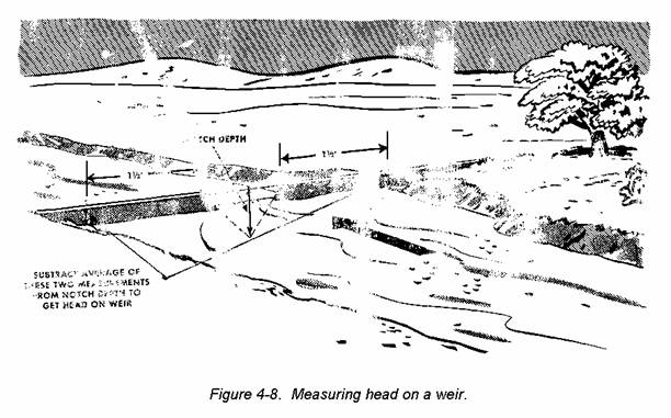
(3) Head measurement.
(a) Measure the distance from top of weir to water surface on the upstream face at two points, each point about 1 feet from the weir notch (fig 4-8).
(b) Average these two measurements.
(c) Subtract the average of the two measurements from the notch depth. This gives the head on the weir.
(4) Discharge. From the head on the weir, determine the discharge (table 4-1).
c. Manning's formula method.
(1) The discharge of an open channel may be determined by computation using Manning's formula.
1.486 r2/3 √s
V = -------------
n
Where: V = average velocity in fps.
r = hydraulic radius (the
cross sectional area in square feet divided by the wetted perimeter in feet).
s = slope of channel in feet
per foot of channel
length.
n = coefficient of roughness
which varies for different
channel surfaces as follows:
n = .012 for smooth planed
timber or smooth ce-
ment mortar.
n = .013 for smooth brick-
work, smooth concrete,
or vitrified tile.
n = .014 for average con-
crete.
n = .015 for rough brick-
work.
n = .020 for rubble mason-
ry or canals in firm
ground.
n = .025 for canals or
rivers with sides in
good condition.
n = .030 for canals or
rivers with some
stones or weeds.
n = 0.50 for rivers with
channels obstructed by
stones and weeds.
(2) After finding the average velocity by Manning's formula, compute the discharge (Q) from the discharge formula, Q = AV.
4-5. PIPES
a. General. Flow of water in a given length of pipe depends on pipe size, a friction factor C indicative of the interior roughness of the pipe, and the difference in pressure head (head loss) between the two ends of the pipe.
b. Finding discharge.
(1) Discharge may be found from the nomograph shown in figure 4-9. To determine
discharge using the figure, the pipe size, condition of pipe interior, and the loss of head in feet per 1,000 feet of pipe must be known. Loss of head in feet per 1,000 feet of pipe is found by dividing the difference in pressure head in feet at the two ends of the pipe by the apparent pipe length in thousands of feet. Difference in pressure head is caused by difference in elevation or by a pump. For pipe without obstructions such as valves, bends, fittings, and enlargements or contractions, the apparent length equals the measured length. For pipe with obstructions, the apparent length equals the measured length plus the equivalent length of each obstruction (Tables 4-2 and 4-3).
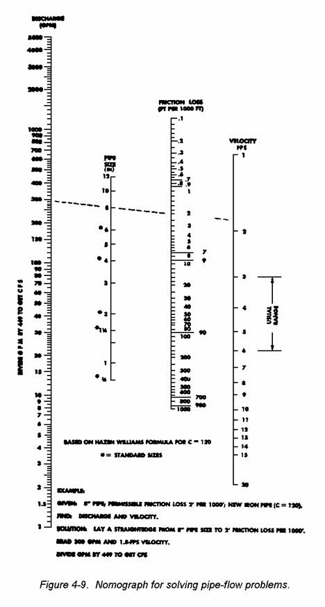
(2) Normally, the effect of obstructions is small and may be disregarded, the apparent length being taken as the measured length. However, in short systems having many obstruc-tions, the effect of obstructions should be included in the apparent length.
4-6. SUPPLY LINES AND DISTRIBUTION SYSTEMS
a. Function. Supply lines carry water from the gravity intake, pumping station, treatment plant, reservoir, or storage tank to the distribution system which conveys it to the outlet.
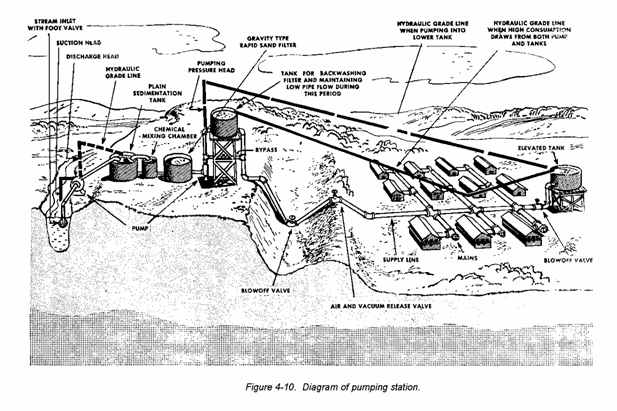
(1) An ample supply of safe water for drinking, cooking, and bathing is essential for every Army installation. It is desirable that the water be clean, colorless, and odor-less, and that the system be capable of deli-vering it without interruption. No water from natural sources is chem-ically pure, but safe water has only limited amounts of harmful chemicals and no pathogenic bacteria. A water-supply system includes a source, in-takes, convey-ances, facilities for storage and/or treatment, and a dis-tribution system consisting of mains, submains, valves, branch lines, and service lines (see fig 4-10).
(2) Sources of water include natu-ral or impounding reservoirs, streams, wells, catch basins for rain, and bodies of salt water.
(3) Intakes are used as a means of obtaining water from its source. This may be done by pump, gravity flow, or by a combination of pump and gravity flow. Screens are used on intakes at surface sources to keep fish and floating debris out of the water system. In wells they are used to keep out sand.
(4) If the source is distant from the point of consumption, aqueducts, pipelines, or open channels are needed to convey the water. In rare instances mobile water-transport units must be used.
(5) In all military and most civi-lian systems, a treatment plant is required. Normally, chlorine is used in these plants as the disinfecting agent, but, in some cases, oxygen or iodine may be used.
b. Description.
(1) Basic systems. There are three basic types of water supply and distribution systems.
(a) Gravity. Storage reser-voirs of gravity distribution systems are usually located high enough to develop required pressure and flow. Storage tanks may sometimes be gravity filled from springs located at a higher elevation than the water level of the tanks, but are usually filled with pumps. Because of their relative elevation, the storage tanks eliminate need for continuous pumping.
(b) Direct pumping. Direct pumping systems usually have no ele-vated storage tanks and water must be pumped into the distribution system from ground storage reservoirs, wells, or the distribution system of a muni-cipality or other source, at a rate depending on demand. Therefore, con-tinuous pump operation is necessary.
(c) Combination of gravity and pumping. A combination system can be used, with the primary mains being supplied from the two sources mention-ed above.
(2) Pipes.
(a) Classification. The net-work of pipes should be arranged so large primary mains feed smaller secondary pipes. Service pipes carry water from the main to the buildings. Mains carry water from the source to the service pipes.
(b) Arrangement. Distribution systems may be arranged as a dead-end system or as a loop system. In dead-end systems, the flow is not continu-ous. In loop systems, the ends of all mains are connected so water circu-lates continuously, while it is being drawn from any point on the loop.
c. Design. The design of a distribution system is based on the known requirements and on the physical data obtained from reconnaissance, surveys, and maps.
4-7. REQUIREMENTS
a. Demand. The distribution system
should deliver enough water to meet the
maximum rate of demand (peak demand) for drinking, cooking, personal hygiene, and other authorized uses.
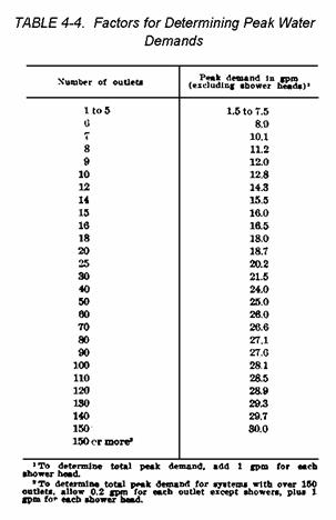
(1) Peak demand. The size of the distribution main serving an area depends on the total peak water demand for that area. Service connections and mains must be large enough to deliver the total peak demand under the available pressure. The factors for
determining peak demand, in gpm, for any area serviced by a single main are given in table 4-4.
(2) Fire protection. Normally, distribution systems are not constructed large enough to supply the large demand required for fire protection. It is best to provide ground storage tanks or sumps at strategic points so all buildings can be reached with not over 1,000 feet of hose. Water is pumped
from the tanks or sumps by a fire pumper or skid-mounted pump.
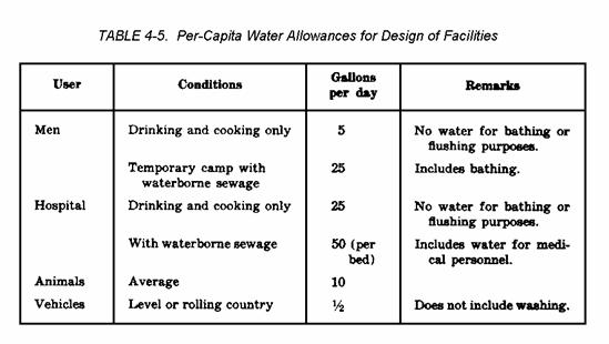
(3) Water-consumption data. In planning and designing water-supply and distribution systems, the type of project to be supplied and its size, based on the expected population, are the primary considerations. If consumption data are known, basic requirements can be calculated from table 4-5. Water-consumption data are also necessary for development of the source and storage facilities, design of the distribution system and pumping plants, and selection and design of treatment plants. Storage facilities should be designed to hold at least 50 percent of 1 day's water requirements.
(a) Areas without sewers. In Army installations without sewers, the basic per capita consumption is 5 gallons per day.
(b) Industrial areas. In industrial areas, requirements average about 100,000 gallons per acre per day.
(c) Family quarters. Each resident of permanent Army instal-lations requires a minimum of 60 gallons per day, including an allow-ance for waterborne sewage. In the average family-quarters area, minimum consumption occurs on Sundays and peak consumpton on Mondays. The highest demand for water occurs from 0700 to 0900 and from 1700 to 1930. Minimum demand occurs at 0400 hours.
(d) Calculating consumption. When calculating consumption require-ments for systems such as company bathhouses or hospital utility build-ings, the number of water outlets and shower heads should be considered. The peak water demand for any area or building served by a distribution main is determined by allowing 1 gallon per minute for each shower head, and 1.5 gallons per minute for each of the other outlets. Theoretically, at an allowance of 1.5 gallons per minute per outlet, a peak demand would equal outlets times allowance per outlet. But experience indicates that the greater the number of outlets, the lower the probability of their all being used simultaneously. Therefore, for design purposes, peak demands are reduced in a
ratio to the total number of outlets. The peak water demands for a given number of outlets (excluding shower heads) are contained in table 4-4. Service connections in buildings must be capable to supplying the peak demand. The size of distribution mains serving several buildings is determined by the total shower demand, plus the total demand of all other outlets. Service connections and mains should be large enough to
deliver the required flow under the available pressure.
b. Pressures.
(1) Working pressures for conveying water through mains vary with the permanency of the instal-lation and the equipment available. In the field, pressures from 20 to
70 psi are ordinarily satisfactory.
(2) Distribution lines should deliver peak water demands to areas served by individual mains with at least a 20-psi working pressure at the service connection. Working pressures above 100 psi increase the breakage and maintenance on fittings and fixtures and water hammer may occur at 100 psi. Excessive distribution pressures may be reduced by pressure reducers and pressure relief valves.
(3) Nomographs and similar scales are used for designing water-distribution systems. If any two factors in a nomograph are known, a straightedge placed across them, as in figure 4-9, indicates the unknown factor.
(4) Doubling the diameter of a pipe increases the cross-sectional area four times, and increases its capacity between six and seven times.
c. Friction losses. Friction losses in service connections and distribution mains are normally based on the use of iron or steel pipe, using a C coefficient of 120. If the installation is expected to be in use more than five years, the coefficient of 100 should be used.
4-8. SURVEYS AND MAPS
The need for surveys is established by reconnaissance, by the extent and accuracy of existing maps, and by data needed to complete designs. Topographic maps should be prepared to a horizontal scale of 1 inch equals 10 feet, with 1-foot contour intervals at
intakes, pump stations, and treatment plants. Allowable horizontal error in alinement and profile surveys is 1 in 5,000. Vertical levels are read to one-tenth foot on the ground or one-hundredth foot on bench marks, turning
points, and existing permanent struc-tures. If Government bench marks are not convenient, an arbitrary reference point must be estab-
lished. Locations and layouts of all pipelines and structures are plotted on profile sheets and topographic maps. Established pipeline profiles and hydraulic grade lines are plotted on profile and map sheets, or may be separate drawings.
4-9. TYPE AND SIZE OF PIPE
a. The design of mains and service pipes for theater of operations distribution systems is limited by the type and size of available pipe. Working pressures and other features of the supply and distribution system must be established by the designer to suit the characteristics of the available pipe and pumps.
b. Pipe is shipped overseas in a limited number of standard sizes and types. Interior plumbing and service pipes of steel or bitaminized fiber may be available in 3/4-, 1- 1 1/3 2-, 4-, 6-, and 8-inch sizes.
4-10. PIPELINE DESIGN
Pipeline design consists of determining one of the following factors when the other two are known: head, pipe size, and discharge.
a. Definitions.
(1) Available head. The available head is the head causing flow through a pipe. It may be obtained by gravity, by pumping, or by a combination of both.
(a) In a gravity system, the difference in elevation between the water surface at the inlet and at the outlet is the gravity head, and constitutes the entire available head.
(b) In a pumping system on flat terrain, the pump discharge head is the available head.
(c) In a pumping system on uneven terrain, the difference in elevation (gravity head) between the pump and the outlet of the pipeline must be included. Where the outlet is lower than the pump, the available head is the pump discharge head plus the gravity head. Where the outlet is higher, the available head is the pump discharge head minus the gravity head.
(2) Permissible head loss. The available head in feet divided by the length of pipeline in thousands of feet is the permissible head loss in feet per thousand feet. If the pipeline is short, the effect of fittings should be included.
(3) Economical velocity. To avoid excessive pump horsepower, usual flow velocities for pumping systems are between 3 and 6 fps. For gravity systems, velocities are limited only by the available head.
b. Simple pipelines. A simple pipeline is the same diameter throughout its length and does not have any branch lines. Simple pipelines may be designed by using the nomograph in figure 4-9.
c. Example.
Given: Gravity system; water surface at outlet 100 feet below water surface at inlet; required flow 500 gpm; length of line 16,000 feet; new iron pipe (friction factor C = 120).
Find: Pipe size.
Solution: permissible head loss is--
100
---- = 6.25 feet per 1,000 feet.
16
The nomograph (fig 4-9) shows an 8-inch pipe is satisfactory.
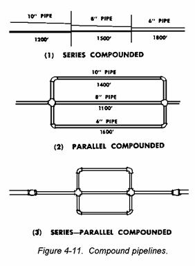
d. Compound pipeline. Compound pipelines (fig 4-11) may be a series compounded, parallel compounded, or series-parallel compounded. Different size pipes connected in series are series compounded. Pipes of the same size or of different sizes connected in parallel are parallel compounded. Parallel compounded lines connected to either simple or series compounded lines are series-parallel compounded. In solving problems involving compound pipelines, first reduce the compound pipeline to an equivalent simple pipe-
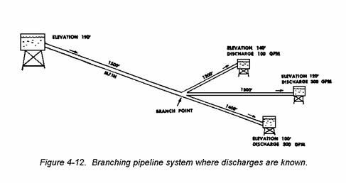
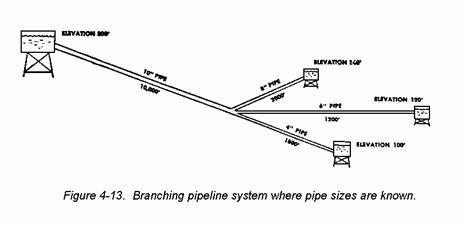
line. In other words, find the pipe of a given diameter which gives the same total head loss as the compound line. Flow problems are then solved as for the simple pipeline. Table 4-6 gives factors for converting a pipe length of a given size to an equivalent length of another size. Figure 4-12 shows a branching pipeline system where discharges are known,
and figure 4-13 shows a system where pipe sizes are known.
4-11. OPERATION AND MAINTENANCE
a. Importance of maintenance. Failure of water supply systems often is attributed to defective equipment when improper plant operation and maintenance by unqualified
personnel are the true causes. Pump operators must be familiar with the mechanical features and safe operation of their equipment; treatment-plant operators must understand the physical processes of water treatment and have some knowledge of the chemistry involved; and all operators must be
alert to detect and correct sources of trouble before they occur.
b. Pumps. Operation, maintenance, lubrication, and parts manuals are available for all standard types of depot-stocked equipment. In general, pump operation consists of pumping against the full head that gives the
highest pump efficiency; pump maintenance consists of lubrication, and eliminating air or
water leaks. Vapor or air locks reduce or stop the output and may cause pumps to overheat. The pressure gage on the pump outlet, which indicates line pressure, must be watched closely. Head loss due to a line opening or an increase in pressure caused by a stoppage or a closed valve is quickly indicated on the gage. The power unit must be fueled, lubricated, and provided with
cooling water. In freezing weather, precaution must be taken to prevent ice from bursting the equipment or causing stoppages. The pressure-release valve must be working properly in displacement-pump systems to prevent breakage due to increasing pump pressure caused by line shutoffs. Any increase beyond the normal maximum pressure should be counteracted immediately by reducing pump speed or stopping the pump entirely and opening the waste valve. The trouble then can be located and corrected.
c. Treatment plants. Plant operation and maintenance necessarily vary with the type of installation. Operating manuals for the mobile and portable purification units are useful in operating all systems, but in larger fixed installations each process must be studied carefully to determine the most efficient operating procedure. The physical processes and chemistry of purification are explained in TM 5-700.
(1) Rate of flow, length of the retention period, accumulation of sludge, and the amount of chemicals used in coagulation and disinfection must be checked closely.
(2) In freezing temperatures, adequate velocities must be maintained to prevent ice formation. In extremely cold climates, tanks and filters should be enclosed in a heated building.
d. Pipes and distribution systems. The pipe and distribution system should be patrolled regularly to de-tect leaks or unauthorized connections and to test the operation of valves. Sludge and organic growth which accu-mulate in low velocity line should be flushed out occasionally by increasing pressure during a low consumption pe-riod and then opening blowoff valves to obtain a maximum velocity of flow. Various types of mechanical cleaners are used to remove rust and other in-crustation. Such processing is usually not required for several years after the line is laid. Valves at branch or main intersections must be adjusted properly to equalize pressures and assure service to the ends of the line.
REVIEW EXERCISES
Note: The following exercises are study aids. The figures following each question refer to a paragraph containing information related to the question. Write your answer in the space provided below each question. When you have finished answering all the questions for this lesson, compare your answer with those given for this lesson in the back of this booklet. Review the lesson as necessary. Do not send in your solutions to these review exercises.
1. Prior
to the development of detailed plans for the construction of a water supply and
distribution system in a theater of operations, what guidance must the
responsible officer consider? (
2. Stage
construction is the procedure followed when a project is completed either by
units or by levels of improvement. How
is stage construction useful in a utilities project? (
3. The
depth of water required to produce a given pressure is termed 'head.'
How many feet of head are required to produce a water pressure of fifty pounds
per square inch? (
4. In a
column of water having a thirty foot head, what is the difference in pressure
between the mindpoint and the bottom of the column? (
5.
Explain the difference between atmospheric (or gage) pressure and
absolute pressure. (
6.
Ignoring increase in friction loss, how many feet of additional head
will be required to increase the velocity of flow from 16 fps to 28 fps? (
7. What
is the friction-head loss in a 2,500 foot length of six-inch pipeline carrying
100 gallons per minute? (use C = 100) (
8. Pipe
fittings such as bends and tees also contribute to the head loss in a water
distribution system. How are head losses
for these type items calculated? (
9. Give
the definition of static head. (
10. Using
the surface-velocity method, what is the discharge in cubic feet per second in
an open channel six feet wide if the average stream depth is 1 feet and the
observed surface velocity is 4 feet per second?
(
11. What
head in inches will be required to discharge 1,000 gallons per minute from a
triangular weir having a 90 notch? (
12. What
discharge can you expect from a new 6-inch iron pipe (C = 120) at a maximum
permissible friction loss of 4 feet per 1,000 feet? (
13. What
is the velocity of flow in the pipe described in exercise 12? (
14. What
is the most essential requirement of the water supplied to an Army installation
by any water-distribution system? (
15. Name
the three basic types of water supply and distribution systems. (
16. What
are the primary considerations in planning and designing water-supply and
distribution systems? (
17. When
preparing topographic maps, for use in laying out water supply and distribution
systems, what horizontal scale should be used?
(
18.
Working pressures of water supply and distribution systems in a theater
of operations will usually depend upon what factor? (
19.
Velocity of flow in a pipe is dependent upon available head. When the head is provided by pumping, what
velocity range should be observed for economical reasons? (
20. If
the gage on the pump outlet indicates a pressure beyond the normal maximum,
what action should the operator take immediately? (
|
Politica de confidentialitate | Termeni si conditii de utilizare |

Vizualizari: 6719
Importanta: ![]()
Termeni si conditii de utilizare | Contact
© SCRIGROUP 2025 . All rights reserved