| CATEGORII DOCUMENTE |
| Bulgara | Ceha slovaca | Croata | Engleza | Estona | Finlandeza | Franceza |
| Germana | Italiana | Letona | Lituaniana | Maghiara | Olandeza | Poloneza |
| Sarba | Slovena | Spaniola | Suedeza | Turca | Ucraineana |
DOCUMENTE SIMILARE |
|||||
|
|||||
TERMENI importanti pentru acest document |
|||||
IP TELEPHONY
About This Design Template
FRONTAL COMMUNICATION
Change Authority: FRONTAL COMMUNICATION
This document provides a low-level design for IP Telephony implementation on BCR Sibiu network site only and a proposal Cisco Unified Survivable Remote Site Telephony for small office, and doesnt provide the complete configurations and implementation steps, but is intended to be used as guide for the implementation team.
This document covers the following:
Network design;
Equipment used;
Redundancy;
Numbering plan;
QoS;
Security.
This document will not cover the WAN connection issue. Some characteristics regarding WAN links that must be offer will be specified in this document. The data and voice configuration of edge routers are attached in Appendix 1. All LANs in all sites are switch based (IP Telephony will not work properly if LAN are bridge based). Some LAN QoS functions for Cisco IP Telephony are available only on Cisco Catalyst switches. This design is based on information received from BCR
The IP Telephony main system is implemented in
The IP Telephony system provides phone
calls for user located in
Also, in the
There are two types of sites in this network:
cental site 2 sites (BFP and Elisabeta), main communication equipment and no IP Telephony users;
large branch
This section describes the telephony and
LAN connections only for
The site is interconnected to WAN through
two network connections, provided by Romtelecom and Vodafone. All phone calls
to PSTN and connections to Elisabeta, BFP and
The switched LAN takes advantage of QoS features provided by Cisco Catalyst switches. The QoS configurations will be described later in this document.
The LAN physical topology is described as follows:
At layer-2 switching, the network is separated in 3 VLANs.
Voice VLAN;
User Data VLAN;
Server Data VLAN.
The following diagram presents the logical topology of Sibiu LAN:
To protect voice traffic against data, some special features will be activated in Software CallManager, voice gateway routers and LAN switches. This function will assure that voice bandwidth can be used by data traffic if no voice calls are active and that voice calls will be not affected by data traffic. Qos functions are mandatory in LAN and WAN for a good voice quality.
The voice and data traffic will be separated through distinct VLANs, and QoS policy will be applied: on the voice gateway routers for edge and on switch for LAN QoS.
The voice traffic packet marking is made at the IP Phones, and kept by switches. The IP Phones is defining as trusted points, so the packet wont be remarked when entering the switch.
This analysis is based on the following assumptions:
the number of ip phones in
100% of the calls between
using FAX over IP.
All calls inside
All calls between branches use the same codec. Based on this, voice WAN bandwidth requirements will be:
The following detail configuration of CallManager servers and IP Phones that comprise the BCR Sibiu branch telephony network. The basic network comprises of a single CallManager cluster implemented using two Cisco MCS7835 series servers, and 100 ip telephones of various models
The functions of each CallManager in the BCR network are presented in the following table.
|
Server Name |
Function |
|
CallMan01BUHQ |
Database Publisher |
|
Call processing server |
|
|
Music on Hold Server |
|
|
Backup TFTP Server |
|
|
CallMan01BBFP |
Database subscriber |
|
Call processing server |
|
|
Primary TFTP server |
From the database point of view, in the cluster, the servers can be distinguished in Publisher and Subscriber.
The Publisher contains the master database: it's the only database in the cluster, with read and writes permissions. All the configuration details are stored and modified in this database. Then the publisher replicates a read-only copy of the master to all other servers (subscribers) in the cluster. If changes are made in the publisher's master database during a period when another server in the cluster is unreachable, the publisher will replicate the updated database when communications are re-established
There are three types of phone calls:
internal within
internal, with BFP, Elisabeta and
external calls to PSTN.
In all
cases, we will use G.711 codec and 3 regions will be defined, corresponding
with
|
Region |
Audio Codec |
Video Call Bw |
|
RegBFP |
G.711 |
384 kbps |
|
RegSibiu |
G.711 |
384 kbps |
|
RegSibiu |
G711 |
384 kbps |
For Call
Admission Control purposes we define Locations. We will allow only 90
simultaneous calls between Sibiu Branch and BFP and
|
Location |
Bandwidth |
|
LcSibiu |
7200 kbps |
Inside each location, the number of simultaneous calls is unlimited.
The information regarding the Call Manager Group and Media Resource Group List are then grouped in the 'Device Pool'. This is the parameter that we use when configuring an IP Phone. When we configure the phone, we associate it to a device pool: that means that we associate the phone to the Call Manager Group and a Media Resource Group List defined in the Device pool.
A media resource is a software-based or hardware-based entity that performs media processing functions on the data streams to which it is connected. Media processing functions include mixing multiple streams to create one output stream (conferencing), passing the stream from one connection to another (media termination point), converting the data stream from one compression type to another (transcoding), echo cancellation, signaling, termination of a voice stream from a TDM circuit (coding/decoding), packetization of a stream, streaming audio (annunciation), and so forth.
Typical media resources are:
Annunciator;
Media Termination Pont;
Music-on-Hold server.
|
Resource |
Host |
Type |
Name |
|
Annunciator |
Software |
ANN_CallMan01bbfp |
|
|
Software |
ANN_CallMan01buhq |
||
|
Conference |
Software |
CFB_CallMan01bbfp |
|
|
Software |
CFB_CallMan01buhq |
||
|
MTP |
Software |
MTP_CallMan01bbfp |
|
|
Software |
MTP_CallMan01buhq |
||
|
MoH |
Software |
MoH_CallMan01bbfp |
|
|
Software |
MoH_CallMan01buhq |
All numbers will be four digits: ABCD
Phone numbers are assigned from the following ranges:
37xx;
58xx;
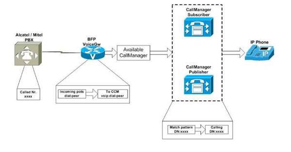
Inbund call routing
All inbound calls come though Cisco 3845 voice gateway, located in BFP site. This gateway forwards calls from PBXs to CallManager, using H.323 interface. The configuration of voice gateway will be discussed later in this document.
The followingg figure describes the inbound call routing.
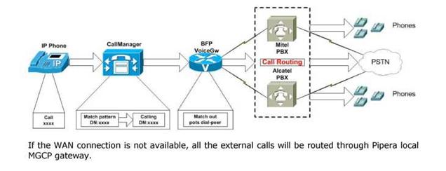
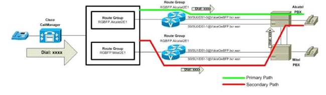
Outbound call routing
The outbound calls are those designated to either PBX users or PSTN users. All outbound calls go throughout Cisco 3845 voice gateway, located in BFP site, using MGCP protocol interface. This gateway forwards calls from CallManager to PBXs, using E1 trunks. Then the trunks perform the final call routing, based on the destination of the phone call. If the destination is a PSTN number, then the PBXs forward the call to Vodafone or Romtelecom. If the destination is an internal phone number, then place the call to proper phone. The configuration of voice gateway will be discussed later in this document.
The following figure describes the outbound call routing.
Class of Restriction
In the network will be defined five main profiles of users based on the type of calls they can do. The profile will be based on:
Internal calls;
Internal and Local calls;
Internal, Local and National calls;
Internal, Local, National and GSM calls;
Internal, Local, National, GSM and international calls.
For Class of Restriction implementation, Partition and Calling Search Spaces are defined.
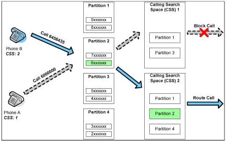
Partitions
A partition is a group of directory numbers (DNs) with similar accessibility, and a calling search space defines which partitions are accessible to a particular device. A device can call only those DNs located in the partitions that are part of its calling search space.
All the IP phones will be inserted in the Interior Numbers Partition, so that they can call each other.
The following partitions are defined:
|
Partition |
Description |
|
DNSibiulnteriors |
Internal numbers |
|
RPSibiuEmergency |
Emergency Services Numbers |
|
RPSibiuLocal |
Contains routes for the local calls for the branch users |
|
RPSibiuNational |
Contains routes for the national calls for the branch users |
|
RPSibiuGSM |
Contains routes for the GSM calls for the branch users |
|
RPSibiulnternational |
Contains route for international calls |
Calling Search Spaces
The Calling Search Spaces needed in the BCR network for each branch are the following:
|
CSS Name |
Partitions |
Description |
|
SibiulnternCSS |
DNSibiulnteriors RPSibiuEmergency |
Internal, |
|
SibiuLocalCSS |
DNSibiulnteriors RPSibiuEmergency RPSibiu Local |
Internal and Local calls, |
|
SibiuNationalCSS |
DNSibiulnteriors RPSibiuEmergency RPSibiu Local RPSibiuNational |
Internal, Local and National calls, |
|
SibiuMobileCSS |
DNSibiulnteriors RPSibiuEmergency RPSibiu Local RPSibiuNational RPSibiuGSM |
Internal, Local, National and GSM calls, |
|
SibiulnternationalCSS |
DNSibiulnteriors RPSibiuEmergency RPSibiu Local RPSibiuNational RPSibiuGSM RPSibiulnternational |
Internal, Local, National, GSM and international calls, |
Route Groups
This section permits to define group of gateways.
In the BCR
solution will be defined only one group for
|
RG Name |
Gateways |
|
RGBFP.Alcatel2El |
SO/SUO/DSl-0@VoiceGwBFP.bcr.wan |
|
SO/SUO/DSl-l@VoiceGwBFP.bcr.wan |
|
|
RGBFP.Mitel2El |
S0/SUl/DSl-0@VoiceGwBFP.bcr.wan |
|
S0/SUl/DSl-l@VoiceGwBFP.bcr.wan |
|
|
RGSibiu.VodafonelEl |
S0/SUl/DSl-0@Bl00_North_Sibiu |
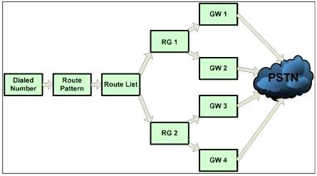
Route List
The route list permits to define a list of route group. The route list will be associated to the route pattern: that means that for a dialed number the Call Manager will have a list of gateways where to send the call in priority order.
For
|
RL Name |
Route Groups |
|
RLBFPAlcatel.BFPMitel |
RGBFP.Alcatel2El |
|
RGBFP.Mitel2El |
|
|
RL. BFPMitel. BFP Alcatel |
RGBFP.Mitel2El |
|
RGBFP.Alcatel2El |
|
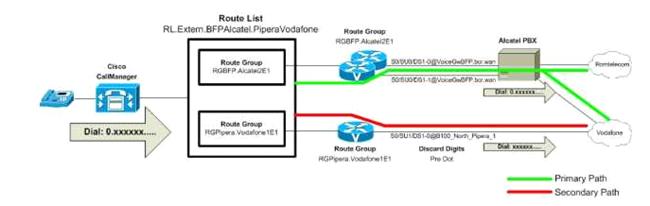
|
RLExtern. BFPAlcatel |
RGBFP.Alcatel2El |
|
RGSibiu.VodafonelEl |
Route Patterns
The route pattern configuration associate finally the dialed number with the partition (so that we can have different groups of phones) and the 'route list' (so that we can have a list of gateways where to send the call to).
For example, for each branch we have:
|
Route Pattern |
Partition |
Route List |
Description |
|
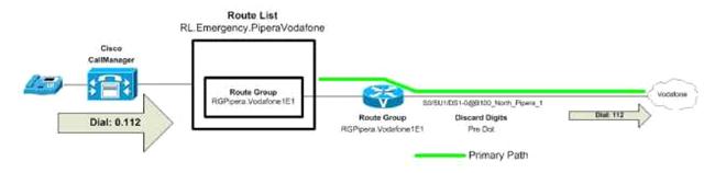
RPSibiuEmergency |
Sibiu_RL |
Sibiu, Emergency |
|
|
xxxx |
RPSibiulntern |
Sibiu_RL |
Sibiu, catre BFP |
|
0.1xxxxxx |
RPSibiu Local |
Sibiu_RL |
Sibiu, Local Calls |
|
0.0[^7]xxxxxxxx |
RPSibiuNational |
Sibiu_RL |
Sibiu, National Calls |
|
0.07xxxxxxxx |
RPSibiuMobile |
Sibiu_RL |
Sibiu, Mobile Calls |
|
0.00xxxxxxxxT |
RPSibiulnternational |
Sibiu_RL |
Sibiu, International Calls |
Outbound call routing procedures
Outbound calls to BFP interiors:
Outbound calls to PSTN interiors:
Emergency calls:
IP Phones
Outbound calls to BFP interiors:
The following types of IP Phones are deployed:
7961 - manager IP phones, grey scale display, full features, incorporated switch;
7911 - regular user phone, grey scale display, incorporated switch.
All ip phones support inline power based on Cisco pre-standard PoE, 802.3af standard inline power or external power.
The phone is controlled by centrally by the CallManager cluster, but transmits voice traffic encoded as RTP packets directly to the destination device across the backbone network. In almost all cases, the phone also provides fastethernet connectivity for the user's workstation, eliminating the need for extra wall outlets and switch pots. To provide for reliability and security, user traffic and voice traffic are separated by the phone and placed irto different VLANs.
For example in the 3560 switches the command:
hostname(config-if)# switch port voice vlan vlan-id

The switch should support the 802.1q standard.
The IP Phones normally retrieve the entire network configuration from a DHCP server. The DHCP server should be configured to assign to the IP phone not only the network parameters (IP address, mask and default gateway) but also the IP address of a TFTP server where the phone can download his configuration (Extension, speed dials services). The TFTP server is one of the Call Manager servers, where are stored all the information about the phones. It is possible to achieve redundancy also with the TFTP server. For each phone it is possible to define up to two TFTP servers where the phone can download his configuration.
Using this method, the IP address of the phone can change (for example moving the phone in another subnet) but his configuration doesn't change.
The information about the TFTP server IP address is passed by the DHCP to the phones using the option 150. This is a user defined option that can be configured as an array of IP addresses. The Call Manager servers will act as TFTP server. The TFTP access is done by the phone only when the phone start-up. The suggestion is to use the CallManager server located in the same site of the phone, as primary server TFTP.
When configuring the phones we need to define some properties on the phone. Typical parameters that we need to configure are:
MAC address - the phone is identified by the Call Manager using the MAC address not using the IP Address
Device Pool - As defined in the previous chapter
Location- for CAC
Lines - for each phone it is possible to define multiple lines and the corresponding extension.
For each line on the phone the typical parameters required are:
Partition and Calling search space - These parameters are used for defining the routing plan as described in the next chapter.
Call Waiting: Enabled/Disabled and how many calls can be putted on waiting.
Call Forward busy, unconditional, no answer.
QoS
To protect voice traffic, some spedai Cisco feature will be activated in Call Manager, voice gateways and LAN switches. These functions will assure that voice bandwidth can be used by data traffic if no voice calls are active. QoS function are mandatory in LAN and WAN for a good voice quality!
The voice traffic and the data traffic will be separated with VLAN configuration, and QoS policy will be applied: on the voice gateway for edge QoS, and on switches for LAN QoS.
The voice traffic (RTP and signalling) will use the Romtelecom WAN connections (100 Mbps speed each).
The voice traffic packet marking is made at the IP Phones, and kept by switches. The ip phones will be defned as trusted points, so the packets won't be remarked when entering the switch.
At this moment, in
mls qos map cos-dscp 0 8 16 26 32 46 48 56
mls qos srr-queue input bandwidth 90 10
mls qos srr-queue input threshold 1 8 16
mls qos srr-queue input threshold 2 34 66
mls qos srr-queue input buffers 67 33
mls qos srr-queue input cos-map queue 1 theshold
mls qos srr-queue input cos-map queue 1 theshold
mls qos srr-queue input cos-map queue 2 theshold
mls qos srr-queue input cos-map queue 2 theshold
mls qos srr-queue input cos-map queue 2 theshold
mls qos srr-queue input dscp-map queue 1 theshold
mls qos srr-queue input dscp-map queue 1 theshold
mls qos srr-queue input dscp-map queue 1 theshold
mls qos srr-queue input dscp-map queue 2 theshold
mls qos srr-queue input dscp-map queue 2 theshold
mls qos srr-queue input dscp-map queue 2 theshold
mls qos srr-queue input dscp-map queue 2 theshold
mls qos srr-queue input dscp-map queue 2 theshold
mls qos srr-queue input dscp-map queue 2 theshold
mls qos srr-queue output cos-map queue 1 threshold 3 5
mls qos srr-queue output cos-map queue 2 threshold 3 3 6 7
mls qos srr-queue output cos-map queue threshold mls qos srr-queue output cos-map queue threshold mls qos srr-queue output cos-map queue threshold
mls qos srr-queue output dscp-map queue threshold
mls qos srr-queue output dscp-map queue threshold
mls qos srr-queue output dscp-map queue threshold
mls qos srr-queue output dscp-map queue threshold
mls qos srr-queue output dscp-map queue threshold
mls qos srr-queue output dscp-map queue threshold
mls qos srr-queue output dscp-map queue threshold
mls qos srr-queue output dscp-map queue threshold
mls qos srr-queue output dscp-map queue threshold
mls qos queue-set output theshold
mls qos queue-set output theshold
mls qos queue-set output theshold
mls qos queue-set output theshold
mls qos queue-set output theshold
mls qos queue-set output theshold
mls qos queue-set output theshold
mls qos queue-set output theshold
mls qos queue-set output buffers
mls qos queue-set output buffers
mls qos
There are two types of port config urations, based on switchport type, both confi g ured by AutoQoS feature:
Access pots:
srr-queue bandwidth share srr-queue bandwidth shape mls qos trust device cisco-phone mls qos trust cos auto qos voip cisco-phone
Tunk ports:
srr-queue bandwidth share srr-queue bandwidth shape queue-set mls qos trust cos auto qos voip trust
Following equipments will be deployed in
Two Routers Cisco 3845:
Two 10/100/1000 FastEthernet ports;
2 1000BASE-LX SFP- FiberOptic ports;
IOS Advance IP Service.
Two Switches Cisco 3750:
12 FiberOptic ports;
Six Switches Cisco 3560:
48 10/100 FastEthernet ports;
2 1000BASE-LX SFP- FiberOptic ports.
IP Phones:
X 7961 grey- scale IP Phones, for managers;
X 7911 grey-scale IP Phone, for normal users;
X ATA 188 , for fax.
|
Politica de confidentialitate | Termeni si conditii de utilizare |

Vizualizari: 3017
Importanta: ![]()
Termeni si conditii de utilizare | Contact
© SCRIGROUP 2026 . All rights reserved