| CATEGORII DOCUMENTE |
| Bulgara | Ceha slovaca | Croata | Engleza | Estona | Finlandeza | Franceza |
| Germana | Italiana | Letona | Lituaniana | Maghiara | Olandeza | Poloneza |
| Sarba | Slovena | Spaniola | Suedeza | Turca | Ucraineana |
COURSE OTC000003
WDM Principle
ISSUE1.1

Contents
1.1 WDM Optical Transmission Technology
1.1.2 WDM Technology Background
1.2 Overview of DWDM Principle
1.3 Transmission Methods of WDM Equipment
1.4 Open and Integrated System
1.7 Brief Introduction to CWDM
Chapter 2 WDM Transmission Media
2.3 Basic Features of Optical Fiber
2.3.1 Physical Dimension (Mode Field Diameter)
Chapter 3 DWDM Key Technologies
3.1.1 Modulation Mode Of A Laser
3.1.2 Wavelength Stability of the Laser
3.2.1 Positive Intrinsic Negative Photodiode (PIN)
3.2.2 Avalanche Photo Diode (APD)
3.3.1 Optical Amplifier Overview
3.3.2 Erbium Doped Fiber (EDF)
3.3.5 Advantages and Disadvantages of EDFA
3.3.7 Related Technical Features
3.4 Optical Multiplexer and Optical Demultiplexer
3.4.1 Optical Grating Type Wavelength Division Multiplexer
3.4.2 Dielectric Film Wavelength Division Multiplexer
3.4.3 Fused Conical Type Wavelength Division Multiplexer
3.4.4 Integrated Optical Waveguide Type Wavelength Division Multiplexer
3.4.5 Performances of Wavelength Division Multiplexing Components
3.4.6 Basic Requirements to Optical Multiplexing Components
3.5 Optical Supervisory Channel
3.5.1 Requirements on Optical Supervisory Channel (OSC)
3.5.2 Interface parameters for supervisory channel
3.5.3 Frame Structure of Supervisory Channel
Chapter 4 Technology Specifications for DWDM Optical Transmission System
4.1 ITU-T Recommendations on WDM
4.2 Definition of Transmission Channel Reference Points
This course mainly introduces the basic knowledge of WDM technologies, expounds key technologies and optical transmission specification of DWDM. Through this course, you will have a relatively complete understanding of the WDM knowledge and the development orientation of optical transmission networks.
This course is divided into four sections as follows:
Section 1 WDM Overview
This section tells you what WDM is, how it derives, the operation modes, structure and characteristics of DWDM. After reading this book, you will have a basic idea of the advancing front technology of optical transmission network WDM.
Section 2 WDM Transmission Media
This section tells us the basic structures and types of optical fibers,and we will learn the characteristics of optical fibers,including attenuator,dispersion and so on.
Section 3 DWDM Key Technologies
From the aspect of hardware, how to implement DWDM when converting it into commercial product? Reading this section with the question, you'll know the key technologies and implementation methods of DWDM, including light sources, components for optical amplification and wavelength division multiplexing, etc.
Section 4 Technical Specifications of DWDM Optical Transmission System
This chapter mainly introduces some proposals and specifications of ITU-T to WDM, and gives us a basic understanding of some of the ITU-T knowledge involved in the WDM system.
To know the basic conception, principle, transmission mode and structure of WDM;
To know the basic structures,types and characteristics of optical fibers;
To know the technical principle of DWDM and the method to implement its key technologies.
To know the technical specifications of DWDM optical transmission system.
(1) Basis for Optical Communication
(2) Guide to DWDM Technologies
(3) DWDM Transmission System Principle and Testing
(4) High Speed Optical Communication ITU-T Specification and System Design
(5) Metropolitan Area Fiber Network
(6) TA052401 Optical Supervisory Channel and Its Application in DWDM ISSUE 1.0
(7) TC000001 Fiber and Optical Components ISSUE1.0
(8) TC000001 Optical Amplifier ISSUE1.0
& Objectives:
To master the basic concepts of WDM
To master the basic principle, communication method and component of WDM
To understand the DWDM background and technical features.
Optical communication system can be classified according to different modes. If it is classified according to signal multiplex mode, it can be classified into FDM (FDM-Frequency Division Multiplexing), TDM TDM-Time Division Multiplexing , WDM WDM- Wavelength Division Multiplexing and SDM SDM-Space Division Multiplexing . FDM, TDM, WDM and SDM refer to optical communication systems classified according to the frequency, time, wavelength and space. It can be said that frequency is closely connected with the wavelength. Frequency division is wave division. But in optical communication system, WDM system adopts optical spectral component that is different from filter adopted in the common communication. So we still classify them into two different systems.
WDM is a kind of transmission technology of fiber communication. Depending on the fact that a fiber can transmit several optical carrier of different wavelengths at the same time, it divides wavelength possibly used by fiber into several bands. As an independent channel, each band transmits a kind of optical signal with a preset wavelength. Optical and wavelength division multiplex is in fact the optical and frequency division multiplex on fiber (OFDM), but optical wave usually use wavelength instead of frequency, to describe, supervise and control. Along with the development of the electric-optical technology, the wavelength density in the same fiber will become very high. Compared with DWDM (DWDM-Dense Wavelength Division Multiplexing), there are still WDM with low densities that are called CWDM (CWDM-Coarse Wave Division Multiplexing).
A fiber can be regarded as a road with several driveways here. The traditional TDM system just uses one of driveways. To increase bit rate is to increase the driving speed in the driveway in order to increase the transportation burden in unit time. To use DWDM technology is similar to using the driveway not yet used, so as to obtain the large transportation capacity to be developed in fiber.
With the rapid development of science and technology, information transmission in communication area expands with accelerated speed. Information Age requires transmission network with larger and larger capacity. In recent years, companies and manufacturers worldwide have paid more and more attention to WDM technology, and been more concerned about it. There are many methods to increase the capacity and flexibility of fiber network, and increase the transmission speed and expand capacity. We shall compare the different expansion methods in the following.
The SDM method increases the transmission capacity linearly by adding the number of optical fibers, and the transmission equipment will be increased linearly, too.
At present, the optical cable manufacturing technology is very much matured, the multi-core band optical cables are widely used, the advanced optical fiber connection technology makes the construction easier, but the increase in the number of optical fibers will inevitably complicate the cable layout and maintenance. If there are not enough optical fibers in the existing optical cable tunnel, you will have to lay down additional cables to expand the capacity, and this method will multiply the engineering cost. This means doesnt make full use of transmission bandwidth of fibers as well and results in the waste of fiber bandwidth resources. As the construction of communication networks, it is impossible to expand capacity by laying down new fibers all the time. In fact, it is very hard to estimate the increasing business demand and the number of fibers that should be laid down at the beginning of the project. Therefore, the method to expand capacity in SDM is very limited.
TDM is also a commonly used method for capacity expansion, e.g. multiplexing of the primary group to the fourth group of the traditional PDH, and STM-1, STM-4, STM-16 and STM-64 of current SDH. TDM technology can enhance the capacity of optical transmission information in duplication and greatly reduce the circuit cost in equipment and line. Moreover, it is easy to extract specific digital signals from the data stream via this multiplexing method. It is especially suitable for networks requiring the protection strategy of self-healing rings.
However, TDM method has two disadvantages. Firstly, Upgrading affects services. An overall upgrade to higher rate levels required to replace the network interfaces and equipment completely. Thus the equipment in operation must be interrupted during the upgrade process. Secondly, rate upgrade lacks flexibility. Let's take SDH as an example, when a system with a line rate of 155Mbit/s is required to provide two 155Mbit/s channels, the only way is to upgrade the system to 622Mbit/s even though two 155Mbit/s are idle.
Presently, TDM equipment of higher rate costs much more, and the 40Gbit/s TDM equipment has reached the rate limit of the electronic component. Even for the rate of 10Gbit/s, its non-linear effect in different types of optical fibers will exert various limitations on the transmission.
Currently, the TDM technology is widely used for the capacity expansion since it can expand the capacity by constantly upgrading the system rate. But when the rate reaches a certain level, the limitation due to the component and line features will drive you to look for other solutions.
All the basic transmission networks, whether using SDM or TDM to expand the capacity, adopt traditional PDH or SDH technology, i.e. utilizing optical signals on a single wavelength for transmission. This transmission method is a great waste of optical capacity because the bandwidth of optical fiber is almost infinite when compared to the single wavelength channel we currently use. We are worrying about the jam of networks, on the other hand huge network resources are being wasted.
WDM utilizes the large bandwidth of low loss band section in single-mode fibers to transmit by mixing optical signals with various rates (wavelengths). The digital signals carried by optical signals with different wavelengths can be either the format of the same rate and protocol or the format of different rates and protocal. We can determine the network capacity according to requirement of the users by adding new features of wavelength. For the WDM with rate under 2.5Gb/s, the current technology can completely overcome the limitation due to the fiber dispersion and fiber non-linear effect. It can satisfy various requirements for transmission capacity and transmission distance. The disadvantage of WDM is that it needs many fiber components and increases the failure probability.
It is the application direction to make use of the technology advantages of TDM and WDM for network capacity expansion. We can choose the highest transmission rate of TDM according to fibers of different types. On this basis, we can choose the number of WDM optical channels according to the transmission capacity and use the maximum optical carriers under the possible condition. Undoubtedly the transmission capacity of multi-channel is forever bigger than that of single channel and is more economical.
Based on such features as bandwidth and low loss of the single mode optical fiber, the DWDM technology uses multiple wavelengths as carriers and allows the signals to be transmitted simultaneously over the carrier channels in the optical fiber. Compared with the general single channel system, the dense WDM (DWDM) not only drastically increases the communication capacity of the network system and fully uses the bandwidth of the optical fiber, but also has many advantages, such as simple expansion and reliable performance, especially it can directly access multiple services, so it enjoys bright prospects.
In analog carrier communication systems, the frequency division multiplexing (FDM) method is often adopted to make full use of the bandwidth resources of cables and enhance the transmission capacity of the system. That is, to transmit several signals of different frequencies simultaneously in the same cable and, at the receiver end, to utilize band-pass filters to filter the signal on each channel according to the frequency differences among the carriers.
In the same way, in optical fiber communication systems, optical frequency division multiplexing method can also be used to enhance the transmission capacity of the systems. In fact, this multiplexing method is very effective in optical communication systems. Unlike the frequency division multiplexing in analog carrier communication systems, optical fiber communication systems utilize optical wavelengths as signal carriers, divide the low attenuation window of optical fibers into several channels according to the frequency (or wavelength) difference of each wavelength channel and implement multiplexing transmission of multi-channel optical signals in a single fiber.
Since some optical components (such as narrow-bandwidth optical filters and coherence light source) are currently very immature, it is difficult to implement the ultra-dense optical frequency division multiplexing (coherence optical communication technology) of optical channels. However, alternate-optical-channel frequency division multiplexing can be implemented based on the current component technical level. Usually, multiplexing with a larger channel spacing (even in different windows of optical fibers) is called optical wavelength division multiplexing (WDM), and DWDM in the same window with smaller channel spacing is called dense wavelength division multiplexing (DWDM). With the progresses of sciences & technologies, the multiplexing of the nanometer level wavelength spacing can be implemented by using modern technologies. Even the multiplexing of sub-nanometer level wavelength spacing can be implemented, only need stricter component technical requirements . Hence, multiplexing of 8, 16, 32 or more wavelengths with smaller wavelength spaces is called DWDM.ITU-T G.692 suggests, the absolute reference frequency of DWDM is 193.1THz (the corresponding wavelength is 1552.52nm), different wavelength frequency spacing should be integral multiple of 100GHz (corresponding wavelength spacing is about integral multiple of 0.8nm).
Diagram of DWDM system structure and spectrum is shown in figure
Figure 1-1 Composition and spectrum illustration of the DWDM system
At the transmitting end, the optical transmitter sends out the optical signals whose wavelengths are different but whose accuracy and stability satisfy certain requirements, such signals are multiplexed together through the optical wavelength multiplexer and sent to the EDFA (Erbium Doped Fiber Amplifier) (the EDFA is used mainly to compensate for the optical power loss caused by the multiplexer and improve the transmitting power of the optical signal), then the amplified multi-channel optical signals will be sent to the optical fiber for transmission, when they get to the receiving end through or not through the optical line amplifier, where they will be amplified by the preamplifier (used to improve the receiving sensitivity to extend the transmission distance), then they will be sent to the optical wavelength demultiplexer to split the channels of optical signals.
As shown in Figure 1-2, the unidirectional WDM system adopts two optical fibers. One only implements the transmission of signals in one direction while the other implements the transmission of the signals in the opposite direction.
Figure 1-2 Unidirectional transmission mode of WDM
This kind of WDM system can fully exploit the huge bandwidth resources of the optical fiber and expand the transmission capacity of a single optical fiber to several or tens of times. In long-haul networks, capacity can be expanded by adding wavelengths gradually according to the demands of practical traffic, which is very flexible. Under the prerequisite that the actual fiber dispersion is unknown, it is also a means to use multiple 2.5Gbit/s systems to implement the ultra-large capacity transmission to avoid adopting ultrahigh speed optical systems.
As shown in Figure 1-3, bi-directional wave WDM system utilizes only one optical fiber. The single fiber transmits optical signals in both directions simultaneously, and the signals in the different directions should be assigned on different wavelengths.
The single fiber bi-directional transmission mode allows a single fiber to carry full duplex channels and, usually, saves a half of the fiber components of unidirectional transmission. Since signals transmitted in both directions do not interact and create FWM (Four-Wave Mixing) products, its total FWM effect are much less than that of the two-fiber unidirectional transmission. However, the disadvantage of this system is that it requires a special measure to deal with the light reflection (including discrete reflection resulted by optical connectors and Rayleigh backward reflection of the fiber) to avoid multi-path interference. When the optical signal needs to be amplified to extend the transmission distance, components such as bi-directional optical fiber amplifier and optical circulator must be adopted, but their noise coefficients are a bit poor.
Figure 1-3 WDM bi-directional transmission mode
In the ITU-T recommendations G.692 document, no clear opinion is given on adopting the single fiber bi-directional WDM transmission mode or double fiber unidirectional WDM transmission mode. Most feasible WDM systems adopt the double fiber unidirectional transmission mode.
The DWDM is usually applied in two modes:
l Open DWDM
l Integrated DWDM
The feature of open DWDM system is that it has no special requirements for multiplex terminal optical interfaces, the only requirement is that these interfaces meet the optical interface standards defined in ITU-T.DWDM system adopts wavelength conversion technology to convert the optical signal of the multiplex terminal into the specific wavelength. Optical signals from different terminal equipment are converted into different wavelengths meeting the ITU-T recommendation, which are then multiplexed.
The integrated DWDM system does not adopt the wavelength conversion technology, instead, it requires that the wavelength of the optical signals at the multiplex terminal conforms to the specifications for the DWDM system, and that different multiplex terminal equipment sends different ITU-T wavelengths complying with ITU-T recommendation, so that the wavelengths can occupy different paths to enter the coupler, thus they can be combined together.
Different application modes can be adopted according to the demands of engineering. In practical applications, open DWDM and integrate DWDM can be mixed.
The overall structure of the WDM system of N-channel wavelength is composed of transmission optical multiplexing terminal unit, receiving optical multiplexing terminal (OMT) unit and optical relay line advanced (OLA) unit. If it is classified by composition modes, there are:
l Optical tansponder unit(OTU)
l Wavelength division multiplexer: optical demultiplexer unit/optical multiplexer (ODU/OMU)
l Optical amplifier( BA/LA/PA)
l Optical Supervisory Channel( OSC)
Optical wavelength transfer unit converts wavelength into standard wavelength specified in ITU-T. System utilizes the conversion of optical/electricity/optical (O/E/O), i.e. uses photodiode to convert optical signal received into the electrical signal, and then electrical signal will converted into optical signal with specfic wavelength, so as to get the new optical wavelength signal that meets the requirements.
Wavelength division multiplexer can be classified into transmitting optical multiplexer. Optical multiplexer is used in the transmitting end of the transmission system. It is a component with several input ports and one output port. Each of its input port inputs optical signal of a preset wavelength. Input lightwaves of different wavelengths export from the same output port. Optical demultiplexer is used in the receiving end of transmission system. Opposite to optical multiplexer, it has an input port and several output ports which classify different wavelength signals.
Optical amplifier not only can directly amplify the optical signal but also features the all optical amplifier of real time, high gain, broadband, online, low noise. It is the indispensable key component in the new fiber communication system. The fiber amplifier currently used mainly has the EDFA (Erbium-Doped Fiber Amplifier), SOA (Semiconductor Optical Amplifier), and FRA (Fiber Raman Amplifier) etc. Among them, EDFA is widely used in fiber communication system of long distance, big capacity and high rate and is used as preamplifier, line amplifier and power amplifier.
Optical supervisory channel is set for the supervision of WDM optical transmission system.The 1510nm wavelength, capacity of 2Mbit/s should be preferentially adopted. Receiving sensitivity ( better than 50dBm) of low rate can still work normally. But it must go down optical path before EDFA and go up optical path after EDFA.
The capacity of optical fiber is huge. However, traditional optical fiber communication systems, with one optical signal transmitted in a single fiber, only exploited a little part of the abundant bandwidth of optical fiber. To fully use the huge bandwidth resources of optical fiber and increase its transmission capacity, a new generation optical fiber communication technology based on the dense WDM (DWDM) has emerged.
The DWDM technology has the following features:
The transmittable bandwidth of the current widely used conventional fiber is very wide, but the utilization ratio is still low. By using DWDM technology, the transmission capacity of a single optical fiber is increased by several, tens of or even hundreds of times when compared to the transmission capacity of single wavelength systems. The current highest commercial transmission capacity is 1.6 T bit/s.
DWDM systems conduct multiplexing and de-multiplexing in terms of optical wavelength differences and are independent of signal rates and modulation modes, which is transparent to the data. A WDM system service can carry service signal of many formats, such as ATM, IP or signals that may appear in the future. WDM implements the transparent transmission. For signal at the service layer, each optical wavelength channel in the WDM system is like the virtual optical fiber.
In expanding and developing the network, it is not necessary to make changes to the optical cable lines, instead, you can just change the optical transmitter and receiver, so this is an ideal expansion method and also a convenient way to introduce the broadband services (such as CATV, HDTV and B-ISDN etc). With an additional wavelength, you can add any new service or new capacity you want.
When compared to the traditional networks using electrical TDM networks, new communication networks based on the WDM technology are greatly simplified in architecture and have clear network layers. Dispatching of various services can be implemented simply by adjusting the corresponding wavelengths of the optical signals. Because of the simple network architecture, clear layers and convenient service grooming, the flexibility, economy and reliability of networking are obvious.
It is foreseeable that, in the all optical networks realizable in the future, processing of telecommunication services adding/dropping and cross connections is implemented by changing and adjusting the optical signal wavelengths. So WDM technology is one of the key technologies to implement all optical networks. Moreover, WDM systems can be compatible with future all optical networks. It is possible to implement transparent and highly survivable all optical networks based on the existing WDM system.
DWDM (Dense Wavelength Division Multiplexing) is undoubtedly the preferable technology in the current fiber application area, but on the other hand it is very expensive. Is it possible to enjoy the WDM technology at a low cost? To meet this demand, CWDM (coarse wavelength division multiplexing) emerges.
Telling from the name, CWDM is the close relative of DWDM. They are different in two aspects: (1) Carrier channel spacing of CWDM is wide, so a single optical fiber can multiplex 2 to 16 optical wavelengths. That is why they are called coarse or dense; (2) CWDM modulate laser adopts the uncooled laser, while DWDM adopts the cool laser and needs the cooldown technology to stabilize the wavelength, which is very hard to implement and costs too much. CWDM avoids this difficulty. The DFB laser adopted by CWDM system does not need cooling, so it greatly reduces the cost. The cost of whole CWDM system is only 30% of the cost of DWDM. As more and more metropolitan area network operators begin to seek for more reasonable transmission methods, CWDM is more and more widely used in the industry.
The spacing between different wavelengths in the same optical fiber is the main parameter to separate DWDM from CWDM. The CWDM currently used generally works from 1270nm band to 1610nm, the spacing is 20nm, and can multiplex 16 wavelength channels.
Compared with the DWDM system, the CWDM greatly reduces the system cost while providing certain amount of wavelength and transmission distance within 100 kilometers. It is also very flexible. Hence the CWCM system is mainly applied to metropolitan area network. With very low cost, CWDM provides very high access bandwidth that is suitable for all kinds of popular network architecture such as point to point, Ethernet, SONET ring etc. It is especially suitable for the communication occasion of short distance, high bandwidth and dense access point such as network communication inside a building or between buildings.
However CWDM is the compromise of cost and performance and inevitably has some limitations on performance. The experts within the industry point out the following Three disadvantages that currently exist in CWDM: (1) there are a few multiplexing wavelengths supported by CWDM in the single fiber, which cause the high cost in the future capacity expansion; (2) the cost of equipment such as multiplexer and multiplexing modulator etc should be further reduced. These equipment should be more than simple modification of the corresponding DWDM equipment; (3) No standard has yet been formulated for CWDM.
To summarize, in the middle of 1990s, driven by the market
demand and technology development, WDM developed quickly both in
What are WDM, DWDM and CWDM?
Briefly introduce two transmission modes of WDM equipment.
What is the open and integrated system?
Briefly introduce the composition of the WDM system.
& Objectives:
To master basic structures and types of optical fibers.
To know basic characteristics of optical fibers.
The kernel of optical fiber used in communication systems consists of a cylindrical glass core and a glass cladding. The outermost layer is a plastic wear-resisting coating. The whole fiber is cylindrical. The typical structure of optical fiber is shown in Figure 2-1.

Figure 2-1 The typical structure of optical fiber
Figure 2-2 Three typical types of optical fibers
Thickness of the core and refractive indexes of the core material and cladding material are critical to the properties of the fiber. Figure 2-2 shows three typical optical fibers. As can be seen from this figure, there are two typical refractive index distributions in the fiber core-cladding cross-section. One is that the refractive index radial distributions of the core and the cladding are uniform, and the change of refractive index at the core-cladding boundary is a step function. This fiber is called step-index fiber. The other one is that the refractive index of the core is not a constant. It gradually decreases as the radial coordinate of the core increases until it equals to the index of the cladding. Hence this fiber is called graded-index fiber. The common feature of this two fiber cross-section is that the refractive index of the core n1 is larger than that of the cladding n2. This is also a necessary condition for the optical signal to transmit in the fiber. For a step-index fiber, total internal reflection can occur at the core-cladding boundary and the light wave can propagate along the core. For a graded-index fiber, the continuous refraction occurs to the light wave in the core, forming a light ray similar to the sine-wave through the fiber axis and guiding the light wave to propagate along the core. The tracks of the two light rays are shown in Figure 2-2. With the difference of the diameter size of the core of step-index and graded-index fibers, the number of modes transmitted in the fiber is different. Hence, step-index fiber or graded-index fiber can be classified into single mode fiber and multimode fiber according to the number of transmission modes. This is also a classification method of optical fiber. The core diameter of a single mode fiber is very small and, generally, less than 10mm, and the core diameter of a multimode fiber is relatively large and often equal to 50mm. However, there is little difference between the profiles of these two types of fiber. The diameters of fibers with a plastic jacket are less than 1mm.
Since the single-mode optical fiber has advantages of low internal attenuation, large bandwidth, easy upgrade and capacity expansion and low cost, it is internationally agreed that DWDM systems will only utilize single mode fiber as transmission media. At present, ITU-T has defined four types of single mode optical fiber with different design in Recommendations G.652, G.653, G.654 and G.655.
G.652 fiber is currently a single mode fiber for extensive use, called 1310nm property optimal single mode fiber and also called dispersion unshifted fiber. According to the refractive index cross section of the core, it can also be divided into two categories: matched cladding fiber and depressed cladding fiber. They have similar properties. The former is simple in manufacturing but has relatively larger macrobend loss and microbend loss while the later has larger connection loss.
G.653 fiber is called dispersion shifted fiber or 1550nm property optimal fiber. By designing the refractive index cross section, the zero dispersion point of this kind of fiber is shifted to the 1550nm window to match the minimum attenuation window. This makes it possible to implement ultrahigh speed and ultra long distance optical transmission.
G.654 fiber is cut-off wavelength shifted single mode fiber. This kind of fiber is mainly designed to reduce the attenuation at 1550nm. Its zero dispersion point is still near 1310nm. The dispersion at 1550nm is relatively high, up to 18ps/(nm.km). So single longitudinal mode laser must be used to eliminate the affect of the dispersion. G.654 fiber is mainly used for submarine optical fiber communication with very long regenerator section distance.
G.655 fiber, a nonzero dispersion shifted single mode optical fiber, is similar to G.653 fiber and preserves certain dispersion near 1550nm to avoid four-wave mixing phenomenon in DWDM transmission. It is suitable for DWDM system applications.
Except for the above-mentioned four types of standardized fiber, a large effective area fiber suitable for higher capacity and longer distance has emerged. Its zero dispersion point is near 1510mm and its effective area is up to 72 square mm Therefore, it can effectively overcome the nonlinear affects and is especially suitable for DWDM system applications based on 10Gbit/s.
Thought:
Which type of optical fiber is widely laid at present?
The fiber core diameter of a single mode fiber is 8~9mm in the same magnitude as the operating wavelength 1.3~1.6mm. Because of the optical diffraction effect, it is not easy to measure the exact value of the fiber cord diameter. In addition, since the field intensity distribution of the fundamental mode LP01 isn't confined within the fiber core, the concept of single mode fiber core diameter is physically meaningless and should be replaced with the concept of mode field diameter. Mode field diameter measures the concentrate level of the fundamental mode field spatial intensity distribution within the fiber.
The nominal mode filed diameter of G.652 fiber at 1310nm wavelength area should be 8.6~9.5mm with a deviation of less than 10%, and the nominal mode filed diameter of G.655 fiber at 1550nm wavelength area should be 8~11mm with a deviation of less than 10%.
The cladding diameter of both types of above-mentioned single mode optical fibers is 125mm
Attenuation in optical fiber is mainly determined by three
types of loss: absorption loss, scattering loss and bend loss.
Absorption loss is caused by the fiber material where
excessive metal impurity and
Scattering loss is often caused in the case that a part of optical power is scattered outside the fiber when uneven refractive index distribution local area emerges within the fiber and causes light scattering because of the micro-change in fiber material density and uneven density of compositions such as SiO2, GeO2 and P2O5. Or, scattering loss can be aroused if some defect occurs or some bubbles and gas scabs are remained at the core-cladding boundary. The physical dimension of these structural defects is much larger than the lightwave, causing wavelength independent scattering loss and upward shifting the whole curve of fiber loss spectrum. However, this kind of scattering loss is much less than the former one.
Combining the above losses, the attenuation constant of single mode fiber at 1310nm and 1550nm wavelength areas is 0.3~0.4dB/km (1310nm) and 0.17~0.25dB/km (1550nm), respectively. As defined in ITU-T Recommendation G.652, the attenuation constant at 1310nm and 1550nm should be less than 0.5dB/km and 0.4dB/km, respectively.
Dispersion in optical fiber refers to a physical phenomenon of signal distortion caused when various modes carrying signal energy or different frequencies of the signal have different group velocity and disperse from each other during propagation. Generally, three kinds of dispersion exist in optical fiber.
1) Modal dispersion: This is caused when the fiber carries multiple modes of the same frequency signal energy and different mode has different time delay during transmission.
2) Material dispersion: Because the refractive index of the fiber core material is a function of the frequency, signal components of different frequency propagate at different velocities along the fiber. This causes dispersion.
3) Waveguide dispersion: In the fiber, for a signal carrying different frequencies in the same mode, dispersion is caused because of different group velocities during propagation.
These three types of dispersion are called chromatic dispersion. ITU-T G.652 defines a zero dispersion wavelength range of 1300nm~1324nm and a maximum dispersion slope of 0.093ps/ nm2.km). In the wavelength range of 1525~1575nm, the dispersion coefficient is approximately 20ps/(nm.km). ITU-T G.653 defines a zero dispersion wavelength 1550nm and a dispersion slope of 0.085ps/ nm2.km) in the wavelength range of 1525~1575nm where the maximum dispersion coefficient is 3.5ps/(nm.km). The absolute value of the dispersion coefficient of G.655 fiber should be within 0.1~6.0 ps/(nm2.km) in the range of 1530~1565nm.
& Technical details:
The following figure shows the dispersion characteristics of several types of fiber.

What are the basic structures and types of optical fibers?
What kinds of dispersion are there in the optical fiber?
& Objective:
To understand the requirements and solutions of DWDM light sources
To understand the DWDM optical amplification technology.
To understand the DWDM Multiplex/Demultiplex technology
To understand the DWDM Optical Supervisory Channel
The function of light sources is to generate laser or fluorescent light, and light sources are important devices to constitute the optical fiber communication system. The semiconductor laser LD (Laser Diode) and semiconductor LED (Light Emitting Diode) used as light sources for optical fiber communication are both semiconductor devices. Their common features are small in dimension, light in weight and low in power consumption.
The major difference between LD and LED is that LD generates laser and LED generates fluorescent light. So, LED has a wider spectrum bandwidth with low modulation efficiency and low coupling efficiency with optical fiber; but its output characteristics curve is of better linearity, and it has a long service life and low cost, thus it is suitable for short-distance and small-capacity communication systems. And LD is typically applicable to long-distance and large-capacity communication systems, and is widely used in high-speed PDH and SDH equipment.
The light sources used in high-speed optical fiber communication systems are classified into two categories: MLM lasers and SLM lasers. The major difference between the two types of semiconductor lasers in terms of their performance lies in their emitting spectrum. The emitting spectrum bandwidth of MLM laser is comparatively wider and of the nm order, and multiple harmonic peaks can be observed. The emitting spectrum bandwidth of SLM laser is of 0.1 nm order, and only single harmonic peak can be observed. The monochromatism of SLM laser is better than that of MLM laser.
The operating wavelengths of DWDM systems are relatively dense. Generally, the wavelength spacing is from several nanometers to sub-nanometers. Hence, the laser diode is required to operate at a standard wavelength and possess good stability. On the other hand, the non-electrical regeneration relay distance of DWDM systems is increased from 50~60km transmitted by a single SDH system to 500~600km. The light sources of the DWDM system are required to use lasers more advanced in technology and more excellent in performance in order to elongate the dispersion limited distance of the transmission system and to overcome the nonlinear effects of the fiber .
To sum up, the light source of the DWDM system has two outstanding features:
Larger dispersion tolerance value;
Standard and stable wavelength.
At present, the optical fiber communication systems in wide use employ intensity modulation direct detection system. There are two types of intensity modulation for light sources, i.e. direct modulation and indirect modulation.
Direct modulation is also called internal modulation, i.e. to modulate the light source directly and change the output light wave intensity by controlling the injection current into the semiconductor laser. LED or LD sources used in traditional PDH and SDH systems under the rate of 2.5Gbit/s employ this modulation mode.
One characteristic of direct modulation is that the output power is in proportion to the modulation current. It has the advantages of simple structure, low loss and low cost. However, changes of the modulation current will result in the changes of the length of the laser resonant cavity, which will cause a linear variation of the emitting laser wavelength corresponding to the current. This variation, called modulation chirp, is actually a kind of wavelength (frequency) jitter inevitable for direct modulation of the sources. The chirp broadens the bandwidth of the emitting spectrum of the laser, deteriorates its spectrum characteristics and limits the transmission rate and distance of the system. Generally, for conventional G.652 optical fiber, the transmission distance is 100km and the transmission rate 2.5Gbit/s.
For DWDM systems without optical line amplifiers, direct modulation of the lasers can be considered to save the cost.
Indirect modulation:This modulation method is also called external modulation, i.e. not to modulate the laser directly but to add an external modulator in the laser output path to modulate the light wave. In fact, this modulator works as a switch. Its structure is shown in Figure 3-1.
The constant light source is a highly stable source which continuously emits a fixed wavelength and power. It is not affected by the electric modulation signal during light emision, so no modulating frequency chirp occurs and the bandwidth of its optical spectrum keeps at minimum. According to the electric modulation signal, the optical modulator processes the highly stable laser light from the constant light source in an enabled or disabled manner. During the modulation process, the spectrum characteristics of the light wave will not be affected, ensuring .the quality of the spectrum.
Lasers adopting indirect modulation are relatively complex with big loss and high cost, but its modulating frequency chirp is very low. It can be used in systems with the transmission rate 2.5Gbit/s and transmission distance longer than 300km. Hence, in DWDM systems with optical line amplifiers, the lasers for transmission are generally indirectly modulated.

Figure 3-1 Structure of the external modulated laser
External modulators frequently used are electro-optic modulators, acoustic-optical modulators and waveguide modulators.
The basic operating principle of the photoelectric modulator is the crystal linear electric-optical effect. The electric-optical effect refers to the phenomenon that the electric field causes the variation of the refractive index of a crystal. A crystal that is able to generate the electric-optical effect is called electric-optical crystal.
The acoustic-optical modulator is made by utilizing the acoustic-optical effect of the medium. Acoustic-optical effect refers to the phenomenon that the medium changes under the pressure of an acoustic wave when it propagates through the medium. This change causes the variation of the refractive index of the medium, thus affecting the transmission characteristics of the light wave.
The waveguide modulator is manufactured by diffusing titanium (Ti) into LiNbO2 substrate material, then making the specific waveguide dimensions by the photolithography process. It has many advantages such as small in size, light in weight and easy for optical integration.
According to the integration or separation conditions of the light source and the external modulator, external modulated lasers can be classified into two categories: integrated external modulated laser and separated external modulated laser.
As a maturing technology, integrated external modulation becomes the development trend of DWDM light sources. The commonly used modulators are electro-absorption modulators which, small and compact and integrated with the light source, meet most application requirements in their performances.
Electro-absorption modulator, a kind of loss modulator, operates at the boundary wavelength of the material absorption region. When the modulator isn't biased, the wavelength from the laser is out of the absorption range of the modulator material. Thus the launched power of this wavelength is maximum and the modulator is turned on. When the modulator is biased, the boundary wavelength of the material absorption region shifts and the wavelength from the laser is within this region. Thus the launched power is minimum and the modulator is turned off, as illustrated in Figure 3-2.
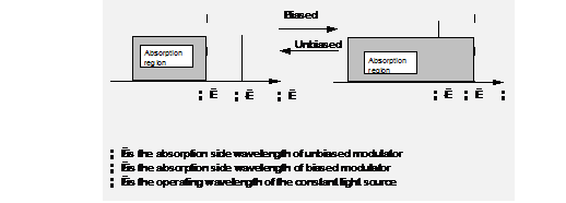
Figure 3-2 Variation of the absorption wavelength of the electro-absorption modulator
The electro-absorption modulator can be manufactured with the same technological process as for the semiconductor laser. Therefore, it is easy to integrate the laser and the modulator, suitable for batch production. So its development is fast. For example, An InGaAsP photoelectric integrated circuit is to integrate a laser and an electro-absorption modulator on a single chip, which is then put on a thermoelectric cooler (TEC). This typical photoelectric integrated circuit is called electro-absorption modulated laser (EML). It can support the signal transmission of 2.5Gbit/s over 600km, far beyond the transmission distance of directly modulated lasers. Its reliability is similar to that of standard OFB lasers with an average service life of 20 years.
The separated external modulated laser generally uses the constant output laser (CW + LiNbO3} Mach-Zehnder external modulator, as illustrated in Figure 3-3.
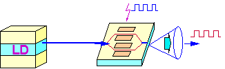
Figure 3-3 M-Z external modulator
This modulator separates the light input into two equal signals which enter the two optical branches of the modulator respectively. These two optical branches employ an electro-optical material whose refractive index changes with the magnitude of the external electrical signal applied to it. Changes of the refractive index of the optical branches will result in the change variation of the signal phases. Hence, when the signals from the two branches recombine at the output end, the combined optical signal is an interference signal with varying intensity. With this method, the information of the electrical signal is transferred onto the optical signal and optical intensity modulation is implemented. The frequency chirp of the separated external modulated laser can be equal to zero. Moreover, its cost is relatively low compared to the electro-absorption modulated external laser.
In the DWDM system, wavelength stability of the laser is a critical problem. According to the requirement of recommendation, the deviation of the central wavelength should not be greater than one fifth of the optical channel interval.
Because the optical channel interval is very small (possibly as low as 0.8nm), the DWDM system has strict requirements to the wavelength stability of the lasers. For example, a 0.5nm variation of the wavelength can shift an optical channel to another one. In practical systems, the variation should be controlled within 0.2nm. The specific requirement is determined according to the wavelength spacing, i.e. the smaller the interval, the higher the requirement. So the lasers should adopt strict wavelength stabilization technology.
Fine tuning of the wavelength of the integrated electro-absorption modulated laser is mainly implemented by adjusting the temperature. The temperature sensitivity of the wavelength is 0.008nm/C. The normal operating temperature is 25C. By adjusting the chip temperature in the range of 15C to 35C, the EML can be adjusted to a specific wavelength with an adjustable range of 1.6nm. The chip temperature is adjusted by changing the drive current of the cooler and then stabilized at a basically constant value by using a thermal resistance as feedback.
According to the corresponding characteristics of the wavelength and chip temperature, the distributed feedback laser (DFB) controls its wavelength by controlling the temperature of the laser chip to achieve wavelength stability. For the 1.5ųm DFB laser, the wavelength-temperature coefficient is about 0.02nm/C and its central wavelength meets the requirement within the range of 15C-35C. This temperature feedback control method completely depends on the chip temperature of the DFB laser. At present, MWQ-DFB laser technology can guarantee that the wavelength deviation meets the requirements of the DWDM system during the service life (20 years) of the laser.
In addition to the temperature, the drive current of the laser can also affect the wavelength. The sensitivity is 0.008nm/mA, smaller than the effect of the temperature in one order. In some cases, this effect can be ignored. Additionally, encapsulation temperature may also affect the device wavelength (e.g. temperature conduction by connection wires from the encapsulation to the laser platform and inward radiation from the encapsulation package will also affect the device wavelength). In well-designed encapsulation, its effect can be controlled to minimum.
The above methods can effectively solve the problem of short-term wavelength stability. However, they are incapable of dealing with long-term wavelength variations caused by factors such as laser aging. It is ideal to directly utilize a wavelength sensitive component for wavelength feedback control of the light source. The principle diagram is shown in Figure 3-4. Standard wavelength control and reference frequency disturbance wavelength control in this type of control solutions are under development and quite promising.
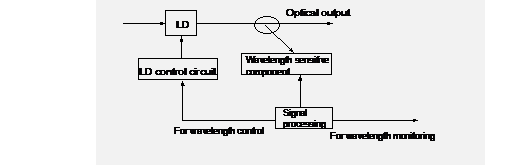
Figure 3-4 Wavelength control principle
? Think It Over:
Why does the DWDM system set strict requirements to the wavelength stability?
The function of photoelectric detector is to convert the received optical signal to corresponding electric signal. Generally, the optical signal sent from the optical fiber is rather weak, so very high requirements are put forward to the photoelectric detector.
Its responsivity in operating wavelength range should be high enough.
The additional noise caused by the photoelectric conversion process should be as low as possible.
It should work at a high response speed, with good linear properties and wide frequency range, the signal distortion should be as less as possible.
It should work stably and reliably, and has comparatively satisfactory stability and long service life.
Small in size and convenient in use
There are two types of semiconductor photoelectric detectors that can satisfy the above requirements: positive intrinsic negative (PIN) photodiode and avalanche photodiode.
PIN photodiode is a semiconductor device, it is composed of an intrinsic (light doped) area between the P type and the n type, When this device is inversely biased, an almost infinite internal resistance appears (just like open circuit), and the output current is in proportion to the input optical power.
PIN photodiode has the advantages of low cost and easy use, but its response speed is slow.
In long-distance optical fiber communication systems, optical power of only several milliwatts is emitted from lasers and through long-distance fiber transmission to reach the receiving end. The optical signal received at the receiving end is very weak, generally only about several nanowatts. If a PIN photodiode is used for detection, the output current will be of only several nanowatts. The output current must go through multistage amplification in order to make the judgment circuit of the photoreceiver work normally. In the signal amplification process, various types of circuit noise will be inevitably introduced thus decreasing the signal-to-noise ratio of the photoreceiver and degrades its sensitivity. Another kind of photodiode with the internal current amplification function is adopted in optical fiber communication systems in order to overcome the above shortcomings of PIN photodiode, that is APD. APD multiplies the optical current utilizing the avalanche multiplication effect of photo-generated carriers in the depletion region. The avalanche multiplication effect means that a strong electric field will be formed in the depletion region when a high reverse bias voltage is applied to the P-N junction. When photons are absorbed in the depletion region, photo-generated carriers are excited and accelerated by the strong electric field, and collide with the crystal lattice in the depletion region at a very high speed. Thus new photo-generated carriers are generated, forming a chain reaction. Therefore, the optical current is multiplied in the photodiode.
The gain and response speed of the avalanche photodiode is better than those of the PIN photodiode, but the noise characteristic of the avalanche photodiode is not so satisfactory.
We know that there is attenuation of the optical fiber, optical signals will attenuate during transmission along the optical fiber, and the transmission distance is thus limited by attenuation. So, we have to amplify optical signals in order to transmit them through a longer distance. A traditional way to amplify optical signals is to use regenerators. But there are several disadvantages with this method. First, a regenerator can only work under a determined signal-bit rate in a determined signal format, different bit rates and signal formats require different regenerators. Second, every channel needs a regenerator, which results in high network cost. So, people wish to find a way to amplify optical signals without regenerators, that is the optical amplification technology.
Optical amplifiers amplify optical signals in a simply way, as illustrated in Figure 3-5:
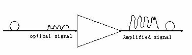
Figure 3-5 OA
Optical amplifiers do not need to convert optical signals into electric signals and then convert them back into optical signals. Compared to regenerators, optical amplifiers have two major advantages thanks to the above feature. First, optical amplifiers simply amplify any signal they receive, so they support any bit rate and signal format. This property is often described as that optical amplifiers are transparent to any bit rate and signal format. Second, optical amplifiers support not only the amplification of single signal wavelength like a regenerator, but also the amplification of optical signals in a certain wavelength rage. And only optical amplifiers support the time-division multiplexing and wavelength division multiplexing networks with various bit rates, various modulation formats and different wavelengths. In fact, WDM technology did not play an important role in optical fiber communication until optical amplifiers, especially EDFA, appeared. EDFA is the most popular optical amplifier, its appearance has turned the wavelength-division multiplexing and all-optical network theory into reality.
At present, there are two major types of optical amplifier in use: semiconductor optical amplifier (SOA) and fiber optical amplifier (FOA). SOA is actually the active medium of the semiconductor laser. In another word, a semiconductor amplifier is a laser diode without or with little optical feedback.
FOA is different from SOA, the active medium (or gain medium) of FOA is a segment of special optical fiber or transmission optical fiber which is connected to the pumping laser. An optical signal will be amplified when it goes through this fiber segment. FOA can be classified into Rare Earth Ion Doped Fiber Amplifier and Non-linear Fiber Amplifier. Just like SOA, the operation theory of the rare earth ion doped fiber amplifier is also the stimulated radiation. And the non-linear fiber amplifier utilizes the non-linear effect of the fiber to amplify the optical signal. EDFA and Raman fiber amplifier are fiber amplifiers in practical application.
As a key component of new generation optical communication systems, EDFA (Erbium Doped Fiber Amplifier) has many advantages such as high gain, large output power, wide operating optical bandwidth, polarization independence, low noise figure and the amplifying characteristic independent of the system bit rate and data format. It is an indispensable key component in large capacity DWDM systems.
According to its location in the DWDM optical transmission network, an EDFA can be a booster amplifier (BA), a line amplifier (LA) or a preamplifier (PA).
The gain wavelength of Raman Fiber Amplifier is determined by the pump light wavelength. Theoretically, signal amplification of any wavelength can be achieved only if the pump source wavelength is proper. Its gain medium is the transmission fiber itself, and its noise figure is low. When it is used together with conventional EDFA, it will greatly decrease the system noise figure and increase the transmission span.
EDF is the kernel of the optical fiber amplifier. It is a kind of optical fiber doped with a certain concentration of Er3+. To illustrate its amplification principle, we need to begin with the energy level diagram of Er ions. The outer electrons of Er ions have a structure of 3 energy levels (E1, E2 and E3 in Figure 3-6), where E1 is the basic state energy level, E2 is the metastable state energy level and E3 is the high energy level, as shown in Figure 3-6.
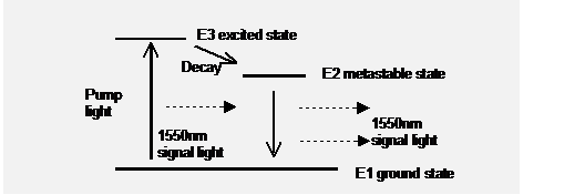
Figure 3-6 EDFA energy level diagram
When high-energy pump lasers are used to excite the EDF, lots of bound electrons of the erbium ions are excited from the basic state to the high energy level E3. However, the high energy level is not stable and erbium ions are soon dropped to the metastable state E2 via a non-radiation decay process (i.e. no photon is released). E2 level is a metastable energy band on which particles' survival span is relatively long. Particles excited by the pump light continuously gather on this level in the form of nonradiative transition. Thus, inverse distribution of the particle number is achieved. When an optical signal with the wavelength of 1550nm passes through this erbium-doped fiber, particles in the metastable state are transited to the basic state via stimulated radiation and generate photons identical to those in the incident signal light. This greatly increases the quantity of photons in the signal light, i.e. implementing the function of continuous amplifying the signal light transmitted in the EDF.
In DWDM systems, there are more and more optical channels to be multiplexed, and there are more and more optical amplifiers needed to be in serial connection. This requires that a single amplifier occupy a wider and wider bandwidth.
However, EDFA based on ordinary pure silicon optical fiber has a very narrow flat gain region only between 1549 and 1561nm, a range of approximately 12nm. And the gain fluctuation between 1530 and 1542nm is very large, up to about 8dB. When the channel arrangement of the DWDM system exceeds the flat gain region, channels near 1540nm will suffer severe signal-to-noise deteriaration and normal signal output can't be guaranteed.
To solve the above-mentioned problem and adapt to the development of DWDM systems, a gain flattened EDFA based on aluminum-doped silicon optical fiber is developed. It greatly improves the operating wavelength bandwidth of the EDFA and suppresses gain fluctuation. With the currently mature technology 1dB gain flattened range can be achieved which almost expands to the whole erbium pass-band (1525nm~1560nm), basically solving the problem of gain unflatness of ordinary EDFA. Figure 2-7 compares the gain curves of non-aluminum-doped EDFA and aluminum-doped EDFA.
Technically, the range of 1525nm~1540nm in EDFA gain curve is called blue band area and the range of 1540nm ~1565nm is called red band area. Generally, the red band area is preferred when the transmission capacity is less than 40Gbit/s.

Figure 3-7 Improvement of EDFA gain curve flatness
& Technical details:
Performance comparison between EDFA gain unflatness and flatness is given in Figure 3-8.
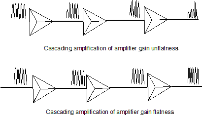
Figure 3-8 Diagram of EDFA gain flatness
EDFA gain-locking is an important issue because the WDM system is a multi-wavelength working system. When signals of certain wavelengths are lost , their energy will be transferred to those unlost signals due to gain competition, thus the power of other wavelengths increases. At the receiving end, abrupt increase of the electrical level may result in error codes. In limiting case, if seven out of the eight wavelengths are lost, all the energy will concentrate to the one wavelength left and its power may be up to about 17dBm. This will result in strong nonlinear effects or receiving power overload of the receiver, and this will also cause lots of error codes.
There are many gain-locking technologies for EDFA. One typical method is to control the gain of the pump light source. The internal monitoring electric circuit of the EDFA controls the output of the pump source by monitoring the input-output power ratio. When some signals of the input wavelengths are lost, the input power will decrease and the output-input power ratio will increase. Via the feedback circuit, the output power of the pump source will be reduced in order to keep the gain (output/input) of the EDFA unchanged. Hence, the total output power of the EDFA is reduced and the output signal power is kept stable, as illustrated in Figure 3-9.
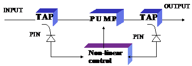
Figure 3-9 Gain-locking technology of controlling the pump light source
Furthermore, there is a saturation wavelength method. At the transmit end, in addition to the eight operating wavelengths, the system sends another wavelength as the saturation wavelength. In normal cases, the output power of this wavelength is very small. When some line signals are lost, the output power of the saturation wavelength will automatically increase in order to compensate the energy of the lost wavelengths and maintain the output power and gain of the EDFA to be constant. When the multi-wavelength line signals are restored, the output power of the saturation wavelength will correspondingly decrease. This method directly controls the output of the saturation wavelength laser, so its speed is faster than controlling the pump source.
& Technical details:
Performance comparison between gain-locking EDFA and non-gain-locking EDFA
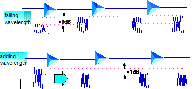
Figure 3-10 Gain variation diagram of no-gain-locking EDFA dropping and adding wavelengths
Figure 3-11 Gain variation diagram of gain-locking EDFA dropping and adding wavelengths
Its working wavelength is consistent with the minimum attenuation window of the single mode optical fiber.
High coupling efficiency. As a fiber amplifier, it can be easily coupled with the transmission fiber.
High energy conversion efficiency. The core of EDF is smaller than that of transmission fiber, signal light and pumping light are transmitted in EDF at the same time, highly centralizing the light energy. This results in a thorough interaction between the light and the gain medium Er ion, and higher light energy conversion efficiency if added with EDF of appropriate length.
High gain, low noise figure, large output power and minimum cross-talk.
Stable gain characteristics: EDFA is insensitive to temperature and polarization independence
Gain characteristic independent to system bit rate and data format.
EDFA is an indispensable key component in high capacity DWDM systems.
The gain wavelength range is fixed: the energy level difference between the energy levels of Er ion confines the working wavelength range of EDFA to a fixed 1550nm window. This is also the limitation of rare mental doped fiber amplifiers. For instance, Praseodymium doped fibers can only work on 1310nm window.
Gain bandwidth unflatness: EDFA has a wide gain bandwidth, but its gain spectrum is not flat. Special measures must be adopted in WDM system applications in order to flatten the gain of EDFA.
Optical surge problem: EDFA can enlarge the input optical power rapidly. However, since its dynamic gain changes slowly, optical surge will occur at the moment when the input signal power jumps, i.e. a peak occurs to the output optical power. The optical surge phenomenon is especially obvious in the case of EDFA cascading. The peak power can be up to a few watts and is possible to damage the O/E converter and the end surface of the optical connector.
In normal fiber system, the optical power is not high, and the fiber is characteristic of linear transmission. When very high optical power is injected into optical fiber---non-linear optical medium, the pumping light of high energy (shorter wavelength) scatters and shifts a small portion of incident power to the lowering light of another frequency. The frequency lowering scale is determined by the vibration mode of the medium. Quantum mechanics describes the phenomenon as that a photon of incident light is scattered by a molecule into another photon of lower frequency and the molecule implements its transition between vibration states. The incident photons are called pumping light, and the frequency-shifting photons of lower frequency are called stokes wave. Normal Raman scattering needs very high laser power. However, in fiber communication, the diameter of the core of monomode optical fiber as a non-linear medium is very small (generally under 10μm). As a result, the monomode optical fiber can limit the interaction between high-intensity laser field and medium in a quite small section and thus increases the optical power intensity of incident optical field. In low attenuation fiber, the interaction between the optical field and the medium can keep for a long distance, allowing for adequate energy coupling in the meantime, and for the use of stimulated Raman scattering in fiber.
Experiments prove that quartz fiber has wide SRS gain spectrum and a wide gain peak around a frequency 13THz lower than that of the pumping light. If a weak signal and a strong pumping light wave are transmitted through the fiber at the same time, and the wavelength of the weak signal is set within the Raman gain bandwidth of the strong pumping light, the weak signal can be amplified. Such SRS-based OA is call Raman optical amplifier. Raman optical amplifiers gain is the switch gain, that is, the difference between the output power when the amplifier is on and that when the amplifier is off.
Raman optical amplifier has three outstanding features:
Its gain wavelength is determined by the pumping light wavelength. Theoretically, it can produce signal amplification of any wavelength if the pump source wavelength is proper, as illustrated in Figure 3-12, in which the dotted lines are the gain spectrum of the three pump sources. This feature enables Raman fiber amplifiers to amplify in the wavelength range beyond EDFA. The usage of multiple pump sources can also get much wider gain bandwidth than that of EDFA (Being limited by energy level transition mechanism, EDFA has a gain bandwidth of 80nm only.) Therefore, it is irreplaceable in the development in the whole low attenuation region (1270nm 1670nm) of the fiber.

Figure 3-12 Raman gain spectrum of multiple pumps
The gain medium is the transmission fiber itself. This enables Raman fiber amplifiers to amplify optical signals online and constitute distributed amplification, and thus implement long-distance trunk-free transmission and remote pumping. It is especially suitable for cases disallowing repeaters, e.g. sea fiber-optic cable communication. As the amplification is distributed along the fiber instead of centralized in a section, the signal light power is comparatively low along the fiber, thus reducing the interference from non-linear effect, especially FWM effect.
Low noise fact. When it is used together with ordinary EDFA, it will largely decrease the system noise figure and increase the transmission span.
l The maximum optical power electrical level of single channel or multiple channel fiber is +17dBm or +20dBm. The optical joint and optical connector should be kept clean.
l There must be obvious safety warning signs on OA to ensure personal safety. When the fiber is disconnected, the pump source should automatically shut down or decrease the EDFA output power down to firm power.
l The service life of the optical component (pump source) of OA should be at least 300,000 h.
Wavelength division multiplexing components, that is, optical multiplexer and optical demultiplexer, are the core parts in wavelength division multiplexing systems. All of which are actually optical filters, and their performance determines that of the whole system to a great extent,. as illustrated in Figure 3-13. Optical multiplexer is mainly used to combine multi-signals into a single fiber for transmission; optical demultiplexer is mainly used to separate multiple wavelength signals transmitted in a single fiber. The performance of WDM systems depends on the WDM components. The requirements of which are enough channels, little insertion loss, large crosstalk attenuation and wide pass band range.
Theoretically, optical multiplexer and optical demultiplexer are the same, only differentiated by the directions of input and output.

Figure 3-13 DWDM components
The performance of wavelength division multiplexing components used in WDM systems meets the requirements of ITU-T G.671 and the relevant recommendations.
There are many kinds of optical wavelength division multiplexers, approximately including four types: interferometric optical filter, fiber coupler, fiber grating and arrayed waveguide grating (AWG).
Optical grating type wavelength division multiplexer, a kind of angular dispersion type component, employs the angular dispersion component to separate and combine optical signals of different wavelengths. The most prevalent diffraction grating is made by depositing epoxy resin on a glass substrate and then making grating lines on the epoxy resin, forming the reflective-type blazed diffraction grating. When the incident light reaches the optical grating, the optical signals with different wavelengths are reflected in different angles due to the angular dispersion function of the grating. Then these signals are converged to different output optical fibers via lenses in order to implement wavelength selection function. The inverse process is also correct, as shown in Figure 3-14. The advantage of the blazed optical grating is high-resolution wavelength selection function, which can separate most energy of specific wavelength from other wavelengths and focus it in centralized directions.
The blazed grating type filter has excellent wavelength selectivity and can reduce the wavelength spacing to about 0.5nm. Moreover, the grating type component works in parallel and its insertion loss doesn't increase with the number of wavelengths multiplexed, hence acquiring large number of multiplexing channels. At present, 131 0.5nm-spacing wavelengths can be multiplexed at good isolation. For a wavelength spacing of 1nm, the isolation is up to 55dB. The disadvantage of blazed grating is relatively large insertion loss, generally as high as 3~8dB. Moreover, it is very sensitive to polarization and its optical channel bandwidth-to-spacing ratio is not satisfactory. Therefore the optical spectrum utilization is low and the wavelength fault-tolerance requirement for the light source and the wavelength division mutiplexer component is relatively high. Additionally, its temperature drift varies with the thermal expansion coefficient and refractive index of the material. Typically, the component temperature shift is approximately as high as 0.012nm/C. If temperature control measures are adopted, the temperature shift can be reduced to 0.0004nm/C, making it necessary and feasible to adopt temperature control measures.

Figure 3-14 Principle of blazed optical grating wavelength division mutiplexer
This optical grating requires high manufacturing accuracy and is not suitable for mass production. Hence, it is generally applied in experimental scientific research.
Except for the above traditional optical fiber component, the manufacturing technology for optical fiber Bragg grating filter is getting more sophisticated. It is manufactured employing the interference of high power ultraviolet light beams to form periodic variation of refractive index at the optical fiber core. The accuracy can be up to 10000 lines per centimeter, as shown in the following figure. Fiber Bragg grating can be feasibly designed and manufactured at low cost. It has very low insertion loss and stable temperature characteristic. Its filtering characteristic is flat inband and very steep out-of-band (rolling slope is better than 150dB/nm and out-of-band suppress ratio is up to 50dB). This component can be directly melted with the optical fiber of the system. So it can be fabricated into band-pass or band-stop filter with small channel spacing. At present, it is extensively applied in DWDM system.

Figure 3-15 Optical fiber Bragg grating filter
However this kind of optical fiber grating has relatively narrow wavelength range, confining it to single wavelength. The benefit it brings forth is that the filters can be added or removed according to the number of wavelength used, allowing flexible applications.
Dielectric film filter type wavelength division multiplexer is a kind of core interactive wavelength division multiplexer consisting of dielectric film (DTF). DTF interference filter is composed of tens of dielectric films of different materials, different refractive indexes and different thickness combined according to design requirements. Each film layer is 1/4 wavelength in thickness. Layers of high refractive index and low refractive index are alternatively overlapped. When the light incidents on the high refractive layer, the reflected light has no phase shift. However, when the light incidents on the low refractive layer, the reflected light undergoes a 1800 phase shift. Since the layer thickness is 1/4 wavelength (900), the light reflected by the low refractive layer undergoes a 3600 phase shift and in-phase superposes with the light reflected by the high refractive layer. Thus, reflected lights of the layers superpose near the central wavelengths and form intensive reflected light at the front-end surface of the filter. In the highly backward reflecting area, the reflected light suddenly decreases and most light becomes transmitted light. Accordingly, the film interference type filter can be made to band pass certain wavelength range and band stop the other wavelength range, forming the required filter characteristics. The structural principle of the film interference type filter is shown in the following figure.
The main features of dielectric film filter wavelength division multiplexer are as follows: miniaturization and structural stability of the component can be implemented via design, the signal pass-band is flat and polarization-independent, and its insertion loss is low and channel isolation is good. The disadvantage is that the limited number of channels. The specific characteristics are related to its structure. For instance, if the film filter type wavelength division multiplexer is made of soft materials, its wavelength may be changed under the environmental influence because the filter can easily absorb moisture. When employing hard dielectric film material, the temperature stability is better than 0.0005nm/C. Additionally, this component has relatively long design and manufacturing process and low output of production. And if epoxy resin is used along the light path, it is hard to achieve high isolation and narrow bandwidth.
In wavelength division multiplexing systems, when only 4 to 16 wavelengths are involved, this type of wavelength division multiplexing component is relatively ideal.

Figure 3-16 Principle of film interference filter type de-multiplexer
There are two types of optical fiber coupler. The extensively used one of which is fused biconical tapered coupler, i.e. drawing multiple fibers under hot-melt condition to form a cone and slightly twisting and fusing them together. Because the cores of different fibers are extremely close to each other, the required coupling power can be obtained via evanescent wave coupling on the conical region. The second type of coupler removes part of cladding of the optical fiber by grinding and polishing, leaving only a thin cladding layer. Then two optical fibers processed via the same method are butt jointed and coated with a layer of index matched solution between them. Thus the two fibers can couple via the evanescent wave in the cladding and obtain the expected coupling power. Fused conical type wavelength division multiplexing component is simple to manufacture and is extensively applied.
Integrated optical waveguide type wavelength division multiplexer is a plane waveguide component based on optical integration technology. The typical manufacturing process is to deposit a thin layer of silica glass on the silicon substrate, and form the expected pattern by utilizing photetch and etch. This component supports integration manufacture and has great application prospective in future access networks. Moreover, except for wavelength division multiplexer, it can be fabricated into matrix structure to add/drop optical signal channels (OADM). Therefore it will become a preferred option for implementing optical switching in future optical transport networks.
A typical component which uses integrated optical waveguide
wavelength division multiplexer is Arrayed Waveguide Grating (AWG) optical
multiplexer/de-multiplexer manufactured by NTT Company,

Figure 3-17 Principle of AWG wavelength division multiplexer
Table 3-1 Comparison of various wavelength division multiplexing components
|
Component type |
Mechanism |
Mass production |
Channel spacing (nm) |
Number of channels |
Noise(dB) |
Insertion loss (dB) |
Main disadvantages |
|
Diffractive grating type |
Angular dispersion |
Common |
0.5~10 |
131 |
-30 |
3~6 |
Temperature sensitive |
|
Dielectric film type |
Interference/ absorption |
Common |
1~100 |
2~32 |
-25 |
2~6 |
Small number of channels |
|
Fusible cone type |
Wavelength dependent |
Relatively easy |
10~100 |
2~6 |
-(10~45) |
0.2~1.5 |
Small number of channels |
|
Integrated optical waveguide type |
Plane waveguide |
Easy |
1~5 |
4~32 |
-25 |
6~11 |
Large insertion loss |
Wavelength division multiplexing components are important in wavelength division multiplexing systems. In order to insure the performance of the wavelength division multiplexing systems, the following basic requirements to optical multiplexing components are needed: low insertion loss, large isolation, flat in band, steep insertion loss variation out band, good temperature stability, large number of multiplexing channels and small size.
The optical multiplexer of WDM system can be implemented via various technologies. At present, there are two commonly used types of 16-channel and 32-channel optical multiplexer, integrated optical waveguide type and dielectric film filter type. Their relevant parameters should meet optical multiplexer parameters requirements in Table 3-2.
Table 3-2 Requirements of the optical multiplexer parameters
|
Item |
Unit |
16-channel index |
32-channel index |
|
Insertion loss |
DB |
<10 |
<12 |
|
Reflection coefficient |
DB |
>40 |
>40 |
|
Operating
|
nm |
1548-1561 |
1530-1561 |
|
Polarization dependence loss |
DB |
<0.5 |
<0.5 |
|
Adjacent channel isolation |
DB |
>22 |
>22 |
|
Non-adjacent channel isolation |
DB |
>25 |
>25 |
|
Maximum difference of each channel insertion loss |
DB |
<2 |
<3 |
The optical demultiplexer of WDM system can be implemented via various technologies. At present, there are three commonly used types of 16-channel and WDM system optical demultiplexer, optical fiber Bragg grating type, dielectric film filter type, and integrated optical waveguide type. Their relevant parameters should meet the requirements in Table 3-3.
Table 3-3 Requirements of the optical demultiplexer parameters
|
Item |
Unit |
16-channel index |
32-channel index |
|
Channel spacing |
GHz |
100 |
100 |
|
Insertion loss |
DB |
<8 |
<10 |
|
Reflection coefficient |
nm |
40 |
40 |
|
Adjacent channel isolation |
DB |
>25 |
>25 |
|
Non-adjacent channel isolation |
DB |
>25 |
>25 |
|
Polarization dependence loss |
DB |
0.5 |
0.5 |
|
Maximum difference of each channel insertion loss |
DB |
<2 |
<3 |
|
Temperature characteristics |
nm/ |
* |
* |
|
-1dB bandwidth |
nm |
>0.2 |
>0.2 |
|
-20dB bandwidth |
nm |
* |
* |
In SDH system, the network administrator can manage and monitor network equipment via the overhead bytes in SDH frame structure (such as E1, E2, D1-D12), no matter TM, ADM or REG. Differed from SDH system, line amplifier equipment in DWDM system only performs optical amplifying to service signals. As service signals have only a light-to-light process instead of add/drop of service signals, a signal must be added to monitor the OA running status. Next, if wavelength bears overhead bytes in SDH, it is still a problem which SDH signal is to be used. Moreover, what if the service bearing in DWDM channel is otherwise service and not SDH signals? And management and monitoring information cannot depend upon services. That is why a separate channel must be used to manage DWDM equipment. A special wavelength channel can be added to DWDM system for system management, which is called the Optical Supervising Channel (OSC). For the optical line amplifiers adopting Erbium doped fiber amplifier (EDFA) technology, the gain area of EDFA is 1530 nm -1565 nm, the OSC must lie outside the available gain bandwidth of EDFA (out band OSC), being 1510 nm Coded Mark Inversion (CMI) for supervisory channel is used as the line code type.
The requirements on DWDM to optical supervisory channel are as follows:
l The optical supervisory channel doesn't limit the pump wavelength of the optical amplifier;
l The optical supervisory channel doesn't limit the distance between two line amplifiers;
l The optical supervisory channel doesn't restrict the traffic in the 1310nm wavelength;
l The optical supervisory channel is still available when the line amplifier fails.
According to the above requirements:
The wavelength of the optical supervisory channel should not be 980nm and 1480nm, for Erbium doped fiber amplifier (EDFA) uses the laser with these wavelengths as the pump source and Raman optical amplifier uses the laser with the wavelength around 1480nm as the pump source at the same time.
The wavelength of the optical supervisory channel should not be 1310nm, for which will occupy bandwidth resources of 1310 window, hindering the traffic in 1310nm window.
The receiving sensitivity for the optical supervisory channel can be set very high, so that the distance between stations will not be confined due to the power of OSC, and such distance may be the distance between optical amplifiers. Hence the optical supervisory channel needs to use low rate optical signals to insure high receiving sensitivity.
The wavelength of the optical supervisory channel is located beyond the gain area bandwidth of the optical amplifier, so that the optical supervisory channel will not be affected when the optical amplifier fails. For optical line amplifiers adopting erbium-doped optical fiber amplifier (EDFA) technology, the gain spectrum area is 1528-1610nm. Therefore, the wavelength of the optical supervisory channel must be located beyond the gain bandwidth of EDFA. Usually, the wavelength of the optical supervisory channel is 1510nm or 1625nm.
According to the recommendations of ITU-T, the optical supervisory channel of DWDM system should be completely independent of the main channel, while such independence between the two channels is embodied fully in signal flow directions. In the OTM site, the supervisory channel is combined and amplified in the sending direction before put into the main channel; while in receiving direction, the supervisory channel is separated before the main channel is pre-amplified and demultiplexed by the system. Likewise, in the OLA site, the supervisory channel is combined in the end in the sending direction; while in receiving direction, the supervisory channel is separated in the first place. As seen from the above, the supervisory channel does not take part in amplifying in the whole transmission, but it is terminated and regenerated in every site This is contrary to the main channel, as it does take part in the amplifying of the optical power in the whole process, and is not terminated and regenerated in the whole line. The wavelength division equipment only provides it with transparent optical channels.
The interface parameters for supervisory channel are shown in Table 3-4.
Table 3-4 Interface parameters for supervisory channel
|
Supervisory wavelength |
1510nm |
|
Supervisory ratio |
2Mbit/s |
|
Signal code pattern |
CMI |
|
Signal transmitting power |
(0~-7dBm) |
|
Source type Spectral characteristics |
MLM LD * |
|
Minimum receiving sensitivity |
-48 dBm |
2Mbit/s system physical interface of the supervisory channel should conform to G.703 requirements, with the frame structure and bit rate compliant to G.704 specification, as shown in Figure 3-18.
|
0 |
1 |
2 |
3 |
.. |
16 |
17 |
. |
29 |
30 |
31 |
Figure 3-18 The frame structure of supervisory channel
Time slot 0: frame synchronization byte.
There are at least 2 time slots used as the orderwire channels in a frame structure. One of which acts as the optical regenerator section service contact and can be combined in the optical amplifier repeater site, while the other acts as an orderwire between optical multiplexing bands and can be combined in the end of WDM system.
In a frame structure, there is only 1 time slot provided for users (usually the network provider), which can be combined in the optical line amplifier repeater site.
In a frame structure, there must be 4 bytes used as the DCC channel of the optical repeating band and 8 bytes as the DCC channel of the optical multiplexing band. Both are used to transmit network management information of the related WDM system Terminal Equipment has two interfaces, for orderwire and user channel respectively.
At least it must be free bytes made available for future expansion.
What are electro-absorption laser modulation scheme and M-Z modulation scheme?
How many types are there for the wavelength division multiplexer? What are their individual characteristics?
Which are the kinds of optical amplifiers? Describe gain flat control and gain lock of EDFA.
What are optical supervisory channel wavelength and supervisory rate of DWDM?
& Objective:
Learn the recommendations and relevant specifications of ITUT on WDM system.
International Telecommunications Union (ITU-T) has made significant contributions for WDM, mostly shown in the following recommendations:
ITU-T Recommendation G.652(1993) Characteristics of single-mode fiber cable
ITU-T Recommendation G0.653(1993) Characteristics of dispersion shifted single-mode fiber cable
ITU-T Recommendation G.655(1996) Characteristics of a non-zero dispersion shifted single-mode optical fiber cable
ITU-T Recommendation G.661(1993) Definition and test methods for the relevant generic parameters of optical fiber amplifiers
ITU-T Recommendation G.662(1994) Main characteristics of optical amplifier equipment and sub-systems
ITU-T Recommendation G.663(1996) Optical amplifier related transmission problems
ITU-T Recommendation G.671(1996) Requirements for passive optical components
ITU-T Recommendation G.681(1997) Functional characteristics of interoffice and long-haul line systems using optical amplifiers, including optical multiplexing
ITU-T Recommendation G.691(1997) Optical interface for single channel systems with optical amplifier SDH and STM-64 systems.
ITU-T Recommendation G.692(1998) Optical interface for multi-channel systems with optical amplifier
In order to normalize optical interface parameters, ITU-T G.692 document defines all the reference points for WDM optical transmission systems, as shown in the following figure Tx 1, Tx 2, and TxN usually refer to terminal transmitters of a system. Wavelength division multiplexer (optical multiplexer) is used in the transmitting end to merge different wavelength signal optical carriers and send them to a single fiber for transmission In the receiving end, another wavelength division multiplexer (optical demultiplexer) is used to separate these optical carriers in which different wavelengths carry different signals.
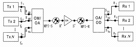
Figure 4-1 WDM optical interface reference points
The WDM system in the above figure has the following reference points:
S1Sn: The reference points on the fiber at transmitter optical output connector in channels 1n;
RM1 RMn: The reference points on the fiber at OM/OA optical input connector in channels 1n;
MPI-S: A reference point on the optical fiber just behind the OM/OA optical output connector;
S': A reference point on the optical fiber behind the optical output connector of the optical line amplifier;
R': A reference point on the optical fiber in front of the optical input connector of the optical line amplifier;
MPI-R: A reference point on the optical fiber in front of the OA/OD input optical connector;
SD1SDn: The reference points at the OA/OD optical output connector;
R1Rn: The reference points at receiver optical transmitter input connector.
l A fiber has two long wavelength and low loss windows, 1310nm window and 1550nm window. Both of which can be used to transmit optical signals, but the commonly used working wavelength range for the erbium-doped optical amplifier is 192.1-196.1THz.Therefore the working wavelength area for wavelength division multiplexing system is 192.1-196.1THz.
l Nominal central frequency refers to the central wavelength corresponding to each channel in optical wavelength division multiplexing systems Channel frequency allowed in G.692 is based on frequency and spacing series of reference frequency 193.1THz and minimum spacing 100GHz or 50GHZ.
l The standard wavelength of WDM channel has two configurations: equal spaced and unequal spaced. The unequal spaced wavelength is used to avoid the four-wave mixing effect As no obvious four-wave mixing effect has been observed in WDM systems using G.652 and G.655 fibers, G.692 document recommends the following standard wavelengths in Table 3-1 for WDM systems using these fibers.
Table 4-1 Standard central frequency
|
Standard central frequency (THz) 50 GHz Spacing |
Standard central frequency (THz) 100 GHz Spacing |
Standard central wavelength (nm) |
|
196.10 |
196.10 |
1528.77 |
|
196.05 |
|
1529.16 |
|
196.00 |
196.00 |
1529.55 |
|
195.95 |
|
1529.94 |
|
195.90 |
195.90 |
1530.33 |
|
195.85 |
|
1530.72 |
|
195.80 |
195.80 |
1531.12 |
|
195.75 |
|
1531.51 |
|
195.70 |
195.70 |
1531.90 |
|
195.65 |
|
1532.29 |
|
195.60 |
195.60 |
1532.68 |
|
195.55 |
|
1533.07 |
|
195.50 |
195.50 |
1533.47 |
|
195.45 |
|
1533.86 |
|
195.40 |
195.40 |
1534.25 |
|
195.35 |
|
1534.64 |
|
195.30 |
195.30 |
1535.04 |
|
195.25 |
|
1535.43 |
|
195.20 |
195.20 |
1535.82 |
|
195.15 |
|
1536.22 |
|
195.10 |
195.10 |
1536.61 |
|
195.05 |
|
1537.00 |
|
195.00 |
195.00 |
1537.40 |
|
194.95 |
|
1537.79 |
|
194.90 |
194.90 |
1538.19 |
|
194.85 |
|
1538.58 |
|
194.80 |
194.80 |
1538.98 |
|
194.75 |
|
1539.37 |
|
194.70 |
194.70 |
1539.77 |
|
194.65 |
|
1540.16 |
|
194.60 |
194.60 |
1540.56 |
|
194.55 |
|
1540.95 |
|
194.50 |
194.50 |
1541.35 |
|
194.45 |
|
1541.75 |
|
194.40 |
194.40 |
1542.14 |
|
194.35 |
|
1542.54 |
|
194.30 |
194.30 |
1542.94 |
|
194.25 |
|
1543.33 |
|
194.20 |
194.20 |
1543.73 |
|
194.15 |
|
1544.13 |
|
194.10 |
194.10 |
1544.53 |
|
194.05 |
|
1544.92 |
|
194.00 |
194.00 |
1545.32 |
|
193.95 |
|
1545.72 |
|
193.90 |
193.90 |
1546.12 |
|
193.85 |
|
1546.52 |
|
193.80 |
193.80 |
1546.92 |
|
193.75 |
|
1547.32 |
|
193.70 |
193.70 |
1547.72 |
|
193.65 |
|
1548.11 |
|
193.60 |
193.60 |
1548.51 |
|
193.55 |
|
1548.91 |
|
193.50 |
193.50 |
1549.32 |
|
193.45 |
|
1549.72 |
|
193.40 |
193.40 |
1550.12 |
|
193.35 |
|
1550.52 |
|
193.30 |
193.30 |
1550.92 |
|
193.25 |
|
1551.32 |
|
193.20 |
193.20 |
1551.72 |
|
193.15 |
|
1552.12 |
|
193.10 |
193.10 |
1552.52 |
|
193.05 |
|
1552.93 |
|
193.00 |
193.00 |
1553.33 |
|
192.95 |
|
1553.73 |
|
192.90 |
192.90 |
1554.13 |
|
192.85 |
|
1554.54 |
|
192.80 |
192.80 |
1554.94 |
|
192.75 |
|
1555.34 |
|
192.70 |
192.70 |
1555.75 |
|
192.65 |
|
1556.15 |
|
192.60 |
192.60 |
1556.55 |
|
192.55 |
|
1556.96 |
|
192.50 |
192.50 |
1557.36 |
|
192.45 |
|
1557.77 |
|
192.40 |
192.40 |
1558.17 |
|
192.35 |
|
1558.58 |
|
192.30 |
192.30 |
1558.98 |
|
192.25 |
|
1559.39 |
|
192.20 |
192.20 |
1559.79 |
|
192.15 |
|
1560.20 |
|
192.10 |
192.10 |
1560.61 |
Which are the ITU-T recommendations involved for WDM part?
What is the absolute reference frequency for optical wavelength division multiplexing systems? What is their channel spacing?
|
Abbreviations |
Explanation |
Descriptions |
|
ADM |
Add and Drop Multiplexer |
Add/Drop Multiplexer |
|
AGC |
Automatic Gain Control |
Auto Gain Control |
|
ALC |
Automatic Level Control |
Auto Power Control |
|
ALS |
Automatic Laser Shutdown |
Automatic laser shutdown |
|
APD |
Avalanche Photo Diode |
APD |
|
APR |
Automatic Power Reduction |
Automatic Power Reduction |
|
ASE |
Amplified Spontaneous Emission |
Amplified Spontaneous Emission |
|
AWG |
Arrayed Waveguide Grating |
Arrayed Waveguide Grating |
|
BA |
Booster Amplifier |
Booster Amplifier |
|
BER |
Bit Error Ratio |
Bit Error Ratio |
|
CLNS |
Connectionless Network Layer Service |
Connectionless Layer Network Service |
|
CMI |
Coded Mark Inversion |
Coded Mark Inversion |
|
CRC |
Cyclical Redundancy Check |
Cyclic Redundancy Check |
|
CSES |
Continuous Severely Errored Second |
Consecutive Severely Errored Second (CSES) |
|
CWDM |
Coarse Wavelength Division Multiplex |
Coarse Wavelength Division Multiplexing |
|
DCC |
Data Communication Channel |
Data Communication Channel |
|
DCF |
Dispersion Compensation Fibre |
Dispersion Compensation Fiber |
|
DCM |
Dispersion Compensation Module |
Dispersion compensation module |
|
DCN |
Data Communication Network |
Data Communication Network |
|
DDN |
Digital Data Network |
Digital Data Network |
|
DFB |
Distributed Feedback |
Distributed Feedback |
|
DSP |
Digital Signal Processing |
Digital Signal Processing |
|
DWDM |
Dense Wavelength Division Multiplexing |
DWDM |
|
ECC |
Embedded Control Channel |
Embedded Control Channel |
|
EDFA |
Erbium-Doped Fiber Amplifier |
Erbium-Doped Fiber Amplifier |
|
ETSI |
European Telecommunication Standards Institute |
ETSI |
|
FEC |
Forward Error Correction |
Forward Error Correction |
|
FIFO |
First In First Out |
First-In First-Out |
|
GE |
Gigabit Ethernet |
Gigabit Ethernet |
|
GUI |
Graphic User Interface |
Graphic User Interface |
|
IEEE |
Institute of Electrical and Electronic Engineers |
International Institute for Electrical and Electronic Engineers |
|
ITU-T |
Telecommunication Sector |
International Telecommunication Union-Telecommunication Sector |
|
LA |
Line Amplifier |
Line Amplifier |
|
LAN |
Local Area Network |
Local Area Network |
|
LCN |
Local Communication Network |
LCN |
|
LCT |
Local Craft Terminal |
LMT |
|
LD |
Laser Diode |
Laser Diode |
|
MCF |
Message Communication Function |
Message Communication Function |
|
MD |
Mediation Device |
Medium Device |
|
MPI-R |
Main Path Interface at the Receiver |
Main Path Interface at the Receiver |
|
MPI-S |
Main Path Interface at the Transmitter |
Main Path Interface at the Transmitter |
|
NE |
Network Element |
Network Element |
|
NF |
Noise Figure |
Noise Figure |
|
NRZ |
Non Return to Zero |
Non Return to Zero |
|
OA |
Optical Amplifier |
OA |
|
OADM |
Optical Add and Drop Multiplexer |
Optical Add and Drop Multiplexer |
|
OD |
Optical Demultiplexing |
Optical Demultiplexing |
|
ODF |
Optical Distribution Frame |
Optical Distribution Frame |
|
Overhead Processor Unit |
Overhead Processing |
Overhead processing |
|
OLA |
Optical Line Amplifier |
Optical Line Amplifier equipment |
|
|
Optical Multiplexing |
Optical Multiplexing |
|
OS |
Operations System |
Operation system |
|
OSC |
Optical Supervisory Channel |
Optical Supervisory Channel |
|
OSI |
Open Systems Interconnection |
Open Systems Interconnection |
|
OSNR |
Optical Signal/Noise Ratio |
Optical signal-to-noise ratio |
|
OTM |
Optical Terminal Multiplexer |
Optical Terminal Multiplexing Equipment |
|
OTU |
Optical Transponder Unit |
Optical Transponder Unit |
|
PA |
Pre-amplifier |
Preamplifier |
|
PDH |
Plesiochronous Digital Hierarchy |
Plesynchronous Digital Hierarchy |
|
PIN |
Positive Intrinsic Negative |
Positive Intrinsic Negative |
|
PON |
Passive Optical Network |
Passive Optical Network |
|
SCC |
System Control & Communication |
System control and communications |
|
SDH |
Synchronous Digital Hierarchy |
Synchronous Digital Hierarchy |
|
SNCP |
Subnetwork Connection Protection |
SNCP (Subnetwork Connection Protection) |
|
STM |
Synchronous Transport Module |
Synchronous Transport Module |
|
TCP/IP |
Transport Control Protocol/Internet Protocol |
Transmission Control Protocol/Internet Protocol |
|
TMN |
Telecommunication Management Network |
Telecom Management Network(TMN) |
|
TTL |
Transistor-Transistor Logic |
Transistor-Transistor Logic |
|
WDM |
Wavelength Division Multiplexing |
WDM |
|
WS |
Work Station |
Workstation |
|
Politica de confidentialitate | Termeni si conditii de utilizare |

Vizualizari: 3615
Importanta: ![]()
Termeni si conditii de utilizare | Contact
© SCRIGROUP 2025 . All rights reserved