| CATEGORII DOCUMENTE |
| Bulgara | Ceha slovaca | Croata | Engleza | Estona | Finlandeza | Franceza |
| Germana | Italiana | Letona | Lituaniana | Maghiara | Olandeza | Poloneza |
| Sarba | Slovena | Spaniola | Suedeza | Turca | Ucraineana |
Test generation for synchronous sequential circuits is a hard and complicated task. Varied in complexity methods for test generation are being developed for years. The present methods can be divided into four categories. Methods of the first category use the ways of branches and limits for test attainment; such ways are called deterministic. Methods of the second category use fault modeling in order to route the search for test sets to the chosen faults. The test generation procedures based on the genetic optimization belongs to this category as well. The third category uses particular determinate properties of test sequences; such properties are used in selecting such input sequences that have equal properties and that are suitable for test sequences. Methods of the fourth category are based on the pseudo-random generators or generators with a special purpose that generate effective test sets. These methods are usually used in installing BIST in order to reduce the amount of additional equipment. As well combinations of methods from various categories are used in order to improve test sequences.
The test generation method presented in this section is based on the sequential circuit iterative logic array model (IM) [1]. Test generation is performed for an iterative model that consists of the sequential circuit combinational logic copies array using the regular combinational ATPG. Further this test is being adapted for the sequential circuit.
Classical iterative logic array model
An iterative model of the synchronous sequential circuit imitates its functioning expanded time-wise. When flip-flops values returns back to the circuit from the synchronous sequential circuit with each synch-signal then in the iterative model they move to the other copy of combinational logic (Figure 5.1).
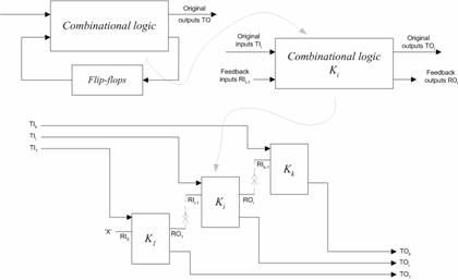
Figure 5.1. Creating IM
Having such an iterative model test sets are generated by the help of the combinational ATPG. The adjustment of these sets to the sequential circuit proceeds in such a way: sets are disintegrated into smaller sets which number corresponds to the copies number. Smaller sets are already used for testing the sequential circuit by giving them in different synch-signal periods.
A test generation approach for sequential circuits based on the iterative logic array model is described in [1]. We will shortly remind the main features of this approach. Each component of the state vector can have one of five values, namely . If a test exists, 0 or 1 can replace the X value, hence only four values need to be considered. It is clear that in testing a circuit it is never necessary to enter some state twice, therefore each state vector can be restricted to be unique, and there are 4n such unique states, where n is the number of state variables. The test generation procedure given in [1] consists of the following three steps:
Set k to 1 for the number of copies (combinational cells) of the iterative circuit model. Set dont-care value X for all state variables of the first copy.
Construct the k-iterative array model of the circuit.
Apply the combinational ATPG for a k-iterative array model of the circuit. If no test vectors are found for undetected faults, increment k by one and repeat (2). Terminate when k>4n. If no test vectors are found for some faults, the circuit is redundant.
Case study
Consider the s27 ISCAS89 benchmark circuit shown in Figure 5.2(a). Figure 5.2(b) shows 4-iterative array model of this circuit. A combinational cell of s27 is shown in Figure 5.3. Figure 5.4 shows VHDL description, which is very easily adjustable for a number of cells. Combinational ATPG (SYNOPSYS) generated 9 test vectors for 4-iterative array model of the circuit s27. Each test vector is of length 4* PI=16. In order to apply these test vectors to initial circuit s27, test vectors must be folded in test sequences of four test vectors of length equal to PI each. VeriFault (CADENCE) confirmed that all stuck-at faults are detected by test sequences derived from generated 9 test vectors for 4-iterative array model of s27. As we can see, the capabilities of VHDL language give an opportunity simply to apply combinational ATPG for test generation of sequential circuits.
a)
b)
Figure 5.2. s27 circuit (a) and 4-iterative array model (b)
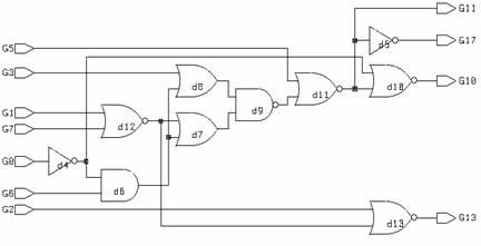
Figure 5.3. Combinational cell of the circuit s27
-- s27 circuit 4-iterative combinational model
library IEEE;
use IEEE.std_logic_1164.all;
entity s27 is
generic(N: INTEGER := 4 ; K: INTEGER:=3);
port( G0,G1,G2,G3 : in std_logic_vector(N-1 downto 0);
G17 : out std_logic_vector(N-1 downto 0));
end s27;
architecture gen_vhdl of s27 is
component dffx
port( q : out std_logic;
clk, d : in std_logic);
end component;
component s27k
port( G0,G1,G2,G3 : in std_logic ;
G17 : out std_logic;
G5,G6,G7 : in std_logic ;
G10,G11,G13 : out std_logic);
end component;
signal GR :std_logic_vector((N+1)*K-1 downto 0);
signal LogicX,Logic0,Logic1 : std_logic;
begin
GR(I)<=LogicX;
end generate
u: s27k port map ( G0=>G0(I),G1=>G1(I),G2=>G2(I),G3=>G3(I),
G17=>G17(I),
G5=>GR(I*K),G6=>GR(I*K+1),G7=>GR(I*K+2),
G10=>GR((I+1)*K),G11=>GR((I+1)*K+1),G13=>GR((I+1)*K+2));
end generate
x_generator : dffx port map( q => LogicX, clk => Logic0, d => Logic0);
Logic0 <= '0';
end gen_vhdl;
Figure 5.4. VHDL description of the k-iterative array model of s27
The results of our experiments for circuit s208 with resetable Flip Flops are reported in Table 5.1. The test generation time grows rapidly by increasing the number of copies of the iterative model for the circuit. However, this increase of computation time isnt as hopeless as in the case of test generation by means of sequential ATPG. The results of experiments in Table 5.1 demonstrate that sequential ATPG allows getting fault coverage, which corresponds to the fault coverage level for 16-32 copies for iterative array model. The fault coverage permanently becomes higher by increasing the number of copies of the iterative circuit model up to 256. The fault coverage remains the same in case of 320 copies. This means that computation capabilities in this case are exhausted. Computation time for one fault on the average presented in the last row of Table 5.1 grows very rapidly. Figure 5.5 demonstrates how the faults are detected in each copy.
Table 5.1
|
Number of copies (cells) | ||||||||||
|
Max. fault coverage of one cell (%) | ||||||||||
|
Max. amount of detected faults in one cell (Synopsys) | ||||||||||
|
Generation time (s) | ||||||||||
|
CPU time for abandon faults (%) | ||||||||||
|
Fault coverage Verifault -% | ||||||||||
|
Number of test sequences | ||||||||||
|
Computing time (s) required for one fault on the average |
Figure 5.5. Number of detected faults among cells of logic array model of circuit s208
Search Management
The number of copy for highest fault detection according to the curve provided in Figure 5.5 can be selected. Unfortunately, the fault injection in one copy only doesnt allow getting the same fault coverage. This means that some faults were marked as detected by test generation for faults of others copies. Therefore, the selection of a copy for fault injection is problematic enough. However, the test generation time for one fault on the average is smaller as compared to average test generation time by fault injection in each copy, but finally the fault coverage is higher in case of classical logic array model. Careful selection of the number of copy for fault selection gives an opportunity to get the same fault coverage as in the case of test generation by fault injection in all copies. ( Table 5.2 and Table 5.3)
Table 5.2
|
Circuit |
Faults |
Fault coverage |
CPU time |
Sequences |
||
|
Total |
Detected |
Undetected |
Synopsys |
(s) | ||
|
S27 | ||||||
|
S208(R ) | ||||||
|
S298 | ||||||
|
S344 | ||||||
|
S420 (R ) | ||||||
|
S444 | ||||||
|
S641 | ||||||
|
S820 | ||||||
|
S832 | ||||||
|
S838(R ) | ||||||
|
S9234(R ) | ||||||
Table 5.3
|
Circuit |
Faults |
Fault coverage |
CPU time |
Sequences |
||
|
Total |
Detected |
Undetected |
Synopsys |
(s) | ||
|
S27 | ||||||
|
S208(R ) | ||||||
|
S298 | ||||||
|
S344 | ||||||
|
S420 (R ) | ||||||
|
S444 | ||||||
|
S641 | ||||||
|
S820 | ||||||
|
S832 | ||||||
|
S838(R ) | ||||||
|
S9234(R ) | ||||||
The test generation results in case of fault injection in one and in all copies are compared with the results of famous sequential ATPG HITEC [2]. We can see (Table 5.4) that the use of the iterative logic array model can compete with this industrial ATPG and in some cases can give better results.
Table 5.4
|
Circuit |
HITEC |
Faults in all copies |
Faults in the one copy |
|||
|
Fault coverage |
CPU time |
Fault coverage |
CPU time |
Fault coverage |
CPU time |
|
|
S27 | ||||||
|
S208(R ) | ||||||
|
S298 | ||||||
|
S344 | ||||||
|
S420 (R ) | ||||||
|
S444 | ||||||
|
S641 | ||||||
|
S820 | ||||||
|
S832 | ||||||
|
S838(R ) | ||||||
|
S9234(R ) | ||||||
Circuit description language VHDL gives an opportunity easy to generate logic array model of sequential circuit and practically to use combinational ATPG for test generation of sequential circuits. The iterative logic array model by introducing faults in one or in all copies of the circuit allows in most cases to get higher fault coverage as compared to the famous test generation tool HITEC. At that time the iterative logic array model creates new possibilities for effective test generation, because enables easy to manage the test generation process.
Test development for sequential circuits can be tedious and time-consuming. Automatic test pattern generation (ATPG) tools have attempted to address this problem. ATPG for a given target fault consists of two phases. Fault activation phase establishes a signal value at the fault site opposite to that produced by the fault. Fault propagation phase propagates the fault effect forward by sensitizing a path from the fault site to a primary output.
The efficiency of ATPG is largely determined by decision-making and backtracking strategies. Decision-making takes place during justification, the process of assigning values to gate inputs when the logic value of the gate output is known. The process is recursive and ends when the primary inputs are reached. Backtracking takes place as a result of implication, the process by which new values assigned during justification uniquely determine the values on other signals. Because a circuit has reconvergent fan-outs, new signal values during implication can conflict with the values of the signals assigned earlier [3].
One of the complicating factors for ATPG is the existence of illegal states, i.e., states that cannot be reached during the normal operation of a circuit. A sequential test generator may waste a lot of time trying to justify illegal states. This often occurs when the target fault is undetectable; a situation recognized only when the exhaustive search for a test sequence terminates without finding any. This search process relies on backtracking to recover from dead-end situations. A dead-end is characterized by encountering either an inconsistency (conflicting assignments) or a loop of illegal states.
Determining legal and illegal states is an efficient pre-processing technique of ATPG that significantly reduces computational complexity [4]. For example, knowing that a state is illegal allows for an ATPG algorithm to avoid an expensive and futile state justification process. Also, any fault whose detection requires the circuit to be in an illegal state can be immediately identified as undetectable.
In this section, we describe
the forward and backward state search procedures and a procedure for
identifying exact collection of the legal states. All procedures are
based on applying of the conventional test pattern generator for stuck-at
faults of combinational circuits. The combinational test generator is managed
by the state sets implemented as
The suggested procedures rely on the combinational part of a sequential circuit only what is very important for efficiency of practical computation. The goal of the experiments is to compare the cardinality of the exact legal states collection with the collection of reachable states identified on the iterative logic array model and to establish what influence it has for identifying of undetectable faults
Preliminaries
A state variable corresponds to the flip-flop of sequential circuit. A state variable has the fixed value 1 or 0 after powering up a circuit. The powering up collection W consists of all possible states after powering up a sequential circuit.
Definition 1: A state variable v is settable if there exists an input sequence which sets v to the fixed value starting from any state of powering up collection W.
Definition 2: A state variable is unsettable if it is not settable.
Definition 3 A sequential circuit is synchronizable if all state variables are settable.
Definition 4 A sequential circuit is non-synchronizable if not all state variables are settable.
Definition 5 A sequential circuit is partially synchronizable if some state variables are settable.
Operating of a sequential circuit typically begins by applying an initialization sequence. During this initialization phase, the output responses are usually ignored. An initialization sequence brings a circuit to the initialization state and determines a predictable behaviour. During the normal operation, the circuit always operates in some finite collections of states that satisfy the following conditions:
Any state in a collection is reachable from any other state in that collection.
No state in a collection can reach a state outside the collection.
These finite collections of states are typically referred to as the terminal strongly connected components (tSCC) of a circuit.
Definition 6 The states of tSCC are legal states
Definition 7 A state is said to be illegal if it is not legal state.
Definition 8: A tSCC is legal if there exists an initialization sequence that brings from each initial state of collection W to the state of this tSCC.
A synchronizable circuit has at most one legal tSCC. In sequential circuits undectability and redundancy have different concepts. Several different definitions for sequential undetectability and redundancy can be found in the literature. The definitions of this work are based on the definitions contained in [5, 6].
Definition 9 Initial states S and Sf are circuit states after powering up the faulty-free and faulty circuit, respectively.
Definition 10 A fault f is said to be detectable if there exists an input sequence I such that for every pair of initial states S and Sf of the fault-free and faulty circuit respectively the response Z (I, S) of the fault-free circuit to the input sequence I is different from the response Zf (I, Sf) of the faulty circuit at a specific time unit and on a specific primary output.
Note that this definition is based on a single observation time (SOT) approach [7].
Definition 11 A fault is said to be undetectable if it is not detectable.
Definition 12 A fault is partially detectable if there exists an initial state Sf of the faulty circuit and an input sequence I such that for every faultfree initial state S the response of the fault-free circuit to I, starting from S, Z (I, S) is different from the response of the faulty circuit starting from Sf, Zf (I, Sf) at a specific time unit and on a specific primary output.
A collection L of legal states and a collection Ln of illegal states can be exact (complete), enlarged and partial. The exact collection L (Ln) has all legal (illegal) states. A partial collection L (Ln) has only some of the legal (illegal) states. The exact collection L (Ln) is complementary to the exact collection Ln (L). The enlarged collection L (Ln) is complementary to the partial collection Ln (L) and includes all legal (illegal) and some illegal (legal) states. The use in ATPG of any collection L (Ln) can reduce computational complexity of test generation. However, the identification of undetectable faults relies on the use of the exact or enlarged collection L and on the use of the exact or partial collection Ln. The partial collection L and enlarged collection Ln are not applicable for identification of undetectable circuits. Figure 5.6 illustrates the relations between exact, partial and enlarged collections and their application for identification of undetectable faults.
|
All possible states of the circuit |
|||
|
Exact collection L of legal states (Identification of undetectable faults |
Exact collection Ln of illegal states (Identification of undetectable faults |
||
|
Enlarged collection L of legal states (Identification of undetectable faults |
Partial collection Ln of illegal states (Identification of undetectable faults |
||
|
Partial collection L of legal states |
Enlarged collection Ln of illegal states |
||
Figure 5.6. The relations between exact, partial and enlarged state collections
Identification of legal and illegal states
The existing approaches for identification of collections of legal L and illegal Ln states can be divided into four groups:
Methods of the group M1 for identification of the legal states rely on a forward state search of the circuit starting from a given set of reset states [8-10]. The forward state search yields the exact collection L of legal states, which can be complemented to get the exact collection Ln of illegal states. The methods require at least one legal state or initialization sequence to be known in advance. However, some circuits operate without reset.
Methods of the group M2 for identification of the legal states rely on three-valued logic simulation and on a forward state search of the circuit starting from an unknown state [11]. The use of the collection of legal states allows identifying of undetectable faults in the circuit. However, faults that are claimed as undetectable using three-valued simulation may, in fact, be testable [4].
Methods of the group M3 for identifying of the legal states rely on the iterative logic array of the circuit [6]. The forward state search starting from the all-possible initial states yields the enlarged collection L of legal states. The approach is based on so called combinational ATPG Theorems [12, 13] and on so called Pixleys outer envelope computation [14].
Methods of the group M4 for identifying of the illegal states rely on eliminating of the states without predecessors and ignoring self-loops [4]. The backward state search starting from all possible states as legal yields a partial collection Ln of illegal states. Methods dont require reset or initialization sequence.
Methods of the first two groups M1 and M2 either are restricted to the synchronizable circuits only or get an incorrect result. Methods of the last two groups M3 and M4 yield the enlarged collection of legal states. We propose a unified framework for identification legal and illegal states and a procedure for identifying legal states that doesnt require reset or initialization sequence and yields exact collection of legal states for synchronizable, partially synchronizable and non-synchronizable circuits. The procedure generalizes and accumulates the best features of the methods from all four groups.
Forward state search procedure
The iterative logic array model of a synchronous sequential circuit C consists of copies of the combinational logic of the circuit, connected in such a way that the next state variables of one copy drive the present state variables of the copy to its right [1]. Our procedures rely only on one copy of the combinational logic of the iterative logic array model.
Figure 5.7. Circuit test1
|
Input vectors |
Output vectors |
Detected faults |
|||||||||||||||||
|
a |
b |
c |
d |
e |
f |
a11, a21, a31,d 0, e 1, f1 | |||||||||||||
|
a10, b1, c 1, d 1, e 1, f 1 | |||||||||||||||||||
|
a10,a20,a30,b0,c0,d1,e0,f0 | |||||||||||||||||||
Figure 5.8. Test patterns of circuit test1
First
at all, consider how to manage search space of conventional test generator for
stuck-at faults of a combinational circuit by means of the
Let suppose all possible output vectors should be established. The conventional test generator applied to the circuit gives input and output vectors given in Figure 5.8, which detect all stuck-at faults of the circuit.
The
test generator defines three output vectors 100, 000,011. Further, these
defined output vectors must be forbidden in the output search space by means of
Figure 5.9. Circuit test1 with
The
|
Input vectors |
Output vectors |
Detected faults |
||||
|
a |
b |
c |
d |
e |
f |
|
|
a10, b1, c0, d 1, e 1, f 0 |
||||||
|
a10, a20, b0, c 1, d 1, e 0, f 1 |
||||||
Figure 5.10. Test patterns of circuit with
Test
generator defines two new output vectors 001, 010. Note that in the case of
search space restriction using
The
search space of input vectors can be restricted by
Figure 5.11. Circuit test1
with
In
this case the test generator will consider only such test vectors that have on
inputs b and c signal values 10 or 11, i.e. only vectors 010, 110, 011,111 are
permitted on the circuit inputs. The test generator would consider only such
test vectors that dont have on inputs b and c signal values 10 or 11, i.e.
vectors 010, 110, 011, 111 are forbidden on the circuit inputs, if the signal
value 0 were required on the output of
A model for identifying of the states that are reachable (that can be reached) from a given initial state for synchronous sequential circuits is shown in 5.12. All the next state variables are assumed to be observable. All the primary inputs and present state variables are assumed to be controllable. A combinational test generation procedure for single stuck-at fault model is used to generate a test for the single fault injected into combinational logic of the circuit.
A test generation procedure takes into account collection P of present and collection N of next state variables. The states in collections P and N are permitted for the present and next state variables during a search by test generation. The forward state search procedure starts from one or few initial states. At the beginning, the present state search space P consists of initial states and the next state search space N consists of all possible states. The test generation procedure produces test vectors for single faults of combinational logic of the copy. The next state variables of the output test vectors identify a collection R of states reached from the initial states. Then the collection R of reached states reduces the collection N (N: = N R) and supplements the collection F of front states (F: = F R), which is empty at the beginning of iteration (F: =).
Figure 5.12. A model for state search of a circuit.
The states in the collection F reflect the front by expansion of states. A repeated test generation for all faults of combinational logic produces new test vectors and a new collection R of the reached states, which reduces again the collection N and supplements the collection F. An iteration ends if test generation procedure returns no test vectors. This means that all reachable states are reached from the collection of states P and indicates the end of state search front. New iteration (front) of the forward state search procedure starts with collection P: = F. The iterations of the procedure terminate if test generation procedure starting from the last front collection F returns no test vectors. This means that no state can be reached from the last front collection F, and a collection complementary to N is the collection of reachable states of the circuit C. An illustration of the first and second fronts for states expansion from the initial state is given in Figure 5.13.
Figure 5.13. The fronts of initial state expansion.
A
search space of the combinational test generator for stuck-at faults is limited
by state collections P and N that are implemented using
#
#in out
1 0 1 - 1
0 1 0 - 1 1
% % % % % 0
The
synthesized
The collection of the reached states R can directly
supplement the collection P (P: = P R). In this case the number
of state search fronts cant be fixed. The Forward State Search procedure (
Build the model for state search of synchronous sequential circuit C as presented in Figure 5.12.
P:= , N := .
Apply to the model test generation procedure for all single stuck-at faults of combinational logic. All the next state variables are assumed to be observable. All the primary inputs and present state variables are assumed to be controllable.
The next state variables of the test vectors identify some collection R of states reached from the states in collection P.
If the collection of
reachable states R is empty, then collection P consists of reachable states of
the circuit C. Otherwise set
P: = P R (P:= P
after expansion of the first front), N: = N R and return to Step (3).
Figure 5.14. Procedure
Theorem 1
The procedure
Proof: Let
a circuit C have a reachable state S, which is not in the collection P after
procedure
Theorem 2 The
reachable states identified by procedure
Proof: The states of legal tSCC must satisfy the following conditions:
Any state in a collection is reachable from any other state in that collection.
No state in a collection can reach a state outside the collection.
A collection of reachable states satisfies second condition according to the Theorem 2. Suppose that a state S I P cant be reached from some other legal state S I P. The states S and S are reachable from the initial state. The initial state can be reached from the legal state S. The state S can be reached from the initial state also and, therefore, S can be reached from S, what is a contradiction to the assumption that state S is not reachable from S.
For
example, consider the
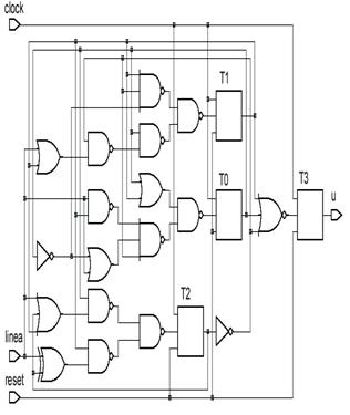
Figure 5.15. Circuit b02
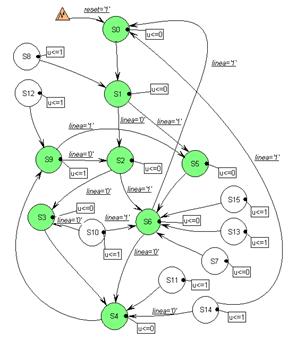
Figure 5.16. All state diagram of circuit b02
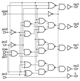
Figure 5.17. The combinational logic of circuit b02
Figure 5.18. Realisation of the model for circuit b02
The
realization of the proposed model for circuit b02 is presented in Figure 5.18,
where block b02c represents combinational logic of the
circuit, blocks N and P are
Table 5.5. The results of experiments with Forward State Search procedure on example circuit. S1 I tSCC
|
Itn. | |||||
|
P | |||||
|
R |
Table 5.6. The results of experiments with Forward State Search procedure on example circuit. S15 tSCC
|
Itn. | ||||||
|
P | ||||||
|
R |
Backward state search procedure
By analogy with
Theorem 3 The procedure BSS identifies all states from which a given initial state can be reached.
Proof: Suppose a circuit C has a state S from which an initial state can be reached, but this state is not in the collection N upon termination of the procedure BSS. This means that there exists a state S I N, which can be reached from S, and also exists a test vector that brings the state S to S. This test vector detects at least one fault of the combinational logic. However, it is a contradiction to the fact that procedure BSS did not detect any fault of combinational logic and did not return any test vector for the collection of states N.
Build the model of synchronous sequential circuit C as presented in Figure 5.12.
N := ; P := ;
Apply to the model test generation procedure for all single stuck-at faults of combinational logic. All the next state variables are assumed to be observable. All the primary inputs and present state variables are assumed to be controllable.
The present state variables of the test vectors identify some collection R of predecessor states, from which the states in the collection N are reachable.
If the collection of predecessor states R is empty, then collection N consists of states from which an initial state of the circuit C is reachable. Otherwise set N: = N R (N:= N after expansion of the first front), P: = P R and return to Step (3).
Figure 5.19. Procedure BSS to obtain states from which an initial state is reachable
The results of experiments with Backward State Search Procedure on example circuit are given in Tables 5.7 and 5.8. Note, we always get N:= (see Table 5.7) if procedure starts from a legal state.
Table 5.7. The results of experiments with Backward State Search procedure on example circuit. S1 I tSCC
|
Itn. | ||||||||
|
N | ||||||||
|
R |
Table 5.8. The results of experiments with Backward State Search procedure on example circuit. S15 tSCC
|
Itn. | ||
|
N | ||
|
R |
Identification of the exact collection of legal states
The reset or initialization sequence identifies at least one legal state of synchronizable circuits. However, no initialization sequence exists for non-synchronizable and partially synchronizable circuits. Recently Qadeer et.al. [14] have proposed an exact algorithm for computing tSCC. A tSCC is obtained by successively pruning the state space and performing forward and backward reachability computations from a state picked at random from the not reduced state space. If the state picked randomly belongs to a tSCC, then the forwardly reachable collection will be a tSCC and the picked state will belong to the backwardly reachable collection; otherwise, the whole backwardly reachable collection can be pruned away. In the worst case the forward or backward reachability computations may require the number of iterations exponential to the number of state variables. We suggest a new procedure for identification of the exact collection of tSCC for synchronizable, non-synchronizable and partially synchronizable circuits if no legal state is known in advance. The procedure we will describe initially gives an enlarged collection of legal states and converges rapidly to the exact solution.
Each state of the circuit has at least one successor. However, some states of the circuit dont have predecessors. A state is called a deadlock state if from this state no other state can be reached.
Definition 13 The circuit is a securely operating circuit (SO) if an operational behaviour of the circuit doesnt depend on the initial states after powering up.
A circuit is always securely operating circuit if all its states are legal. A circuit with deadlock states cant operate securely. A circuit can occur in the deadlock state after powering up.
Let
the procedure
Theorem 4 The tSCC= RF if RF RB.
Proof: The states of tSCC must satisfy the following conditions:
Any state in a collection is reachable from any other state in that collection.
No state in a collection can reach a state outside the collection.
A collection RF of states satisfies the second condition according to Theorem 2. Suppose a state S I RF cant be reached from other state S I RF. The initial state can be reached from S I RF, because S also belongs to RB. A state S can be reached from the initial state and, therefore, from the state S, what is a contradiction to the assumption that state S is not reachable from S.
Theorem 5 The states of the collection RB do not belong to tSCC if RF RB = .
Proof: Suppose a state S I RB belongs to tSCC. The states of the tSCC must satisfy the following conditions:
Any state in a collection is reachable from any other state in that collection.
No state in a collection can reach a state outside the collection.
The states of collection RF must belong to the same tSCC, because these states are reachable from the state S I RB. However, the state S is not reachable from the states of collection RF, because RF RB = . It is a contradiction to the condition 1 for tSCC, and the assumption that the state S I RB belongs to a tSCC is wrong. The initial state doesnt belong to the tSCC also, because the collection RB doesnt include RF.
Theorem 6 The collection RF includes all the states of tSCC for securely operating circuits.
Proof: Suppose
a state S belongs to a tSCC, but S RF. In this case
the state S of tSCC isnt reachable from any state of collection RF.
The procedure
Theorem 7 A securely operating circuit has at most one tSCC.
Proof: Suppose such a circuit has two terminal strongly connected components tSCC1 and tSCC2. A tSCC satisfies the condition that no state in a tSCC can reach a state outside the tSCC. The initial state after powering up can be a state of tSCC1, and from this state no state in tSCC2 can be reached. Therefore, the states of tSCC2 become not legal. It is a contradiction to the fact that the circuit is securely operating one and an operational behaviour doesnt depend on the initial states after powering up.
Theorems
4, 5 and 6 create a basis for procedure Identifying STates (
Build the model for state search of synchronous sequential circuit C as presented in Figure 5.12.
P := ; N := ;
Apply test generation procedure to the model for all single stuck-at faults of combinational logic. All the next state variables are assumed to be observable. All the primary inputs and present state variables are assumed to be controllable.
The present state variables of the test vectors identify some collection T necessary for detecting faults of the combinational logic. Select at random an initial state S from the collection T.
Identify
using procedure
If S
I RF,
then identify using procedure BSS (among the states of collection RF)
the collection RB of states from which initial state S is reachable.
Otherwise, select other initial state S, which was last included into
collection RF by procedure
If RF = RB, then tSCC:=RF.
Otherwise set RF: = RF RB, select other
initial state S, which was last included into collection RF by
procedure
Figure 5.20. Procedure
The procedure
The results of experiments
with Procedure
Table
5.9. The results of experiments with procedure
|
Itn. | ||
|
Initial state |
S=S4 (legal state) |
tSCC=RF |
|
RF | ||
|
RB |
Table
5.10. The results of experiments with procedure
|
Itn. | |||
|
Initial state |
S=S8 (illegal state) |
S=S3, S3I RF |
tSCC=RF |
|
RF | |||
|
RB |
Identification of undetectable faults
A model for identifying
legal states can be applied for identifying
undetectable faults. The procedure
Build the model of synchronous sequential circuit C as presented in Figure 5.12
P: = ; N: = ;
Apply to the model test generation procedure for all single stuck-at faults of combinational logic. All the next state variables are assumed to be observable. All the primary inputs and present state variables are assumed to be controllable
Test generation procedure identifies undetectable faults of combinational logic
Figure 5.21. Procedure
Lemma 1: The response Z (I, S) of the fault-free circuit to the input sequence I and the response Zf (I, Sf) of the faulty circuit are different for at least on one legal state, reached by input sequence I, if fault f is detectable by the sequence I.
Proof: Suppose responses are different on an illegal state only. In this case the responses depend on the initial circuit state. However, it is a contradiction to the statement of Lemma 1 that fault f is detectable and responses are different for every pair of initial states S and Sf.
Theorem 8 The
faults identified as undetectable by procedure
Proof:
Suppose that a fault f identified as undetectable by
procedure
The results of identifying undetectable faults depend
on the cardinality of the state collection considered. The state collection
used in the procedure
Identification of the legal and illegal states from all possible states
The methods of the groups M3 and M4 apply forward and backward state search from all possible input and output states. The state collection shrinks by each iteration starting from the collection of all possible input (output) states. The procedure terminates if each state of the collection has at least one other state as predecessor in the collection. An implementation (procedure FBS) of both methods is given in Figure 5.22.
Build the model for identifying legal states of synchronizable circuit C as presented in Figure 5.12.
P := ; N := ; F := ;
Apply test generation procedure to the model for all single stuck-at faults of combinational logic. All the next state variables are assumed to be observable. All the primary inputs and present state variables are assumed to be controllable.
The next state variables of the obtained test vectors identify some collection R of states reached from the states in the collection P.
If the collection of reachable states R is not empty, then set F: = F R, N :=NR and return to Step (3).
If F = P, then collection F consists of states reachable from all possible input and output states. Otherwise set P: = F; N: = F; and return to Step (3).
Figure 5.22. Procedure FBS to obtain a collection of states with at least one predecessor in the collection
The results of experiments with Procedure FBS on example circuit are given in Table 5.11.
Table 5.11. The results of experiments with procedure FBS on example circuit
|
Itn. | ||||
|
P |
|
| ||
|
N |
|
| ||
|
R | ||||
|
F |
F=P |
Algorithm FILL [4] eliminates self-loops of states by identifying illegal states from all possible states. The model for eliminating self-loops for unified framework is shown in Figure 5.23. Forbidding the same states on the input and output of combinational logic eliminates self-loops of states. This is achieved by requesting permanent value true on the output of the gate M2 (modulus 2).
Figure 5.23. A model for eliminating self-loops
Experimental results
The collection of reachable states identified on the iterative logic array model should be theoretically larger than the exact collection of tSCC. The goal of experiments is to compare the cardinality of the exact collection tSCC and of the collection of reachable states identified on the iterative logic array model and to establish what influence it has for identifying of undetectable faults
The
present and next state search space constraints of the model in Figure 5.12 are
implemented as
Note that modification of the circuit by routing a global reset signal to all FFs significantly changes the quantity of tSCC states. For example, the original circuit S344 has 1458 legal states, whereas the circuit with global reset signal has 2625 states. Therefore, the cardinality of legal states exact sets given in [4] is not correct for some circuits.
We
used as examples the ISCAS89 Benchmark circuits and b02 and b03 circuits from
The
columns under heading
Table 5.12
|
Circ. |
FBS |
FBS -loops |
|
|
|
#FF | ||||||
|
States |
Und |
States |
Und |
States |
Und |
States |
Und |
States |
Und |
|||
|
s298 | ||||||||||||
|
s344 | ||||||||||||
|
s349 | ||||||||||||
|
s386 | ||||||||||||
|
s510 | ||||||||||||
|
s641 | ||||||||||||
|
s713 | ||||||||||||
|
s820 | ||||||||||||
|
s832 | ||||||||||||
|
s1196 | ||||||||||||
|
s1238 | ||||||||||||
|
s1488 | ||||||||||||
|
s1494 | ||||||||||||
|
b02 | ||||||||||||
|
b03 |
>2500 |
1.92e-4 |
||||||||||
However, the sequential static learning approach [16] gives almost the same number of undetectable faults as that obtained using exact collection tSCC. It allows concluding that practical procedures based on the iterative logic array model with sequential static learning give a solution very close to the solution produced using the exact collection of tSCC for the circuits considered.
In a typical ASIC (Application specific integrated circuit) development process a gate circuit description is mostly generated automatically with the help of synthesis tools, and the developer works mainly with a high level circuits description. However most of the testing actions (testing structure insert, generation of test sequences, test completeness evaluation, etc.) are performed at the gate level. Therefore the conceptions of testability for the digital circuits are traditionally determinate and being used at the gate and lower levels. Most of the test generation methods and all the commercial testing systems use the gate circuits description and the stuck-at faults model for test generation.
An automatic generation of test sets for sequential circuits is a particularly complex process of computation. ATPG algorithms can generate test sets for complex circuits for many hours without obtaining any good results (the obtained test will test only a minor part of faults). We can name such factors that cause the complexity of this problem [17]:
Striving to simplify tasks of sequential ATPG various methods that improve the testability of sequential circuits are used; such methods are also called as DFT techniques. They are divided into three main groups: Ad-hoc, Scan and BIST [18].
The method presented in this section can be attributed to the class of Ad-hoc methods. The novelty of this method is that the structure it uses will be defined and this structure has to be applicable to various circuits. As well the advantages over the other DFT methods are sustained: a small amount of additional equipment, a possibility of at-speed testing, furthermore, there is an attempt of maintaining the other parameters as an additional amount of conclusions and the functionings degradation equivalent.
Extraction of the hard to detect fault
The basis of the hard to detect faults extraction method is in the iterative logic array model (IM) of the sequential circuit and in applying the combinational automatic test generator. Test sets generated according IM detect a fair amount of faults and can fully compete with sequential ATPG of industrial systems. However this method as another test generation methods encounter one of the ultimate problems of developing tests for synchronous sequential circuits; this problem is undetected faults of the obtained test. The set of these faults can be divided into two sets:
Definition 1 Undetectable fault this is such a fault when there is no test sequence that observes this fault response.
Definition 2 Hard-to-detect fault this is such a fault for which the test generator is incapable to find a test sequence because of the circuits complexity or limited systems resources; and there is no prove that such a test sequence doesnt exist.
In
the initial situation when using the iterative model for the sequential circuit
the obtained test does not detect all faults, the goal of the method is to
extract the set ![]() of hard to detect faults. This method is
divided into such stages:
of hard to detect faults. This method is
divided into such stages:
The set of input faults is
formed into which only the faults undetected by the test are included, i. e.
from the whole set ![]() of faults
of faults ![]() detected by the IM and ATPG are rejected.
detected by the IM and ATPG are rejected.
One copy of the IM with all
open feedbacks is used; undetectable faults ![]() detected by the test generator are rejected from the set of
input faults. If there are hard to detect faults we can select additional
equipment that helps to detect them in one copy;
detected by the test generator are rejected from the set of
input faults. If there are hard to detect faults we can select additional
equipment that helps to detect them in one copy;
The settings IM with all
open feedbacks is used; undetectable faults ![]() detected by the test generator are rejected from the set of
input faults;
detected by the test generator are rejected from the set of
input faults;
The available complete set
of legal states or the available partial set of
illegal states is used; faults ![]() undetected by the
obtained set are rejected from the set of input faults as undetectable;
undetected by the
obtained set are rejected from the set of input faults as undetectable;
Faults remaining in the set of input faults are hard to detect faults
The next stage is performed
only in such a case if the set of input faults is not empty. The results of the
functioning of this method can be illustrated graphically (see Figure 5.24)
showing the undetectable faults subsets ![]() ,
, ![]() ,
, ![]() extracted in each
stage. The set
extracted in each
stage. The set ![]() of hard to detect faults is extracted after having
subtracted the detected faults set
of hard to detect faults is extracted after having
subtracted the detected faults set ![]() and the undetectable
faults set
and the undetectable
faults set ![]() from the whole faults
set
from the whole faults
set ![]() .
.
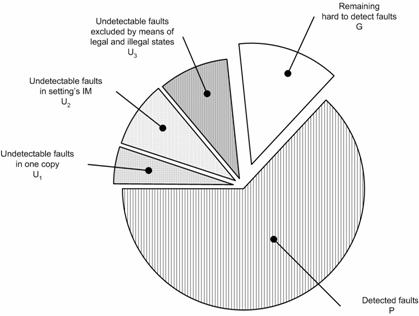
Figure 5.24. Distribution of U, G, and P sets
The search for legal states can be initiated in two ways. If
there is a possibility to set (there exists a setting sequence) the sequential
circuit to one or several known states so the search can be initiated from
these initial states. If the sequential circuit does not have a setting
sequence to at least one known state so the search can be initiated from any
state (from the full set of states). Whereas most sequential circuits under development
have set and/or reset functions for their initialization (setting to the
known state) after the switching-on and all the
The search for illegal states is a more common task than the search for legal states. This happens because selecting complete sets of legal or illegal states for huge sequential circuits (that have a large number of flip-flops) is a too complicated task. And from partial sets only a set of illegal states can be efficiently used it can be used for identifying undetectable faults. Currently in practice the search for illegal states is realized differently: the search is performed during the test generation, searching for pairs or triplets of illegal flip-flops values in the sequential circuit, searching for predecessors that have no states, the indirect search based on the IM and on reducing the expanded set of legal states, the search procedures based on IMs modifications and on the combinational ATPG [19, 20].
Having large sequential circuits the selection of complete sets of legal or illegal states can become troublesome to overcome. Then the task of identifying the state becomes more relevant. The state identifying procedure builds upon the so called search back. This search is performed in the opposite direction than is used in procedures of the search for legal or illegal states then it is searched for such states to which the circuit can move from the present states. Here it is searched for states from which the circuit could move to the present states.
Increasing the controllability
The essence of the method of increasing the controllability is to select qualitatively an additional logic that increases the controllability of the sequential circuit and guarantees the testing of hard to detect faults. This method consists of two stages: the finding of proper flip-flops for increasing the circuits controllability and the realization of observing or setting these flip-flops by selecting additional equipment.
Having excluded the set of hard to detect faults there raises a problem about the way to test them. This problem has to be solved using one of DFT methods. The method chosen in this section can be assigned to the class of Ad-hoc methods. Its main advantage over the other methods is a small amount of additional equipment that increases the controllability of the sequential circuit. As well we will seek for generalizing and proposing the structure for this DFT method and this is not used applying the other Ad-hoc methods. It should be mentioned as well that this method consists of two stages. The first stage is purposed for finding the proper flip-flops in order to increase the controllability of the sequential circuit. Two sets of flip-flops that have to be observed and set will be obtained in this stage. In the second stage additional equipment that guarantees observing and setting of these sets of flip-flops will be selected.
The initial situation is
such we have a sequential circuit and a set ![]() of hard to detect
faults. The aim is to set
flip-flops which having under control
faults of the set
of hard to detect
faults. The aim is to set
flip-flops which having under control
faults of the set ![]() would become
detectable; i. e. the ATPG would find test sequences for
these faults. In such a way 100% test coverage will be reached.
would become
detectable; i. e. the ATPG would find test sequences for
these faults. In such a way 100% test coverage will be reached.
![]()
(1)
Flip-flops for observing and setting will be collected separately. Two sets will be collected: a set S of flip-flops for observing and a set N of flip-flops for setting. On the grounds of the practical experiments the set G can be divided into four subsets. They are classified according to their testing requirements, i.e. they can be tested:
a) observing some flip-flops only,
b) setting some flip-flops only,
c) observing or setting some flip-flops
d) observing and setting some flip-flops
Additional equipment will be
designed for observing and setting separately too. In the obedience to the
theoretical consumptions on average additional equipment purposed for observing
one flip-flop additionally will be smaller than for setting one. Consequently
on purpose to test the subset c) of faults increasing the observability the
collection of the sets ![]() and
and ![]() will be started from
the set S. Without the IM there will be used logic SL which helps to locate the
flip-flops observed during the test
generation. Considering these statements the procedure for collecting sets
will be started from
the set S. Without the IM there will be used logic SL which helps to locate the
flip-flops observed during the test
generation. Considering these statements the procedure for collecting sets ![]() ,
, ![]() is prepared and
presented.
is prepared and
presented.
In order to perform
practical experiments this procedure is simplified. Selecting the set ![]() of flip-flops for observing and the set
of flip-flops for observing and the set ![]() of flip-flops for
setting, for the faults subsets a),c) and b),d), respectively, no iterations
were used, i. e. such flip-flops were included to these sets which were chosen
by the ATPG having realized an automatic
selection.
of flip-flops for
setting, for the faults subsets a),c) and b),d), respectively, no iterations
were used, i. e. such flip-flops were included to these sets which were chosen
by the ATPG having realized an automatic
selection.
Selecting the sets ![]() ,
, ![]() according to the
unsimplified procedure the ATPG should be run about
according to the
unsimplified procedure the ATPG should be run about ![]() times. According to
the simplified procedure the ATPG will be run only three times. However the
optimality of selecting the sets
times. According to
the simplified procedure the ATPG will be run only three times. However the
optimality of selecting the sets ![]() and
and ![]() will be lost. Two ways
are suggested for observing the set of flip-flops
will be lost. Two ways
are suggested for observing the set of flip-flops
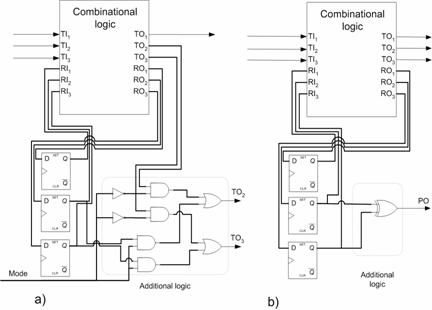
Figure 5.25. Flip-flops observation using additional logic
Using the first way (![]() ).
).
The point of setting flip-flops is to set for the flip-flops such values which would enable to test the rest hard-to-detect faults at the required time frame. Two ways of implementing this requirement are suggested:
ATN1 to set flip-flops using available (original) inputs (Figure 5.26(a));
ATN2 to use additional equipment that minimizes the number of original inputs, used for setting the flip-flops (Figure 5.26(b)).
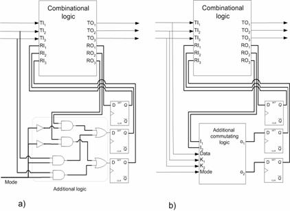
Figure 5.26. Setting Flip-flops using additional logic
The first way (ATN1) is a modification of the parallel partial scan when a value shifting into the required flip-flop is used only. Flip-flops are set to the required states through the original inputs using an additional logic and an extra control input. The test mode enabled through the control input emerges. This additional logic allows a parallel setting of the flip-flops in the test mode to the required states through the original inputs. The amount of the additional logic can be calculated using the same formulas that were used to calculate the amount of the additional logic for observing the flip-flops using the first way. Just in this case the number of the circuits inputs must be taken instead of the number of the circuits outputs. This way is purposeful to use only in such cases when the number of flip-flops that must be set is lower than the number of the original outputs or given a specific task when it is better to use more extra inputs than more additional logic.
The point of the second way (ATN2) is setting the required flip-flops with the help of an additional logic and an extra control input using the original inputs for transmitting the value and the number of the required flip-flop. If the circuit is working in the normal mode (the value of the control signal is 0) the commutating logic is working like simple wires, i. e. the values of the inputs are sent directly to the outputs. If the value of the control signal is 1 the circuit switches to the test mode. The commutating logic through the original inputs gets a code of the required flip-flop. According to this code the proper trigger is selected and the given value is inscribed in it. The number of the additional logics elements shall be calculated only after having performed a practical experiment.
Experimental results
The
experiments were performed with the
Table 5.13. Experimental results using IM
|
Circuit |
Amount of copiesn |
Faults |
Test coverage, %. |
Test generations CPU time, s |
||
|
All, T |
Untested |
Tested, P |
||||
|
B01 | ||||||
|
B02 |
0,45 |
|||||
|
B03 |
16,70 |
|||||
|
B04 |
70,13 |
|||||
|
B05 |
1296,50 |
|||||
|
B06 |
1,20 |
|||||
|
B07 |
1791,79 |
|||||
|
B08 |
250,24 |
|||||
|
B09 |
384,07 |
|||||
|
B10 |
379,06 |
|||||
Having performed all the stages of the method of excluding hard to detect faults we can generalize the results of the experiment (Figure 5.27). The least number of undetectable faults were set in the first stage and the largest number during the third stage. Even more undetectable faults would be set in the third stage if complete sets of legal states or larger sets of illegal states were used. Also it was influenced by not applying the third stage for the circuits B04, B05 and B08. This was not done as complete sets of legal states or partial sets of illegal states were not collected. The number of undetectable rejected faults and the rest hard to detect faults are presented in Table 5.14. We see that, e. g., for the circuit B03 a major part of undetectable faults were rejected during the third stage and there left less than 1% of hard to detect faults. Amounts of undetectable faults of our method are compared with amounts of sequential ATPG (TetraMAX). An experimental results show that our method is always superior.
Figure 5.27. Average of distribution of faults
Table Distribution of faults in benchmarks
|
Circuit |
All, T |
Detected, P |
Undetectable, U |
Hard to detect, P |
Undetectable by sequential ATPG (TetraMAX) |
||||
|
Amount |
Amount |
Amount |
Amount | ||||||
|
B02 | |||||||||
|
B03 | |||||||||
|
B04 | |||||||||
|
B05 | |||||||||
|
B06 | |||||||||
|
B07 | |||||||||
|
B08 | |||||||||
|
B09 | |||||||||
|
B10 | |||||||||
Having accomplished all stages of the method of excluding the set of hard to detect faults and having used the simplified procedure of finding flip-flops under setting and observing the results are shown in Table 5.15. S N will be used to evaluate additional equipment calculated according to the partial scan method. S N is compared to amount of scan FFs given by SSCM (State spatial correlation matrix) for circuits B07 and B08. Amount of scan FFs by SSCM is less than S N in case of circuit B07, but in both cases fault coverage is lower using SSCM.
Table Observable and settable flip-flops
|
Circuit |
Observable FF, S |
Settable FF, N |
S N / All FFs |
Scan FFs by SSCM / All FFs |
|
|
1 |
0 |
1 / 4 |
- |
|
B03 |
4 |
0 |
4 / 30 |
- |
|
B04 |
34 |
2 |
35 / 66 |
- |
|
B05* |
19 |
28 |
32 / 34* |
- |
|
B07** |
39 |
34 | ||
|
B08 |
2 |
4 | ||
|
B09 |
8 |
8 | ||
|
B10 |
6 |
4 |
- test coverage 92,56 %.
- test coverage 97,68 %.
- test coverage 96,45 %.
- test coverage 98,98 %.
Applying
such a simplified procedure the flip-flops under observation and setting were collected
in the course of three stages. Further on the evaluations of the proposed
additional equipment used to observe the flip-flops of the set S (Table 5.16)
and to set the flip-flops of the set N (Table 5.17) are presented; these
evaluations are shown in the
Table Amount of additional logic for observing flip-flops
|
Circuit |
|
|
||||||
|
V |
I |
L |
Area |
V |
I |
L |
Area |
|
|
B02 |
4 |
1 |
6 |
7 |
0 |
1 |
1 |
0 |
|
B03 |
16 |
1 |
24 |
25 |
3 |
1 |
7 |
6 |
|
B04 |
136 |
27 |
204 |
205 |
33 |
1 |
67 |
63 |
|
B05 |
76 |
1 |
114 |
115 |
18 |
1 |
37 |
33 |
|
B07 |
156 |
32 |
234 |
235 |
38 |
1 |
77 |
71 |
|
B08 |
8 |
1 |
12 |
13 |
1 |
1 |
3 |
4 |
|
B09 |
32 |
8 |
48 |
49 |
7 |
1 |
15 |
13 |
|
B10 |
24 |
1 |
36 |
37 |
5 |
1 |
11 |
11 |
Table Amount of additional logic for setting flip-flops
|
Circuit |
ATN1 |
ATN2 |
||||||
|
V |
I |
L |
Area |
V |
I |
L |
Area |
|
|
B02 |
0 |
0 |
0 |
0 |
0 |
0 |
0 |
0 |
|
B03 |
0 |
0 |
0 |
0 |
0 |
0 |
0 |
0 |
|
B04 |
8 |
1 |
12 |
13 |
6 |
1 |
11 |
10 |
|
B05 |
112 |
27 |
168 |
169 |
153 |
5 |
170 |
269 |
|
B07 |
136 |
33 |
204 |
205 |
173 |
6 |
215 |
342 |
|
B08 |
16 |
1 |
24 |
25 |
16 |
1 |
24 |
24 |
|
B09 |
32 |
7 |
48 |
49 |
29 |
3 |
42 |
45 |
|
B10 |
16 |
1 |
24 |
25 |
16 |
1 |
24 |
24 |
We see from the tables that in all cases we need less additional equipment for observing when the second way is used. We need less logic for setting while using the first way only for the complex circuits B05, B07 yet the second way requires less extra conclusions. Therefore having chosen the way that fits better for observing and setting we can realize this way in the sequential circuit. We compare the amount of the proposed additional equipment to the amounts of additional equipment in case of the Full-scan and the Partial-scan (Table 5.18). In case of the Scan technology the amount of additional equipment for one AT is 4 gates that cover 7 units of the area.
Table Comparing additional logic amount to full and partial scan
|
Circuit |
Logic of full scan, %. |
Logic of partial scan, %. |
Proposed logic (observation way setting way) |
|||
|
|
|
|
|
|||
|
B02 |
35,00 |
8,75 |
8,75 |
8,75 |
0,00 |
0,00 |
|
B03 |
38,89 |
5,19 |
4,63 |
4,63 |
1,11 |
1,11 |
|
B04 |
31,09 |
16,49 |
14,67 |
14,47 |
5,11 |
4,91 |
|
B05 |
15,17 |
14,28 |
18,10 |
24,47 |
12,87 |
19,25 |
|
B07 |
28,70 |
27,57 |
35,37 |
46,38 |
22,19 |
33,20 |
|
B08 |
29,76 |
5,67 |
7,69 |
7,49 |
5,87 |
5,67 |
|
B09 |
38,58 |
19,29 |
19,29 |
18,50 |
12,20 |
11,42 |
|
B10 |
24,64 |
14,49 |
12,84 |
12,63 |
7,45 |
7,25 |
We see from the results that only in cases of the circuits B05 and B07 the experiment did not prove. That could be caused by the simplification of collecting the sets S, N that reduced the optimality of the solution. Due to this simplification the task of collecting the sets S, N became too complex for the ATPG with available resources and 100% test coverage for these circuits was not reached.
In summary we can assert that the procedure of selecting the sets of flip-flops under observing and setting and the proposed ways to realize the observation and setting of flip-flops has proven. The advantages of these ways as compared with the full and partial scan method are fewer amounts of additional equipment, a shorter test and at-speed testing.
Conclusions
Circuit description language VHDL gives an opportunity easy to generate logic array model of sequential circuit and practically to use combinational ATPG for test generation of sequential circuits. The iterative logic array model by introducing faults in one or in all copies of the circuit allows in mosr cases to get higher fault coverage as compared to the famous test generation tool HITEC. At that time the iterative logic array model creates new possibilities for effective test generation, because enables easy to manage the test generation process.
We
have presented a unified framework for identification legal states and
undetectable faults in synchronous sequential circuits. Most known methods
for identification legal states and undetectable faults are interpretable
within this framework. The framework uses the combinational logic of
sequential circuit and
The direct preparation and configuration of the iterative models of the sequential circuit and use of it with the combinational ATPG allows obtaining higher results than the sequential ATPG in solving such tasks like extraction of undetectable faults and test generation.
Theoretical and simplified practical procedures of finding flip-flops sets under observation and setting were proposed in this work. The task of the procedures is to find the smallest values of these flip-flops sets that enables to test hard to detect faults. In experiment the simplified practical procedure was used. Its result could be worse than theoretical because of test generators ability to chose smaller amount of test patterns instead of smaller amount of flip-flops under observation and setting. The ways for the realization of observing and setting flip-flops were proposed as well. The particularity of their usage and the expenditure of additional equipment were outlined.
References
|
Politica de confidentialitate | Termeni si conditii de utilizare |

Vizualizari: 3262
Importanta: ![]()
Termeni si conditii de utilizare | Contact
© SCRIGROUP 2024 . All rights reserved