| CATEGORII DOCUMENTE |
| Bulgara | Ceha slovaca | Croata | Engleza | Estona | Finlandeza | Franceza |
| Germana | Italiana | Letona | Lituaniana | Maghiara | Olandeza | Poloneza |
| Sarba | Slovena | Spaniola | Suedeza | Turca | Ucraineana |
A 3000 Ns SugarSodium Nitrate motor development for space education
Stancato, F.
Universidade do Norte do Paran
Catalani Racca, J. G., Castaldo, F., Carbonari, G., Souza, L.A., Ballarotti, M.G.
Universidade Estadual de Londrina
Londrina, Paran State - Brazil
ABSTRACT
A solid propellant motor was developed for use in two rocketry groups in Brazil: the Grupo de Foguetes Experimentais GFE and the Ncleo de Atividades Aeroespaciais NATA. The motor would fulfill the following characteristics:
Reliability;
Safety;
No hazard propellant manipulations;
Low cost firing;
Capability to send a 12 Kg loaded rocket to a 2000 meters altitude;
Reusability;
No ambient aggressiveness;
Copyright 2000 by Fernando Stancato. Published by the American Institute of Aeronautics and Astronautics, Inc., with permission. Released to IAF/IAA/AIAA to publish in all forms.
A 3000 Ns motor was built using sugar sodium nitrate unrestricted burning unit, single hollow charge.
It is described the project development and qualification tests. A static test stand with digital acquisition system was developed and used.
The thrust curve was measured and a regressive burning characteristic was found, being ideal for short launch towers and low structural loads.
Although not extensively used in rocketry field the sugar - sodium nitrate propellant proved to be an excellent alternative for medium experimental rockets, especially for safe and low cost firing characteristics
In 1988 it was formed an experimental rocket group called Grupo de Foguetes Experimentais in order to make university and high school students apply their knowledge in Mathematics, Physics and Chemistry in the design, construction, tests and launch of an experimental rocket. In 1995 it was developed the first successful 250 Ns solid propellant called M1. Soon an 750 Ns motor was developed with composite tube. These motors were used in more than 15 launches from 1995 to 2000. The rockets used in this launches had 63 mm in diameter, 1,5 to 1,8 meters in length and carried only a recovery system and an accelerometer.
The first project was an experimental rocket that would carry diverse instruments. The general characteristics was a 12 Kg loaded rocket with an apogee about 2000 meters. This led to an 3000 Ns motor. This motor would serve both NATA and GFE group.
As the objectives of both groups is to give a hands-on experience to the students on space area the motor would fulfill some requirements:
No hazard propellant manipulations. As the propellant was going to be manufactured by the students a safe and non toxic materials was a necessity as we do not have specialized laboratory installations;
Reliable. The manufacturing process must have not much restrictive properties margins as it was not going to be made by specialized professionals;
Low cost. It would permit a great number of tests and launches without excessive propellant costs.
Reusable. The motor hardware must permit a great number of firing.
No ambient aggression. The burning gasses would have no toxic or ambient aggression characteristics.
It was decided for a solid propellant motor for its low cost hardware and rapid development. It was studied some modern composite propellants but the price and availability of some components made it unaffordable. It was decided to use the sugar-sodium nitrate for its low price, easy access reliability and safe manipulation. Development time would be shortened as the GFE had used it extensively in the M1 and M2 motors.
Chamber Pressure, Pc
It is designed the initial chamber pressure as it was expected the thrust curve to be regressive as it was the same grain motor geometry predecessor motors M1 and M2. The initial chamber pressure was choused as 20 Kgf/cm2.
Grain
It was decided to use an unrestricted single hollow charge. Measurements of the specific impulse of this propellant in the M1 motor led to the value of 78 seconds.
The mass of the propellant, mp can be calculated by:
mp= It/(Is .g) (1)
where:
Is = Specific impulse (s)
g = Gravitational constant (m/s2)
Using It = 3200 N.s and Is = 78 s we get from equation (1) a total mass of 4.180 Kg of propellant. Using propellant density value of 1.73 g/cm3 a grain was calculated:
External Diameter: 79 mm
Internal Diameter: 10 mm
Length: 51 mm
Burning Area: 1,402.25 cm2
Using a correlation from STANCATO, 19972:
ro = 0,0728 . Pc 0,5098 (2)
Pc = Chamber Pressure (Kgf/cm2)
Using a chamber pressure of 20 Kgf/cm2, from equation (2) we have a burning rate of 0.3353 cm/s.
Eroding burning rate
It was found with tests of small motors (STANCATO, 1997)2 with unrestricted grain that a pronounced erosive burn occurs, specially at the beginning of the burning as the M1 and M2 motors had a initial small port area. It was found that an erosion coefficient (e) must be used for correct burning rate estimation:
e = r/ro (3)
where:
r = eroding burning rate
ro = linear burning rate without gas flow parallel to its surface.
In many static and dynamic tests it was found an value of 1.4 for the erosion coefficient. Using equation (3) we have an r value of 0.4694 cm/s.
Gas mass flow, mg
The gas mass flow that passes through the nozzle is
mg = X . r.r. Ab (4)
where:
Mass fraction of gasses in the exhaust, X = 0.7894 (STANCATO, 1997)2
Eroding burning rate, r = 0.4694 cm/s
Propellant specific mass, r = 1.73 g/cm3
Burning area, Ab = 1,402.25 cm2
From equation (4) and the above values, the mg= 0.899 Kg/s.
Throat Area, At
The throat area can be calculated by:
At = mg .X (g. Tc R/M) (5)
G . Pc
where:
g = ratio of specific heats,
Tc = combustion temperature
M = molecular weight of gas products
G g g g g
|
Press. |
Tc |
g |
X |
M |
G |
Cf |
|
(atm) |
(K) | |||||
|
| ||||||
Obs.: Cf = Thrust Coefficient
Table 1: Thermodynamic exhaust gases properties for different pressures.
Evaluating the gasses properties at
20 Kgf/cm2 we have an throat area of 5 cm2 or a throat
diameter of 25.4 mm.
Motor designing considerations
The motor wall thickness was calculated using simplified criteria of Strength of Materials for cylindrical tanks submitted to internal pressure, within the elastic limit.
Discontinuity stresses
additional stresses in edge junctions due to deformations of cylinder radius
and of closing cover were unconsidered in calculation. Longitudinal stresses
are not dependent on edges shape and were half of circumferential stresses.
Therefore, circumferential stresses ![]() are the main and it
values3:
are the main and it
values3:
 (6)
(6)
where:
p = chamber internal pressure;
R = external radius of motor cylinder;
e = thickness of wall;
Yield strength of steel fyk= 350 MPa;
Cylinder radius R = 48 mm;
safety factor adopted s = 7;
from equation (6):
![]()
![]()
![]()
![]()
![]()
Fig. 1. Schematic motor drawing
Propellant manufacturing
The following are the steps for manufacturing the propellant which will be used for testing and launching:
pounding the sodium nitrate
mixing and to drying the mixture of sodium nitrate and with sugar
Melting and molding the caramel
Pounding the sodium nitrate
The proportion used in the compound was 60% of sodium nitrate (NaNO3 combustible) and 40% of sacarose (oxidant)4. From 5 Kg of material used, there were 3 Kg of Sodium Nitrate and 2 Kg of refined sugar. The nitrate was pounded using a blender. The powder portion was put inside a pan. The grains that still remained together were pounded in the moar with the pestle. The powder of sodium nitrate retains humidity very easy and part of it remained sticked in the blender cup. To remove these it was used the long glass rod.
Mixing and drying the sodium nitrate with sugar
Procedures: it was used a digital balance to check the compound ingredients mass (3kg of sodium nitrate and 2 kg of refined sugar). Both of them were put into a pan for mixing. It was used a mechanic mixer to have a better homogenization of the combustible and the oxidant. The humid mass of the sodium nitrate and sugar was 5012 g.
The mixture was taken into a stove where it stayed for approximately 2 hours under a temperature of 800. Then it was put again in the mechanic mixer, and right after that the mixture were passed through a 16 sieve. The portion retained in the sieve was pounded with the flat head pestle.
Melting and molding the caramel
Procedures: initially it was prepared the steel mould in which was inserted the melted compound.
The mould has an internal haste, which was revolved with aluminum foil, to make easier to get it out.
One layer of transparences was put into the cylindrical mould.
Once the mould is ready it was begun the heating of the oil in the recipients. The compound (5 kg) was divided in two pans, which were put into the recipients with heated oil. It is necessary to keep mixing the material with the wooden spoons during the heating process to avoid scorching the compound .
Once the mixture become a caramel (when all the mixture melts), it was put into the mould. After that the mould was involved with common plastic and aluminum foil to insulate it and to avoid the absorption of humidity during the solidification process.
To obtain an estimate of the maximum thrust, a simple, highly portable and protected bench was constructed in steel with 4 mm thickness. The axial and vertical motor movement was allowed to avoid secondary forces interference in the test.
A load cell used for applied forces until 20,000N was installed in the bench and connected with an electronic Acquisition Signal System.
Within of laboratory room specially designed for this test, there were a TV monitor, the acquisition signal system and the motor ignition system control.
Fig. 3. Laboratory data acquisition system and test control
A Signal acquisition system based on the system ADS2000 is shown in fig.4 . In such scheme the motor applies force down over a load cell as the propellant burns. The exerted force over the load cell strain the gages and a small voltage signal proportional to the strength is generated by the load cell. The amplitude of this signal varies in mV range. A next signal conditioner amplifies the generated signal to a suitable amplitude before applying it to the A/D interface. Another signal adjustments are also carried out by the Signal Conditioner as filtering and galvanic isolation. In such arrangement only one of the AI2160 channels is used.
Fig. 4. Signal Acquisition System

The A/D interface converts the well-fitted input
analog signal into binary format that
can be recognized by a computer-based system. The 12-bits conversion process based on successive-approach
scheme fits all the requirements concerned to conversion time allowing
time-variable signals as fast as by tens of KHz being sampled. In such essay the sampling rate
was 5000 points a second, a good agreement between results accuracy and file
storage size on a computer in events up to
some dozens lasting. Such sampling rates
prevents also the aliasing effect. After signal conversion the electrical
equivalent input acquired from the load cell becomes a digital word and can be
sent to the computer through parallel interface. The next step the software
reads the measured points and shows them into a adequate physical amount on a
display. In this essay, the related physical amount were force given in
Kilogram-force and elapsed time given in seconds. The software also features
handling and showing data capability allowing the user to get information
concerning the subject under investigation.
The figure 5 shows a kind of connecting the load cell to the AI2160 input. Note the Whetstone configuration used. As the range of applied strength gets up to one thousand of Kilogram-Force, the electrical equivalent output varies into some dozens of milivolts range when 10 V supply is used. An additional signal amplification of 600 can be set by the user provided in the AI2160 control adjusts to the present experiment.

As result of such arrangement an output electrical signal ranging between 0 and 5 V is therefore sent to the A/D Interface. After conversion and sending data through parallel interface to the computer the software sets the scale factor so the physical amounts can be read out directly on graphic displays as shown in figure 6. To do so a calibration process should be carried out before the experiment takes place.
Fig. 6. Visualizing a physical amount time-varying
waveform
Calibration Process: After properly operation of the acquisition system a calibration process can be launched prior the beginning of the experiment. The goal of this process relies on setting both an upper and lower physical amount in accordance with the signal range sent to the A/D converter so an adequate display of the physical amount (e.g. Force) can be read out as shown in figure 7.

However this signal range can be settled by the user by adjusting Signal Conditioner controls the user should know about the relationship between the output voltage range picked up from the transducer (e.g. load cell) and the physical amount applied to it. The calibration process demands a kind of adjustment called 'Linear Regression' where some measured points are entered and another ones are calculated by interpolation. A best correlation between the actual values of the physical amounts and the measured ones takes place in such scheme. This process also prevents from inaccuracies of the whole system. To perform the calibration process the user just apply some known values of the physical amount (e.g. standard weights) to the transducer and relates them to the computer in a look-up table that will be used to calculate the correlation afterwards. The figure 8 shows a window launched to execute this operation. Once completed the system is ready to proper operation.
Fig. 8. Window for calibration
Total impulse (It) is defined as the integral of the thrust (F) over the operating duration (t) of the motor:
![]() (7)
(7)
The obtained curve from static testing indicated a thrust maximum of 1,540 N and a total impulse of 2,874 Ns.
Fig. 9. Motor thrust curve
MOTOR thrust from flight analysis
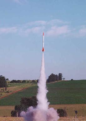
The idea of constructing the engine thrust curve (of motor M3) from data of flight appeared with the launch of Cabral rocket. 2.6 m long, weighting 14.185 Kg, 10 cm of diameter, 4.135 Kg of propellant mass, Cabral got an apogee of 1,900 m. Cabral rocket flew in April 24 of 2000. There was an onboard system to acquire acceleration, velocity and altitude data of all flight.
Fig. 10. Cabrals lift-off
The thrust curve of the motor is obtained from these data. Using Newtons first law,
![]() (8)
(8)
where:
F = motor thrust (N)
m = mass of rocket (Kg)
a = acceleration (m/s2)
FD = drag force (N)
and
![]() (9)
(9)
where5:
CD = drag coefficient;
r = air density (Kg/m3);
A = sectional area (m2);
v = velocity (m/s);
and
![]() (10)
(10)
where5:
h = altitude (m);
the unique unknown variable will be the mass of the rocket (m) that changes during the flight.
As the gas mass flow is proportional to acceleration2, the consumed propellant mass can be calculated by:
 (11)
(11)
where:
![]() = consumed mass until time t (Kg)
= consumed mass until time t (Kg)
![]() = sum of accelerations values from t = 0 until time t
= sum of accelerations values from t = 0 until time t
![]() = sum of sum of accelerations values from t = 0 until burnout
= sum of sum of accelerations values from t = 0 until burnout
![]() = total propellant mass (Kg)
= total propellant mass (Kg)
The curve below resulted in 3220 Ns of total impulse.
Fig. 11. Motor thrust curve of M3 from Cabrals flight
Conclusion
Although the motor had a shuffing effect in the static test the total impulse on both static and flight was about the expected 3,000 Ns.
A regressive thrust curve was obtained on both test being a good characteristic for experimental rocket launch where short launch rail can be used.
Although not extensively used in rocketry the sugar-sodium nitrate propellant proved to be an excellent alternative for medium experimental rockets, specially for safe and low cost firing characteristics.
References
1. Sutton, George P. Rocket Propulsion Elements - An Introduction to the Engineering of Rockets. New York, John Wiley & Sons, INC., 1965, 466 p.
2. Stancato, Fernando and Miraglia, Jos Internal Ballistic Principles a Methodology and an Experimental Didactic Experimentation. International Mobility Technology Conference and Exhibit, Sao Paulo, Brasil, October 27-29, 1997. SAE paper n. 973087P.
3. Timoshenko, Stephen P., Strength of Materials, D. Van Nostrand Company, Inc., 1930
4. Vyverman, Tony The potassiumnitrate - sugar propellant. A Workinggroup Propulsion publication, 1978.
5. Roberson, John A., Crowe, Clayton T., Engineering Fluid Mechanics, Houghton Mifflin Company, 1975.
|
Politica de confidentialitate | Termeni si conditii de utilizare |

Vizualizari: 1570
Importanta: ![]()
Termeni si conditii de utilizare | Contact
© SCRIGROUP 2025 . All rights reserved