| CATEGORII DOCUMENTE |
| Asp | Autocad | C | Dot net | Excel | Fox pro | Html | Java |
| Linux | Mathcad | Photoshop | Php | Sql | Visual studio | Windows | Xml |
![]() LAN Design Guidelines for the Implementation of MN3300
Platforms
LAN Design Guidelines for the Implementation of MN3300
Platforms
Network Guidelines for Voice over IP Installations
Executive Summary
Summary of Guidelines
Guidelines and Explanations
Introduction
Terminology Explanations
Delay
Echo
Jitter
Packet Loss
Available Bandwidth
Packet Priority Mechanisms
WAN Connections
Transcoding and Compression
Hubs Versus Switched
LAN Architecture
Maintaining Voice Quality of Service
Network Measurement Criteria
Bandwidth Requirements
CODEC selection
Available Bandwidth
LAN
WAN
Serialisation Delay
Network Priority
LAN Layer 2 Priority
WAN Layer 3 Priority
Network Topology with Priority
Use of Subnets
Maintaining Availability of Connections
System Capabilities
Traffic
WAN traffic worked example
IP Trunking limits
IP Trunk Limit working example
Getting Started
Start-up sequence for phones:
Start-up Sequence for the Controller
DHCP Options
DHCP Lease Time
The following information is to be used in determining the suitability and requirements for a Voice over IP installation. The MITEL 3300 Integrated Communications Platform (ICP) will be used to illustrate some of these areas.
The MITEL 3300 ICP includes a number of functions such as gateway between IP and TDM, call control, as well as TDM and PSTN connections. Each part may be described separately or as a part of the overall unit, sometimes also referred to as the controller.
The contents of this document should be used in assessing the capabilities of a particular network with respect to maintaining voice quality and usability of the IP-Phones and associated controllers.
Networks by definition do not always follow specific architectures, so whilst every effort is made to give accurate information, requirements may differ between different installations. As a result the information enclosed is typically generic in nature. Specific information on how the configure the MITEL 3300 ICP and network equipment should be referred back to manuals and relevant training on those devices.
The main requirement in assessing and configuring the network is maintaining the voice quality and functionality to the user. This may require that certain changes take place within an existing network, or that equipment with certain capabilities is installed.
The main issues that affect the voice quality within a network are:
Network Delay
Network Jitter
Network Packet Loss
Care has been taken in the design of the IP-Phones and controllers to cater for delay through the inclusion of echo cancellation devices. The jitter and a certain degree of packet loss are also taken care of by the inclusion of jitter buffers and the mechanism to control these.
In implementing a network to handle Voice over IP the following areas need to be considered. These are recommendations, and there will always be exceptions, but these should be considered:
QoS (Quality of Service) Quality of service is that provided to the user, not network equipment settings. However, certain network equipment configurations can greatly assist in ensuring adequate QoS to a user. These include:
IEEE802.1p/Q:
This may also be known as VLAN Tagging, priority or
DiffServe: This is a fixed field in the Layer3 information that is also used to define different service categories, through TOS, priority and Precedence. DiffServe and Type of Service are similar, with the older Type of Service values being backward compatible into DiffServe.
Switched Networks: Use switched networks, which then allow full bandwidth capability to all end points. Networks with Hubs include shared bandwidth and no priority mechanisms are available, see above.
Network Topology: The networks should be designed in a hierarchical manner where bandwidth between devices is controlled and understood. Simply linking switches in a long chain will work for data, but this also introduces bottlenecks between devices that are unnecessary, as well as introduction of jitter.
Network Pre-Installation and post-installation analysis: The network should be investigated before installation to determine suitability for Voice over IP. The following sections of the document will provide guidelines of areas to investigate. Once an installation is completed, it should also be tested to ensure that the guideline limits are not being exceeded.
NAT and Firewall: Although there are emerging standards to allow Voice over IP through firewalls and NAT devices, these are still in early development. Typically to allow voice through a firewall a number of ports need to be opened up, since one controller may use a range of ports that are dynamically assigned. Opening up all possible ports negates the usefulness of the firewall. NAT needs to change addresses, but may have difficulty in mapping a single controller device to multiple Internet addresses, or translating IP addresses that are buried in control messages. Generally these issues are overcome through the use of VPNs.
VPN: Virtual Private Networks are simply a pipe or tunnel across an ISP network which allows a remote device to react as though it was still connected to the enterprise network. Beware that the VPN may be across an unknown network. It may be required to get certain Service Level Agreements (SLA) to ensure timely delivery of data. Where encryption is used additional delay may also be added to the data.
In brief, the guidelines are exactly that: guidelines. Because LANs are so diverse and equipment changes so quickly the following recommendations are listed below to provide the best operating conditions.
Use networks with VLANs (IEEE802.1p/Q) with dual port phones
The network should be fully switched. Hubs do not support priority queuing.
The ports must allow for the interface speed to be configured either manually or automatically.
Routers or Layer3 switches must be available to connect between VLANs
Spanning Tree should be disabled at the controller connection (pre release4.0).
Only one LAN connection should be made from the ICP controller to the network
The controller should be located behind a network Layer2 switch
Ensure that the PPS rate of the routers and switches is adequate for the amount of voice traffic expected
Wherever possible, provide the most bandwidth. Use Full duplex in preference to Half duplex.
If the network consists of multivendor units, do they all inter-work correctly?
Use MTU on routers especially for slower speed links (anything less than T1 rates)
Ensure that end-to-end delay, jitter and packet loss are within acceptable bounds
Ensure that there is sufficient bandwidth on a WAN link for the amount of expected traffic. Don't overload, otherwise everyone suffers
Provide a realistic blocking number for IP Trunking restriction, i.e. consider bandwidth
Don't share the voice VLAN with data devices
Don't put servers or printers behind a dual port phone, provide a dedicated port for these devices.
Ensure Routers support DHCP forwarding, or provide multiple DHCP servers and copy phone specific information between DHCP servers to ensure phones start up correctly.
Ensure Routers support 'ICMP Redirect'. This reduces bandwidth requirements when the 'default gateway' device is not the correct one to direct traffic to.
To get the maximum data rate from phone, connect a 100BaseT NIC on the PC to the phone and ensure that it is configured for 'auto-negotiation'. The phone will default to the slowest speed for both ports. The faster, the better!
Ensure CAT5 or better cabling is installed to get best performance. CAT3 does work, but only up to 10BaseT. CAT6 may be needed for patch cables if a number of patch panels are used in a wiring run.
The controller uses some internal IP addresses in the range 192.168.10.x/24 to 192.168.13.x/24. Ensure that these addresses cannot be reproduced elsewhere in the network.
The main issues that affect system installation and user perceptions are:
Quality of service: Voice quality during the call., and
Availability of the service: Setting up and Clearing voice connections (signalling).
The challenge is to engineer the network to ensure that these quality requirements are met. In the TDM world, this is possible by providing dedicated connections to the desk. In the IP world the network has to share connections with other devices, such as PCs. The requirements of the PC and an IP-Phone differ, and this is where the challenge starts. The PC requirement is to send data as quickly as possibly using all available bandwidth. The IP-Phone on the other hand has limited data, but it must be sent and received on a very regular basis with little variation (jitter).
In summary this can be considered as placing connection oriented devices into a connectionless environment and still maintaining expected operation.
Some areas that affect the installation are described below with a brief explanation of their importance:
As delay increases in a conversation it becomes increasingly difficult to hold a normal two-way conversation. Such a conversation rapidly changes from an interactive conversation to an 'over to you' radio conversation. This starts to become apparent at about 150ms to 200ms, and is definitely apparent by 400ms delay. The phones and gateway, in the controller, introduce some necessary delay. The guidelines identify the delays that can be tolerated to ensure that conversation voice quality is maintained.
Echo generally results from poor termination of a PSTN line or acoustic feedback. When delay is short, this is usually not heard due to the level of local side-tone. But, as delay is introduced, this echo becomes noticeable. To counteract this, the gateway device includes echo cancellation up to 64ms looking towards the PSTN. The IP-Phone includes echo-suppression to remove acoustic echo.
This is the variation in delay that can occur in networks. The major source is generally due to serialisation delay. This occurs when a packet cannot be sent at the ideal time because another packet is already being sent on the same connection. The result is that the packet must wait. For high-speed links a maximum packet of about 1500 bytes will be sent in microseconds, so jitter is negligible. However for slower WAN connections, such as over a Frame Relay connection, this delay becomes significant.
Packet loss within the network can occur for a number of reasons. The main ones include congestion of a connection. At some point the buffers overflow and data is lost. Packets may also be lost at the gateway or IP-Phone device because the jitter is so variable that the packet arrives too late to be used for voice. Out of sequence packets can also occur over WAN connections. These look like packets with excessive jitter and hence result in packet loss.
Although some packet loss can be handled on an ongoing basis, if the loss becomes bursty the user will start to notice. Thus a network with 0.1% packet loss over time will sound a lot different to one that encounters a burst loss or 3 or more packets, but still at 0.1% loss
If a connection is rated at a particular bandwidth, this does not necessarily mean that all of this bandwidth is available. Connections between LAN and WAN network devices include a certain amount of overhead for inter-device traffic including inter-device and general broadcast traffic. A collision in a shared network and guard time between packets also reduces the available time in which data can be sent. This is a result of the fact that the data is asynchronous to the connection. In the TDM world this is taken care of through strategies such as framing and clock synchronisation. So, the available bandwidth is always less than the connection bandwidth.
In a network oriented towards data devices, absolute delay is not too important, but accuracy is. For voice traffic, a certain amount of incorrect, or lost information, can be accepted, but information delivered in an untimely manner cannot be accepted. The issue is therefore to ensure that any voice traffic gets 'pushed' to the front of any connection queue. If PC type data is delayed a fraction this is less important. There are two similar mechanisms at work to help with priority. At Layer 2, IEEE802.1p/Q can be invoked; at Layer 3 Diffserve (formerly Type of Service) can be used.
Best Quality of Service is obtained when the customer has control of the external WAN connections. This can be achieved by using dedicated leased lines between sites, or alternatively by ensuring a guaranteed Service Level Agreement (SLA) from the external network provider.
When specifying a
For more dedicated links some additional protocols can be used to improve bandwidth usage. The data in an Ethernet LAN connection includes a data layer for Ethernet and also for the IP layer. In a WAN connection, this Ethernet layer is not needed. However, other layers are needed in order to transport the IP layer (and voice data). As a result of this, certain WAN protocols can give bandwidth advantage, i.e. use less. These include the more dedicated links such as PPP and Compressed PPP.
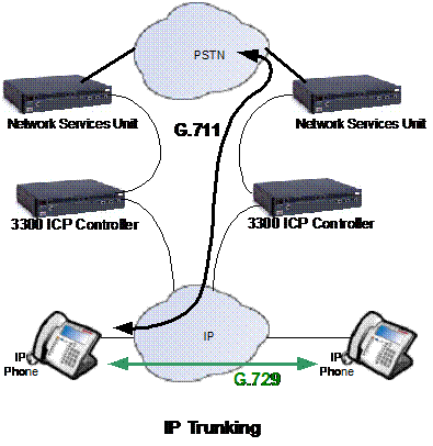
Transcoding is seen as the changing of voice information sent with one CODEC type into that from a different CODEC. However, most CODEC devices rely on G.711 as the base entry level. Thus, transcoding could be seen as going from G.729 to G.726, but this is likely to be via G.711. Compression is seen as simply reducing the amount of data, and in the voice world this could be achieved by going from G.711 to G.729, for example. The terms are often used interchangeably.
Any form of voice compression works by removing a certain amount of information which it deems to be non-essential. This may include not sending data during silence periods as well as sending only the main frequency elements of the voice rather than the full bandwidth. The result of this is that some information will always be lost. Compressed voice will therefore never be as good as uncompressed voice, but the main requirement is to carry the intelligibility. Of the compression CODECs seen, G.729 has good bandwidth reduction as well as maintaining a good voice quality and intelligibility.
In the LAN environment where bandwidth is 'plentiful' there is probably little reason to compress voice, and so G.711 will normally be the CODEC of choice. In a WAN environment, where access bandwidth may be limited, use of the G.729 CODEC could increase the amount of voice traffic that can be carried on a particular link. There may be instances where G.711 is still preferred, for voice quality, but this will limit the voice traffic of the link.
The best network configuration is to be entirely switched. This allows full network bandwidth to be made available to the end user and greatly reduce collisions with a resulting network utilisation decrease, i.e. making more bandwidth available for another application, such as voice!
A Hub works by sharing bandwidth between a number of devices. They 'fight' each other for access. The devices that fail to get access need to wait for an available slot. Hubs also don't implement any form of QoS control. Where data needs to be sent in a timely manner, there is a high probability of introducing unnecessary jitter with potential packet loss.
In a switched environment, all ports can pass data to a LAN switch. Data is passed to queues and priority can be given to types of data, such as those marked by IEEE8021.p/Q tags. Where two devices share a common LAN switch they can effectively pass data to each other at high speed as though they were the only devices on the network, whilst other devices could equally be doing the same. Use of a switch is almost the same as having multiple networks. Network efficiency is greatly improved, as well as network management.
Since connections in a switched network are typically point to point, there is also the possibility of configuring the connection to be Full Duplex. This virtually doubles the bandwidth, since data can be sent and received at the same time. In a half duplex environment data can only be sent or received sequentially. Equipment configured with 'auto-negotiation' will always determine the highest possible data rate and make that available on a connection by connection basis. Simple hubs are generally 'bottom of the shop', fixed at 10BaseT half duplex.
Networks usually consist of different layers. The two main parts are the 'core' network and the 'access' network.
The 'core' network will potentially have data on dedicated links at 1Gbits/s or even higher. The switches at this level will probably include some Layer2 and Layer3 switching and will agglomerate a number of sub-nets onto one, or a small number of units. These units will almost certainly have UPS backup and will be cross-connected in redundant configurations, such that failure of one device is unlikely to result in total network failure.
The 'access' network connects to the core units by single or multiple connections. It provides the slower 10/100BaseT type of connections to the user. These may be cross-connected within geographic locations. If a device fails here, then only the locally connected devices will fail. These units may or may not have UPS backup. This should be considered when voice devices are connected to these access devices.
Ideally the MITEL 3300 ICP controller should have a connection higher up in the network, located more towards the core than at an access point.
A number of areas affect voice quality of service. In the IP world these are primarily:
End to End Delay
Jitter, or delay variation
Packet Loss
Due to link congestion resulting in discarded or out of sequence packets
Due to forced loss of packet due to excessive jitter
Assuming that jitter and packet loss are taken care of, the one parameter left that affects the voice and conversation quality is end-to-end delay. From ITU-T recommendations (and practical experience) the end-to-end delay for a voice call should not exceed 150ms. The characteristics of the end devices such as the gateway (Ethernet and TDM bridge in the 3300) and the IP-Phones are known.
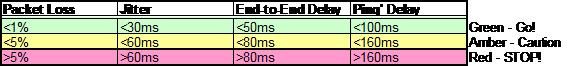
So,
in assessing a network the following network limits should be considered:
'
Other tools, such as network analysers can also be used to determine packet loss. Many now look for VoIP and RTP packets, and can identify when a packet is missing as well as average jitter.
A MITEL IP-Phone is capable of providing a number of CODEC types. These currently include:
G.711 : Same as TDM, both A-Law and u-Law
G.729a
Typically the G.711 CODEC provides the best voice quality and is comparable to TDM type connections. G.729a provides a good reduction in bandwidth with only minor loss in voice quality. Typically G.711 would be used where bandwidth is available, such as in a LAN environment, whereas G.729a would be used in a WAN access environment, where bandwidth is not so readily available.
The table, below, shows typical wire data rates for different protocols and LAN/WAN interfaces. Note, for example, that a Half-Duplex link uses twice the bandwidth on the connection than a similar Full Duplex connection for the same voice connections. This is because the Half-Duplex connection is shared with other devices and one transmitter must also send data on the receive path for all other devices to hear.
From the statement some recommendations ensue:
Use Full Duplex wherever possible. This requires point to point connections
Use a switched environment, rather than hubs
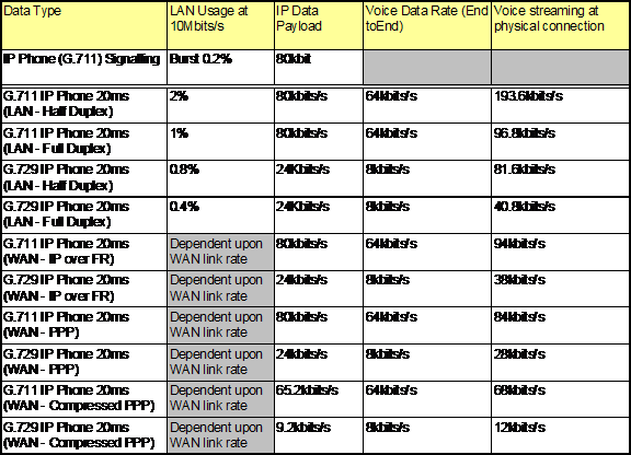
As we can see from the table the physical 'wire' bandwidth required by the IP-Phone is typically:
G.711: about 100kbits/s
G.729: about 40kbits/s
What is wire bandwidth? This is what you pay for.
How is this different from IP (data payload) bandwidth? IP is a number of layers removed from the real connection. It encapsulates the data with routing and address information. It is the basis on which other protocols are then added, such as Frame Relay or Ethernet, to get the data physically moved around, i.e. each of these protocols adds its own overhead on top of the fixed IP bandwidth. See section Network Priority for more detail on the frame breakdown for Ethernet. Compare IP bandwidth in the table above with the real wire bandwidth requirements.
The selection of the CODEC to use on a particular connection can be dependent upon a number of issues, including:
Voice Quality expected by the user
Available bandwidth, especially on a WAN link
Number of devices on a link, and how many are active based on traffic, see section 4.2 below
The voice quality of the CODECs available is usually expressed in terms of a Mean Opinion Score (MOS). The scores range in value from 0 to 5. Typically, anything above 4 is considered as acceptable speech quality. Some typical MOS scores for the CODECs is shown in the table below:
|
CODEC Type |
MOS |
LAN Bandwidth |
|
G.711 |
~100kbits/s |
|
|
G.729 |
~40kbits/s |
As can be seen the G.711 CODEC gives the better speech quality, but also requires more bandwidth in order to achieve this. For this reason it may be desirable to use the G.711 CODEC in a LAN environment, but switch to G.729 in a WAN access connection. In the MITEL 3300 ICP the switch of CODEC can be configured through 'Compression Zones' under 'IP-Trunking'.
When a link is advertised at a particular rate, this is the 'speed' at which the data travels. It is not necessarily the available data rate. In practice, a percentage of this bandwidth is lost due to communication between end devices and because the data is asynchronous and requires certain guard bands. In a synchronous telecom link these issues are taken care of through mechanisms such as framing data into fixed time-slots.
This results in some simple guidelines for LAN and WAN links:
|
Data Connection Type |
Percentage of Bandwidth Available |
Example |
|
LAN - 10BaseT Half Duplex |
10Mbits/s => 4Mbits/s available |
|
|
LAN - 10BaseT Full Duplex |
10Mbits/s => 8Mbits/s available |
|
|
LAN - 100BaseT Half Duplex |
100Mbits/s => 40Mbits/s available |
|
|
LAN - 100BaseT Full Duplex |
100Mbits/s => 80Mbits/s available |
|
|
WAN - 1.5Mbits/s Frame Relay without QoS mechanism in Router |
1.5Mbits/s => 600kbits/s available |
|
|
WAN - 1.5Mbits/s Frame Relay with QoS mechanim in Router |
1.5Mbits/s => 1.05Mbits/s available |
This also leads to some simple guidelines for LAN connections (assuming that all the available bandwidth is used for voice traffic only):
|
Cable Capacity |
Bandwidth % |
Phone Usage at G.711 |
"Voice Channels" G.711 |
"Voice Channels" G.729 (x 2.5) |
|
10BaseT Half | ||||
|
10BaseT Full | ||||
|
100BaseT Half | ||||
|
100BaseT Full |
This is the maximum capability of a LAN link assuming that the link is used purely for voice traffic. If the link is shared with other devices, such as PCs, then some priority mechanism will be needed to ensure that the voice gets the available bandwidth when needed. Also, in a busy network with multiple broadcasts the available bandwidth will reduce by this percentage. For example, in a network with 10% broadcast traffic (at 10Mbits/s) the 40% available bandwidth will reduce to 30% for a half-duplex link, and the number of 'voice channels' accordingly.
Why is the ratio from half-duplex to full duplex four and not two? Well conversations need both a talk and a listen path. And, for half duplex both paths share the same physical wire, whereas for full duplex both send and receive can occur simultaneously on different wire pairs.
Thus for half-duplex the channel availability is 10M x 40% / (2 x 100k) = 20 channels. Only 40% of the bandwidth is available due to collisions and the collision avoidance mechanisms. For full duplex connections there are no collisions, so utilisation can double to 80%. Also there are separate paths for send and receive data, so only half the connection bandwidth is used. Thus 10M x 80% / (1 x100k) = 80 channels.
A WAN link is generally point to point between routers and so is always a full duplex link. The link speed for access WAN connections are also slower, so the number of available 'voice channels' is reduced.
So, for example a 1.5Mbits/s link might support the following number of 'voice channels':
|
Cable Capacity |
Bandwidth % |
"Voice Channels" G.711 |
"Voice Channels" G.729 (x 2.5) |
|
1.5Mbits/s without QoS mechanism | |||
|
1.5Mbits/s with QoS mechanism |
When a WAN link is shared with other data devices there are other considerations including the introduction of waiting delay. The end device sees this as jitter resulting in potential packet loss and the user experiencing voice quality degradation. All these need to be considered.
Serialisation delay is due to the fact that data is queued in a particular device, but cannot be sent because another packet is currently being sent. In a fast link, such as in the LAN, this delay is fairly small (orders of a few milliseconds) and is easily taken care of with the end-device jitter buffer.
However, in a WAN access connection, the data rate is potentially not as high as within the LAN. In this case the waiting delay increases as the data rate reduces. If a particularly large packet (1500 bytes) is being sent, then other devices must wait until that has gone before they can get access.
The IP-Phone and gateway devices are capable of handling delay variations up to 30ms, but this is the limit. A more reasonable working limit is 20ms. The following chart shows waiting delay against link speed as well as against MTU.
From the graph, below, it can be seen that when a packet of 1500 bytes is sent, in order to meet the 20ms ideal working position, that a data-rate of about 700kbits/s is needed.
Through modifying the router MTU value to 500, larger packets will be cut down and sent in smaller chunks. The result of this is that there are three times as many opportunities to send the voice data. Thus the data rate link could be reduced to 300kbits/s.
Beware, as some packets may not allow MTU to cut them down. Video may be one of these. In this case the router with the lower MTU could reject these packets, effectively denying access.
Although the data rates above are minimum recommendations, slower speeds have been used. However, these involve links with strict control of priority queuing and may involve physical restrictions such as available for PC or Phone but not both simultaneously.
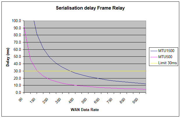
For slower speed links then the recommendation is to reduce the MTU in the routers/gateways to provide more opportunity for the voice traffic. A value of 500 has been found to work well.
There are two areas where priority mechanisms operate in the network to ensure that voice traffic maintains high priority. These are:
Layer 2 in the LAN through use of IEEE802.1p/Q
Layer 3 in the WAN through use of DiffServe/TOS/Precedence
The picture blow highlights an Ethernet packet format, and the location of the Layer 2 Priority and Layer 3 Priority fields. This view is of a Tagged frame, since it included IEEE802.1p/Q information.
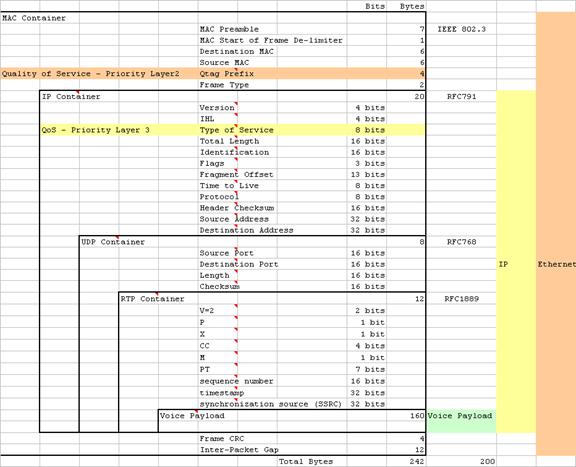
The priority mechanism used relies on that described in IEEE802.1p. This is a sub-section of IEEE802.1Q also known as VLAN tagging.
One potential issue is the different ways in which these specifications have been interpreted. There are a number of switches appearing on the market that provide VLAN capability, but these may not use all of the sections specified in 802.1Q. The method of configuring the switch ports may also differ.
The main requirements are thus:
Ports should be configurable to provide VLAN tagging to incoming untagged information and remove this tagging when passing out of the switch. This is used by the controller and associated applications
Ports should be configurable to pass all active VLANs with tagging from one switch to another; i.e. there is no untagged information present in the connection. This is used between LAN switches and maintains priority information between units.
Ports should be configurable to accept untagged information, pass this on to a specified VLAN, as well as accepting tagged information. The port should also strip off tagging for data from a specific VLAN, but not strip data from other VLANs. This is used when connecting the dual port phones and PCs to the network.
Some other VLAN guidelines for use with voice include:
Additional bandwidth is always good!
Use full duplex wherever possible
Don't use VLAN 0
Set Priority to value 6 for voice
Set Priority for untagged VLAN/native VLAN/default_vlan to 0
Hubs don't support priority queuing, so use Layer2 switches with 802.1p/Q support
This is data collected from the command line interface (RS232 connection)
This mode allows untagged information to be placed onto a specific VLAN as well as passing VLAN tagged data for other VLAN. Typically this configuration would be used to connect to a dual port phone with an attached PC (no VLAN).
>switchport trunk encapsulation dot1q
>switchport trunk native vlan 193
>switchport mode trunk
>spanning-tree portfast
This configuration is for the dual port phones. It can be seen that the port will provide VLAN tagging through the first command line, and that the encapsulation type is to IEEE802.1Q (dot1q). Cisco also supports a similar scheme of priority with ISL encapsulation, but this is proprietary so will not inter-work with other vendor equipment.
The port is configured such that untagged information will be directed to (native) VLAN193.
The port is considered as a trunk due to the fact that it handles multiple VLAN connections.
The last command indicates that this port will not be closed down during spanning tree operations. It is left to the network engineer to ensure that there are no network loops behind this connection. (This command would typically be used when connection is to a server or the main controller).
This interface will not accept VLAN tagged information, but will add tagging information to data between the access port and VLAN712 (in this case the voice VLAN). This would be used for the 3300 ICP controller, or for an application such as Speak at Ease.
>interface FastEthernet0/19
>switchport access vlan 712
>spanning-tree portfast
Other commands will allow the individual port priority to be specified. In the case of the access port, the 'encapsulation' method is specified elsewhere.
Whilst, the IEEE specification allows for VLANs from 0 to 4095 not all vendors support this range. As a general rule VLAN 0 is treated in different ways by different vendors. The recommendation is not to use VLAN0. Cisco also reserves VLAN 1000 upwards for its own purposes, so these are also not recommended for use.
Cisco devices provide this as another port configuration. However on some of the devices it is not possible to use this and 'Trunk' ports on the same unit. Unfortunately, the multi-VLAN port type is needed in order to work with other vendor products. A 'Trunk' port can be used, but it will also remove tagging from the configured native VLAN, which may not be what is required. There are two possible ways out of this situation:
Run ISL between the two units, but then they both need to be Cisco
Create a dummy VLAN that is not used anywhere else in the network. This will ensure compatibility with other vendor units and allow products to be mixed.
The HP switch uses a similar RS232 connection, but the user interface is more menu-driven. This makes the configuration much more intuitive. A typical screen display is shown:
Actions-> Back Add Edit Delete Help
Port DEFAULT_VLAN voice_vlan data_vlan test4
------------ ------------ ------------
1 | Untagged Tagged No No
2 | Untagged Tagged No No
3 | Untagged Tagged No No
4 | Untagged Tagged No No
5 | Tagged Tagged Tagged No
6 | No No No Untagged
7 | No Untagged No No
8 | Untagged No No No
9 | Untagged No No No
10 | Untagged No No No
11 | Untagged No No No
12 | Untagged No No No
The default_vlan is VLAN1. The VLAN numbers have been assigned names to help follow which function is assigned to which VLAN. The 'voice_vlan' is VLAN2, the 'data_vlan' is VLAN3 and 'test4' is VLAN4.
The IP devices that would be connected to the port examples above would be:
Ports 1 to 4: Dual port phones with PCs.
Port 5: Interconnect between network switches.
Port 7: MITEL 3300 ICP controller, or similar voice applications such a Speak at Ease.
Ports 8 to 12: Connect only to PCs.
In common with many switch vendors it is not recommended to use VLAN0 with HP. However it is possible to extend the VLAN numbering up to the maximum of 4095.
There are a number of different WAN technologies to provide data routing with different priorities and service level agreements. Most of these deal with the WAN technology, but most rely on information being presented in the Layer 3 Type of Service field.
The Type of Service field has undergone some name changes as well as additional functions. This field is now also covered as DiffServe, or Differentiated Services. The DiffServe uses the precedence and some of the TOS bits (TOS instead of Type of Service field) to provide 64 different services. See the diagram in section above to find the location of Type of Service field.
The MITEL 3300 ICP controller and IP-Phones use the Type of Service format for priority and TOS. This complies with RFC791, but also by choice of value, RFC1122 and RFC1349.

The precedence field is similar in operation to the IEEE802.1p field, and in fact many routers offer the capability of mapping between the two schemes. Once a TOS and precedence is chosen it never changes. Therefore the voice application sets the appropriate values before data is sent. Voice applications are fixed with a value of 0xB0 for the Type of Service field. This provides a precedence of 5 with minimum delay.
All that is required is that the router device support priority queuing mechanisms, such as Weighted Fair Queuing.
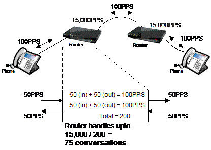
With
a Layer 3 device, such as a router, the packet per second (PPS) throughput is also important. With an
IP-Phone the frame rate is every 20ms. This means that the phone will send 50
packets per second and will also receive 50 packets per second. Beware though
how vendors might specify the PPS rating. For example, with two phones connected
to a router each port will send and receive 50PPS. That's 100PPS per port,
requiring that 200PPS to be handled.
However, between the phones only 50PPS went one way and 50PPS in the return
direction. So, throughput was 100PPS.
In this diagram the Router has a handling capacity of 15,000PPS. Throughput would be half this number.
The following network diagram highlights the use of the Dual Port Phones and the configuration of a network including VLAN priority and also the use of Diffserve/TOS in the WAN connection.
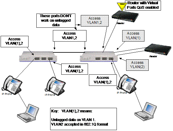
In the diagram, the network switch ports connected to the Dual Port Phones must be able to accept both untagged information and tagged information. The untagged data will then be translated to a 'data' VLAN (1), whereas the voice will be destined for a Voice VLAN (2). In the outgoing direction, these ports must also pass information from the Voice VLAN still tagged, but traffic from the 'data' VLAN must be sent untagged for the devices that are incapable of handling VLAN information.
The requirement to use VLAN and priority queuing becomes obvious when both 'data' and Voice information must share a link between units within the network. In this case it is important that the deterministic voice information gets priority over the non-deterministic 'data' traffic. This is where the IEEE802.1p comes into play, and IEEE802.1p is a subset within IEEE802.1Q.
Routers, or Layer3 switches, involved in segmenting the network will also need connections into the different VLANs. Each VLAN will be identified by a VLAN number, but also by the unique sub-net address. In this way the routers and Layer3 switches that are unaware of VLAN can still pass data between the VLANs. In this case it is required that a separate physical connection be made to each VLAN, and that the ports on the Layer2 switch only pass information to and from one specific VLAN. At the Layer2 port, the VLAN information is removed on egress and added on ingress according to the port or VLAN configurations.
Some routers are VLAN aware. These can be considered to include a virtual Layer2 switch within the unit, which then directs data according to the VLAN information. These devices are often referred to as including 'Virtual Ports'. The advantage is that only one physical connection is needed to handle multiple VLANs.
Generally this is a good thing to do, irrespective of whether a voice over IP installation is being used.
Creating a flat network may appear to speed up transactions due to the high link speed, but Layer3 switches are very much hardware oriented today, and give equally good performance as their Layer2 counterparts.
Remember that in the Layer2 switch environment, data can be addressed directly to a specific port hence reducing loading on links not used. However, where the Layer2 devices are unable to identify an address, or port location to use, additional protocols are needed to get this information. These additional protocols generally broadcast data to every port and device. In this instance, the loading on the network is almost back to that of a shared environment. The Layer 2 devices maintain a list of addresses and port location in internal memory. If the list is small, then the level of broadcasts can also increase since new information is rapidly 'aged' out of the list.
Hence a large flat network can potentially grind to halt, not because of genuine traffic loading, but simply due to the amount of broadcast traffic that will be needed. Using subnets helps by segmenting broadcast domains. The Layer2 devices subsequently need to hold less information, and so broadcast less often.
Therefore including Layer3 devices will improve speed within communities of interest and the overall network, as well as reducing the burden on the system to all the broadcast traffic. It is also a requirement for VLANs to operate correctly and provide the voice priority that is required when using Dual Port Phones.
This area could be considered as the signalling quality of service. It is a measure of how long a user needs to wait before a service becomes available, or whether the user becomes blocked from using a function. Examples of this would be delay in receiving dial tone, or blocking that could occur if there are insufficient PSTN trunks.
As the system grows, and more traffic is presented, it has to deal with an ever-increasing number of tasks. The end result of this is that feature interaction becomes slower. The ICP systems are engineered to ensure that with different combinations of devices services are still maintained within normal working parameters. The exact details are not captured here, but are specific to particular releases, since changes in software or hardware have a bearing on the results.
In terms of calculating some of these limitations a good guideline has been to use the PI numbers from SX2000 and add 10% overhead for IP devices.
The largest effect on performance and availability is the level of traffic that the units need to handle. There are a number of areas that are affected by traffic. These include:
Trunks to PSTN
E2T (Gateway) channels
DSP channels
LAN blocking between devices
WAN blocking between end points
The traffic guidelines used in calculating the system performance are based on:
Standard busy office traffic : 6CCS (about 6 calls per hour)
ACD : 27CCS (about 27 calls per hour)
36CCS = 1 erlang = 3600 call seconds during the busy hour.
Traffic is split roughly 65% to and from trunks, with the remainder internal or intercom traffic.
Traffic blocking is calculated using ErlangB formula
Traffic blocking probability for internal/intercom traffic is P.001 (1 in 1000 calls blocked)
Traffic blocking probability for trunk traffic is P.01 (1 in 100 calls blocked)
For TDM traffic it is possible to calculate the amount of traffic that needs to be presented in terms of CCS and match this to a number of trunk channels. In the IP world fixed channels do not exist, so this calculation becomes a little trickier.
In calculating the amount of traffic that can be handled over a LAN or WAN link, the bandwidth calculations in section 3.6 Available Bandwidth can be applied. From these it is possible to work out a number of 'voice channels' and hence assign a particular CCS rating.
In this example we will assume the following configuration:
There are 50 IP Phones at the corporate centre
There are 10 IP phones over a T1 link at a remote site
Trunk traffic is 65% of all traffic
Traffic between remotely located IP phones stays local to the remote site, i.e. it does does not traverse the WAN link
|
Calculation |
Formula |
Result |
|
Remote Phones |
| |
|
Total CCS at remote site |
Remote phones x 6CCS |
60CCS |
|
Percentage trunk traffic |
Total CCS x 65% |
39CCS |
|
Percentage intercom traffic |
Total CCS x (100 - trunk traffic)% |
21CCS |
|
Local Intercom Traffic |
Intercom traffic x Ratio of local phones / total phones (21 x 10 / 60) |
3.5CCS |
|
Total traffic over WAN |
Total traffic - local traffic |
56.5CCS |
Thus:
The total traffic handled is 60CCS.
3.5CCS is local traffic
WAN traffic is therefore: 56.5CCS = 60 -3.5
From an earlier calculation it was highlighted that a T1 WAN link could handle 6 G.711 'voice channels'. From ErlangB tables with P.001 blocking such a link can handle 41.1CCS. There is therefore a mismatch between presented traffic and carrying capacity.
Solutions that come from this can then be covered by:
Use compression (G.729) to the remote phones. This increases the 'voice channel' capability. However it also reduces voice quality, which may not be acceptable.
The WAN link bandwidth could be increased
The blocking ratio could be changed to P.01, such a link would handle 68.8CCS
The number of remote phones could be reduced, or the overall number of phones could be reduced.
These are all potential solutions and each may have to be investigated to understand the nature of the installation. Doing this calculation up front ensures that such issues are highlighted before equipment is bought and installed.
The IP-Trunking is a form of networking that allows traffic from different controllers to be passed between them. This provides the ability to build larger systems, as well as combining systems in different geographic locations as a single system.
Where LAN/WAN connections exist between nodes, then this medium can be used to pass traffic. A limit on the number of conversations is set on this connection. In the event this limit is exceeded, an alternative path will be tried, be it via a different node connected via IP, or alternatively through the PSTN TDM network.
The issue is what trunk restriction value to set for a particular connection. This relies very much on traffic and also the bandwidth calculations, such as those carried out in earlier sections.
Since the bandwidth is derived from the number of conversations it is important to understand which CODEC will be used across the link. Is it exclusively G.729, or G.711 or a combination of both?
Also, the level of networking between nodes needs to be understood and whether this includes PSTN trunk traffic or only internal intercom traffic.
As a general guideline we can consider that a single node might have a high networking traffic ratio of 15%. For a particular node with a number of devices, the amount of traffic to and from this node will remain essentially constant. What will differ, will be the level of traffic destined for another particular node. For example, 15% of traffic might be destined for the second node in a two-node system, but 7.5% will be destined for each the other two nodes in a three-node system. Obviously in the second scenario less bandwidth will be needed per to and from a particular node, but the total per node will remain about the same.
Consider the following example:
Two equal sized systems
Exclusively 250 IP devices/phones
Calls from TDM, or to TDM devices including trunks, use G.711 CODEC
Calls between IP devices use the G.729 CODEC
Traffic is typically 35% (100-65) internal, the remainder to and from PSTN trunks
Calls internally are typically 50% outgoing and 50% incoming
Traffic is rated at 6CCS per device
Traffic between nodes is 15%
Doing some simple calculations below:
|
Calculation |
Formula |
Result |
|
Traffic from IP sets |
Number of sets (250) x 6CCS |
1500CCS |
|
Percentage networked |
Total traffic x 15% |
225CCS |
|
Percentage traffic intercom |
Networked traffic x 35% |
79CCS |
|
Percentage traffic trunk to PSTN |
Networked traffic - intercom traffic |
146CCS |
|
Total Number of IP Trunk channels needed |
ErlangB on total IP trunk traffic (225CCS) |
13 Channels (P.01) |
|
Number of channels needed for PSTN Trunks (G.711) |
ErlangB on PSTN trunk traffic (146CCS) |
10 Channels *1 (P.01) |
|
Number of channels needed for Intercom/Internal traffic (G.729) |
ErlangB on Intercom traffic (79CCS) |
7 Channels *1 (P.01) |
|
Bandwidth needed (use worse case) |
Number of G.711 channels (10) x 100k + [Total number of channels (13) - PSTN trunk channels(10)] x 40k |
1120kbits/s |
|
WAN Bandwidth Required |
Assume with QoS so / 70% |
1600kbits/s |
|
Number of channels for IP Trunk |
Total number of channels |
13 Channels |
*1 Note: The number of channels needed purely for internal traffic is 7. For external traffic the total number is 10. However, together the total is only 13. How is this so? The reason is that a number of channels will have shared use, in this case it must be 4 (10+7-13). The higher G.711 rate is used to ensure adequate bandwidth at all times.
Thus it can be seen that this data rate is pretty close to a typical T1 rate. The option could be to increase the available link rate by upgrading to an E1 link, or multiple T1 links, or accept a lower quantity of IP Trunk calls, i.e. slight reduction in inter-node traffic
The above two sections have dealt with network conditions and call traffic. However, before any of this can occur, the system needs to be installed and the end devices need some code to get them running.
This is the normal sequence of events for a dual port IP Phone, where VLANs are implemented:
Power up
Run 'Boot' code
Request IP address (untagged) through DHCP
Receive IP address from default VLAN (data VLAN) and specific phone and system options
Check VLAN information
Relinquish IP address (untagged)
Request IP address on voice VLAN (tagged)
Receive IP address from voice VLAN and specific phone and system options again
Check VLAN information matches, if not repeat until it is.
Locate TFTP server
Get running code
Register with call control
Go!
The phone does a double fetch of information, so it is important to have the same VLAN and priority information in the DHCP server associated with the data VLAN as it is for the DHCP server associated with the voice VLAN, i.e. copy the option data.
The engineering guideline that can be highlighted here is that this sequence works with either multiple DHCP servers on each VLAN, or that the router/Layer3 switch connecting the VLANs has DHCP forwarding capability.
Some options also exist to improve system start-up time. To improve phone download time, especially when a number (currently more than 400) of IP-Phones are associated with a controller, an external TFTP server, such as an NT server can be used. In the DHCP server, used by the phones, just alter the TFTP IP address to match and copy the download files onto the TFTP server. In this way multiple downloads can occur in parallel reducing system start-up time after a re-boot.
The sequence above assumes that the phones will get information from a DHCP server. There is also the possibility to manually programme up the IP-Phone with the same information as it starts to boot up. In this way the information is fixed, and requires little DHCP intervention. This method can be particularly useful where a phone is used on a remote WAN link and the router cannot forward DHCP requests, or where a local DHCP server does not exist. It can also be useful where VPNs are employed, for much the same reasons, that DHCP forwarding may not be available.
The sequence involves bringing up the RTC where call control lives. In this is included the DHCP and TFTP servers. In parallel the E2T is also 'brought into life' and a couple of the DHCP of options are used to identify the download code for this unit.
It is recommended that the 3300 ICP controller DHCP server be used locally within the controller for devices on the voice VLAN. This can be disabled, but would then require an external DHCP server to service devices on the voice VLAN.
The DHCP options to use within the DHCP server may differ from product release to product release, so it is recommended that the associated documentation for the product and release be consulted.
As an overview, the options currently used are shown here (product documentation is master):
|
DHCP Option |
Information |
|
003 - Router Address |
IP Address, e.g. 192.167.22.251 |
|
066 - FTP IP address (same as option 129), for E2T |
IP Address, e.g. 192.167.22.10 |
|
067 -Name of file on FTP server |
"bootfile" |
|
128 - (Specific) TFTP Server |
IP Address, e.g. 192.167.22.10 |
|
129 - (Specific) RTC |
IP Address, e.g. 192.167.22.10 |
|
130 - (Specific) IP Phone Load |
"MITEL IP PHONE" |
|
132 - (Specific) VLAN ID (32 bit) |
0x2 |
|
133 - (Specific) Priority (32 bit) |
0x6 |
To allow users to move off the local sub-net, or to let new people join a subnet, a method is needed to give up an IP address and also obtain a new address. If a phone is disconnected it obviously cannot talk to the DHCP server, so another method is needed to free up unused addresses. This is the DHCP lease time. This helps provide the Dynamic in DHCP by clearing out unused IP addresses and making them available for new requests.
The timer can be set from a few minutes to weeks. Typically 30 minutes is a good time. It reduces the amount of checking to see if an IP address is still in use, as well as providing a reasonable recovery time to free up any unused addresses.
|
Politica de confidentialitate | Termeni si conditii de utilizare |

Vizualizari: 1720
Importanta: ![]()
Termeni si conditii de utilizare | Contact
© SCRIGROUP 2025 . All rights reserved