| CATEGORII DOCUMENTE |
| Bulgara | Ceha slovaca | Croata | Engleza | Estona | Finlandeza | Franceza |
| Germana | Italiana | Letona | Lituaniana | Maghiara | Olandeza | Poloneza |
| Sarba | Slovena | Spaniola | Suedeza | Turca | Ucraineana |
Understanding various types of Stepper Motors
And
Controlling it through
Content
Theory 3
Stepper Motor 3
i. Definition 3
ii. Characteristics 3
iii. Working 4
iv. Stepping Modes 6
b. Parallel Port 8
The Circuit 11
Programming 14
a. The Accessing I/O Ports under NT/2000/XP 14
b. The Program code in VB 15
c.
d. The Program Code in Unix environment In C 19
AIM :- To understand and run a stepper motor through PCs parallel port Interface.
THEORY
1. STEPPER MOTOR
In Theory, a Stepper motor is a marvel in simplicity. It has no brushes, or contacts. Basically it's a synchronous motor with the magnetic field electronically switched to rotate the armature magnet around.
Definition
A stepper motor is basically an electromechanical device which converts electrical pulses into discrete mechanical movements. The shaft or spindle of a stepper motor rotates in discrete step increments when electrical command pulses are applied to it in the proper sequence. The motors rotation has several direct relationships to these applied input pulses. The sequence of the applied pulses is directly related to the direction of motor shafts rotation. The speed of the motor shafts rotation is directly related to the frequency of the input pulses and the length of rotation is directly related to the number of input pulses applied.
Characteristics:
Holding Torque - Steppers have very good low speed and holding torque. Steppers are usually rated in terms of their holding force (oz/in) and can even hold a position (to a lesser degree) without power applied, using magnetic 'detent' torque.
Open loop positioning - Perhaps the most valuable and interesting feature of a stepper is the ability to position the shaft in fine predictable increments, without need to query the motor as to its position. Steppers can run 'open-loop' without the need for any kind of encoder to determine the shaft position. Closed loop systems- systems that feed back position information, are known as servo systems. Compared to servos, steppers are very easy to control; the position of the shaft is guaranteed as long as the torque of the motor is sufficient for the load, under all its operating conditions.
Load Independent - The rotation speed of a stepper is independent of load, provided it has sufficient torque to overcome slipping. The higher rpm a stepper motor is driven, the more torque it needs, so all steppers eventually poop out at some rpm and start slipping. Slipping is usually a disaster for steppers, because the position of the shaft becomes unknown. For this reason, software usually keeps the stepping rate within a maximum top rate. In applications where a known RPM is needed under a varying load, steppers can be very handy.
Working:
The stepper motor uses the theory of operation for magnets to make the motor
shaft turn a precise distance when a pulse of electricity is provided. You
learned previously that like poles of a magnet repel and unlike poles attract.
Figure 1 shows a typical cross-sectional view of the rotor and stator of a
stepper motor. From this diagram you can see that the stator (stationary
winding) has four poles, and the rotor has six poles (three complete magnets).
The rotor will require 12 pulses of electricity to move the 12 steps to make
one complete revolution. Another way to say this is that the rotor will move
precisely 30 for each pulse of electricity that the motor receives. The number
of degrees the rotor will turn when a pulse of electricity is delivered to the motor
can be calculated by dividing the number of degrees in one revolution of the
shaft (360) by the number of poles (north and south) in the rotor. In this
stepper motor 360 is divided by 12 to get 30.
Figure 1. Diagram that shows the position of the six-pole rotor and four-pole stator of a typical stepper motor
When no power is applied to the motor, the residual magnetism in the rotor magnets will cause the rotor to detent or align one set of its magnetic poles with the magnetic poles of one of the stator magnets. This means that the rotor will have 12 possible detent positions. When the rotor is in a detent position, it will have enough magnetic force to keep the shaft from moving to the next position. This is what makes the rotor feel like it is clicking from one position to the next as you rotate the rotor by hand with no power applied.
When power is
applied, it is directed to only one of the stator pairs of windings, which will
cause that winding pair to become a magnet. One of the coils for the pair will
become the north pole, and the other will become the south pole. When this
occurs, the stator coil that is the north pole will attract the closest rotor
tooth that has the opposite polarity, and the stator coil that is the south
pole will attract the closest rotor tooth that has the opposite polarity. When
current is flowing through these poles, the rotor will now have a much stronger
attraction to the stator winding, and the increased torque is called
holding torque.
By changing the current flow to the next stator winding, the magnetic field will be changed 90. The rotor will only move 30 before its magnetic fields will again align with the change in the stator field. The magnetic field in the stator is continually changed as the rotor moves through the 12 steps to move a total of 360. Figure 2 shows the position of the rotor changing as the current supplied to the stator changes.
FIGURE 2 Movement of the stepper motor rotor as current is pulsed to the stator. (a) Current is applied to the top and bottom windings, so the top winding is north, (b) Current is applied to left and right windings, so the left winding is north, (c) Current is applied to the top and bottom windings, so the bottom winding is north, (d) Current is applied to the left and right windings so the right winding is north.
In Fig. 2a you can see that when current is applied to the top and bottom stator windings, they will become a magnet with the top part of the winding being the north pole, and the bottom part of the winding being the south pole. You should notice that this will cause the rotor to move a small amount so that one of its south poles is aligned with the north stator pole (at the top), and the opposite end of the rotor pole, which is the north pole, will align with the south pole of the stator (at the bottom). A line is placed on the south-pole piece that is located at the 12 o'clock position in Fig. 2a so that you can follow its movement as current is moved from one stator winding to the next. In Fig. 2b current has been turned off to the top and bottom windings, and current is now applied to the stator windings shown at the right and left sides of the motor. When this occurs, the stator winding at the 3 o'clock position will have the polarity for the south pole of the stator magnet, and the winding at the 9 o'clock position will have the north-pole polarity. In this condition, the next rotor pole that will be able to align with the stator magnets is the next pole in the clockwise position to the previous pole. This means that the rotor will only need to rotate 30 in the clockwise position for this set of poles to align itself so that it attracts the stator poles.
In Fig. 2c you can see that the top and bottom stator windings are again energized, but this time the top winding is the south pole of the magnetic field and the bottom winding is the north pole. This change in magnetic field will cause the rotor to again move 30 in the clockwise position until its poles will align with the top and bottom stator poles. You should notice that the original rotor pole that was at the 12 o'clock position when the motor first started has now moved three steps in the clockwise position.
In Fig. 2d you can see that the two side stator windings are again energized, but this time the winding at the 3 o'clock position is the north pole. This change in polarity will cause the rotor to move another 30 in the clockwise direction. You should notice that the rotor has moved four steps of 30 each, which means the rotor has moved a total of 120 from its original position. This can be verified by the position of the rotor pole that has the line on it, which is now pointing at the stator winding that is located in the 3 o'clock position.
Types of Stepper Motors:
Stepper Motors come in a variety of sizes, and strengths, from tiny floppy disk motors, to huge machinery steppers rated over 1000 oz in. Three basic types of stepper motors include the permanent magnet motor, the variable re-luctance motor, and the hybrid motor, which is a combination of the previous two.
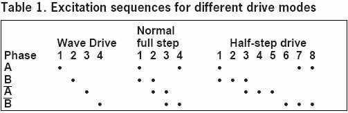
Stepping Modes
The following are the most common drive modes.
Wave Drive (1 phase on)
Full Step Drive (2 phases on)
Half Step Drive (1 & 2 phases on)
Microstepping (Continuously varying motor currents)
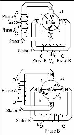
For the following discussions please refer to the figure 9.
In ![]() ->
-> ![]() and the rotor steps from position 8 -> 2 ->4
-> 6. For unipolar and bipolar wound motors with the same winding parameters
this excitation mode would result in the same mechanical position. The disadvantage
of this drive mode is that in the unipolar wound motor you are only using 25%
and in the bipolar motor only 50% of the total motor winding at any given time.
This means that you are not getting the maximum torque output from the motor.
and the rotor steps from position 8 -> 2 ->4
-> 6. For unipolar and bipolar wound motors with the same winding parameters
this excitation mode would result in the same mechanical position. The disadvantage
of this drive mode is that in the unipolar wound motor you are only using 25%
and in the bipolar motor only 50% of the total motor winding at any given time.
This means that you are not getting the maximum torque output from the motor.
 In
In ![]()
![]() and the rotor steps from position 1 ->3 ->5->
7 . Full step mode results in the same angular movement as 1 phase on drive but
the mechanical position is offset by one half of a full step. The torque output
of the unipolar wound motor is lower than the bipolar motor (for motors with
the same winding parameters) since the unipolar motor uses only 50% of the available
winding while the bipolar motor uses the entire winding.
and the rotor steps from position 1 ->3 ->5->
7 . Full step mode results in the same angular movement as 1 phase on drive but
the mechanical position is offset by one half of a full step. The torque output
of the unipolar wound motor is lower than the bipolar motor (for motors with
the same winding parameters) since the unipolar motor uses only 50% of the available
winding while the bipolar motor uses the entire winding.
![]()
![]() and
the rotor steps from position 1 ->2 -> 3-> 4 ->5 -> 6 -> 7 ->
8. This results in angular movements that are half of those in 1- or
2-phases-on drive modes. Half stepping can reduce a phenomena referred to as
resonance which can be experienced in 1- or 2- phases-on drive modes.
and
the rotor steps from position 1 ->2 -> 3-> 4 ->5 -> 6 -> 7 ->
8. This results in angular movements that are half of those in 1- or
2-phases-on drive modes. Half stepping can reduce a phenomena referred to as
resonance which can be experienced in 1- or 2- phases-on drive modes.
The excitation sequences for the above drive modes are summarized in Table 1.
In
Shortcut for finding the proper wiring sequence
For 5 wires 1 is common to be plugged at positive supply and rest four to the pulses. For 6 wires 2 are common to be plugged at positive supply and rest four to the pulses.
Connect the center tap(s) to the power source (or current-Limiting resistor.) Connect the remaining 4 wires in any pattern. If it doesn't work, you only need try these 2 swaps
1 2 3 4 - (arbitrary first wiring order)
1 2 4 3 - switch end pair
1 4 2 3 - switch middle pair
You're finished when the motor turns smoothly in either direction. If the motor turns in the opposite direction from desired, reverse the wires so that ABCD would become DCBA.
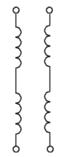
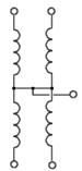
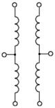
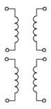
Wiring of stepper motor of different number of wires:
|
4 wires |
5 wires |
6 wires |
8 wires |
Now that we are done with the circuitry for the wiring sequence, and theory of stepper motor, we will build up a circuit through the use of TTL device to get a supply voltage of 12V.this is because, our stepper motor used is a 12V one and the parallel port gives us only 5V. But before that lets discuss how to intract with parallel port.
2. SOME BASICS OF A
What is a port?
A port contains a set of signal lines
that the CPU sends or receives data with other components. We use ports to
communicate via modem, printer, keyboard, mouse etc. In signaling, open signals
are '1' and close signals are '0' so it is like binary
system. A parallel port sends 8 bits and receives 5 bits at a time. The serial
port RS-232 sends only 1 bit at a time but it is multidirectional so it can
send 1 bit and receive 1 bit at a time
Figure
10.
In sending the sequences, you will need the data ports which can be seen in the picture from D0 to D7 .
These ports are made for reading signals.
The range is like in data ports which are S0-S7. But S0, S1, S2 are invisible
in the connector. And S0 is different; this bit is for timeout flag in EPP (
This port usually used for outputting but these can be used for inputting. The range is like in data ports C0-C7 but C4, C5, C6, C7 are invisible in connector. And the address for this is 0x37A
These are (G0 - G7) the pins from 18 to 25 . These are mostly used for completing the circuit. Different pins are required when using all the pins including the inputs.
After these we will be using data ports in experiment because there are reversed pins in control and status ports. Here is an explanation for reversed pins: While you are not sending any signals to the data port it is in closed position like '00000000' so the 8 pins have no voltage on it (0 Volt) .If you send decimal '255' (binary '11111111') every pin (D0-D7) has a +5 Volt On the other hand, if we use control ports, there are reversed pins which are C0, C1 and C3 so while we send nothing to the control port its behaviour is '0100' in binary (decimal '11')
|
Signal |
BIT |
PIN |
Direction | |
|
-Strobe |
C0 |
Output | ||
|
+Data Bit 0 |
D0 |
Output | ||
|
+Data Bit 1 |
D1 |
Output | ||
|
+Data Bit 2 |
D2 |
Output | ||
|
+Data Bit 3 |
D3 |
Output | ||
|
+Data Bit 4 |
D4 |
Output | ||
|
+Data Bit 5 |
D5 |
Output | ||
|
+Data Bit 6 |
D6 |
Output | ||
|
+Data Bit 7 |
D7 |
Output | ||
|
-Acknowledge |
S6 |
Input | ||
|
+Busy |
S7 |
Input | ||
|
+Paper End |
S5 |
Input | ||
|
+Select In |
S4 |
Input | ||
|
-Auto Feed |
C1 |
Output | ||
|
-Error |
S3 |
Input | ||
|
-Initialize |
C2 |
Output | ||
|
-Select |
C3 |
Output | ||
|
Ground |
Ground |
CIRCUIT
Electricity - Lets get some Zzzzzttt zzzzttt
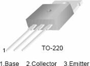
Note- Here the circuit is based on running a stepper motor of 12V (dc), 1.8 DEG/Step, .16A/Phase
Here, we will build up a circuit through the use of TTL device to get a supply voltage of 12V; this is because, our stepper motor used is a 12V one and the parallel port gives us only 5V.
Here I have used
IC ULN2803, which is an 8-bit, TTL-input npn
As Parallel
port is very delicate port attached with mother board, any back current or reverse
emf can blow your entire parallel port along with motherboard off. To prevent
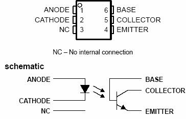
this you need to isolate it through optocouplers. Any optocouplers will serve the purpose and
safeguard the computer. Here I have used IC 4N35.
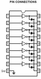
Figure 10. 4N35 IC configuration
Figure 11. IC ULN2803 configuration
The Circuit Diagram:
The simplest circuit diagram with no optocouplers is the figure 12:
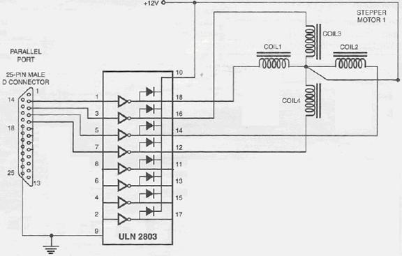
Figure 12. Circuit diagram 1
Enhancing the circuit.
You can add optocouplers for safety of your motherboard. As nobody wants to blow the motherboard through reverse emf sent back or if IC internals get short circuited.
All you need to do is connect the dataport inputs to Anode of IC 4N35 or any optocouplers. Make cathode ground by grounding to any of the ports ground pin.
On the other side, connect the emiiter to to IC and give 5V to the collector.
This will act as a switch between your circuit and parallel port safeguarding it from any damage.
And
If you want to build the circuit
without an IC
C MJE 3055T
What if you want to make your own
Here I show the circuit using very high current gain robust npn transistor Mje 3055T.
MmmI tried to make it on paint, but my mice drawing being very poor I will explain it
Connect the optocpupler input from parallel port as described above.
Now, you dont need additional 5 V supply as you can take 12 V from the other circuit by making these simple changes:
o Connect the emitter of optocoupler to base of transistor.
o Connect the collector of optocoupler to the collector of the transistor.
What this will do is act as a switch. As soon as the photo-diode is activated it infrared light, which falls on the base of optocoupler, making it saturate. It will hence pass current from collector to emitter. This will trigger base of 3055T transistor to go into saturation.
Ground the emitter of 3055T transistor to ground of 12V supply.
Put diodes IN4007 in reverse bias direction from negative and positive supply of 12 V with the collector. That is, positive end in the negative supply and the other to collector. And the negative side of diode to positive supply of 12V and other end to collector just to make sure that any back current doesnt flow.
If you want, put a good capacitor (which can sustain) between negative and positive supply of 12V as a filter in the circuit. I have used 100 Micro F, 63V electrolytic capacitor.
Now all set and done in securing and enhancing the circuit Now connect the common cord of stepper motor to positive supply and rest four into the collector of the transistors.
The Programming part
Before Coding
Mmmm A problem that plagues Windows NT/2000 and Windows XP
Unlike Windows 95 & 98, Windows NT/2000/XP will cause an exception (Privileged Instruction) if an attempt is made to access a port that you are not privileged to talk too. Actually it's not Windows NT that does this, but any 386 or higher processor running in protected mode.
Accessing I/O Ports in protected mode is governed by two events, The I/O privilege level (IOPL) in the EFLAGS register and the I/O permission bit map of a Task State Segment (TSS).
Under Windows NT, there are only two I/O privilege levels used, level 0 & level 3. Usermode programs will run in privilege level 3, while device drivers and the kernel will run in privilege level 0, commonly referred to as ring 0. This allows the trusted operating system and drivers running in kernel mode to access the ports, while preventing less trusted usermode processes from touching the I/O ports and causing conflicts. All usermode programs should talk to a device driver which arbitrates access.
The I/O permission bitmap can be used to allow programs not privileged enough (I.e. usermode programs) the ability to access the I/O ports. When an I/O instruction is executed, the processor will first check if the task is privileged enough to access the ports. Should this be the case, the I/O instruction will be executed. However if the task is not allowed to do I/O, the processor will then check the I/O permission bitmap.
The I/O permission bitmap, as the name suggests uses a single bit to represent each I/O address. If the bit corresponding to a port is set, then the instruction will generate an exception however if the bit is clear then the I/O operation will proceed. This gives a means to allow certain processes to access certain ports. There is one I/O permission bitmap per task.
Accessing I/O Ports under NT/2000/XP
There are two solutions to solving the problem of I/O access under Windows NT. The first solution is to write a device driver which runs in ring 0 (I/O privilege level 0) to access your I/O ports on your behalf. Data can be passed to and from your usermode program to the device driver via IOCTL calls. The driver can then execute your I/O instructions. The problem with this, is that it assumes you have the source code to make such a change.
Another possible alternative is to modify the I/O permission bitmap to allow a particular task, access to certain I/O ports. This grants your usermode program running in ring 3 to do unrestricted I/O operations on selected ports, per the I/O permission bitmap. This method is not really recommended, but provides a means of allowing existing applications to run under windows NT/2000. Writing a device driver to support your hardware is the preferred method. The device driver should check for any contentions before accessing the port.
Well, there are lots of routines, source codes, device drivers, dlls available on the internet who will make your task easy. Like userport1, porttalk, give-io, remove-give-io, inpout32, etc etc.
You can run userport1 routine and get freed, or if you need dlls get ipout32.dll(latest version) and use it.
Now Lets make the code to do the rest
I used inpout32.dll in my application as the Sir (Ram Kishore) who thought me about this knows Visual Basic very well, so I learned VB and worked with him. You can check the workflow below for inpout32.dll and also you can get the source of the dll from the internet.
Note: I am importing
it with the reference of https://www.logix4u.net/ So for further info about the
driver check out the site
The Program
I made the coding in Microsoft Excel VB editor as in excel, it complies automatically and you can make dynamic changes. It doesnt create the exe file, but excel worksheet act as a form.
In Excel go to tool->Macros->VB editor.
In new window, click insert Module.
In module type:
Public Declare Function Inp Lib 'inpout32.dll' Alias 'Inp32' _
(ByVal PortAddress As Integer) _
As Integer
Public Declare Sub Out Lib 'inpout32.dll' Alias 'Out32' _
(ByVal PortAddress As Integer, _
ByVal Value As Integer)
This will call ipout32.dll from system32 directory of your windows, and your
port will also open.
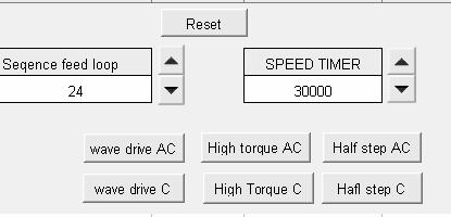
Now create buttons in worksheet
In editor,
Edit buttons as follows
Private Sub CommandButton1_Click()
countit = 0
myTimer = 0
countit = Sheet1.Cells(4, 1)
MsgBox 'Before StartingPlease be Patience as it may take few minutes'
Do While countit > 0
myTimer = Sheet1.Cells(4, 3)
Out 888, 3
Do While myTimer > 0
myTimer = myTimer - 1
myTimer = Sheet1.Cells(4, 3)
Out 888, 6
Do While myTimer > 0
myTimer = myTimer - 1
Out 888, 12
myTimer = Sheet1.Cells(4, 3)
Do While myTimer > 0
myTimer = myTimer - 1
Out 888, 9
myTimer = Sheet1.Cells(4, 3)
Do While myTimer > 0
myTimer = myTimer - 1
countit = countit - 1
Out 888, 0
MsgBox 'Done'
End Sub
Private Sub CommandButton2_Click()
Out 888, 0
End Sub
Private Sub CommandButton3_Click()
countit = 0
myTimer = 0
countit = Sheet1.Cells(4, 1)
MsgBox 'Before StartingPlease be Patience as it may take few minutes'
Do While countit > 0
myTimer = Sheet1.Cells(4, 3)
Out 888, 1
Do While myTimer > 0
myTimer = myTimer - 1
myTimer = Sheet1.Cells(4, 3)
Out 888, 2
Do While myTimer > 0
myTimer = myTimer - 1
Out 888, 4
myTimer = Sheet1.Cells(4, 3)
Do While myTimer > 0
myTimer = myTimer - 1
Out 888, 8
myTimer = Sheet1.Cells(4, 3)
Do While myTimer > 0
myTimer = myTimer - 1
countit = countit - 1
Out 888, 0
End Sub
Private Sub CommandButton4_Click()
countit = 0
myTimer = 0
countit = Sheet1.Cells(4, 1)
MsgBox 'Before StartingPlease be Patience as it may take few minutes'
Do While countit > 0
myTimer = Sheet1.Cells(4, 3)
Out 888, 1
Do While myTimer > 0
myTimer = myTimer - 1
myTimer = Sheet1.Cells(4, 3)
Out 888, 3
Do While myTimer > 0
myTimer = myTimer - 1
Out 888, 2
myTimer = Sheet1.Cells(4, 3)
Do While myTimer > 0
myTimer = myTimer - 1
Out 888, 6
myTimer = Sheet1.Cells(4, 3)
Do While myTimer > 0
myTimer = myTimer - 1
myTimer = Sheet1.Cells(4, 3)
Out 888, 4
Do While myTimer > 0
myTimer = myTimer - 1
myTimer = Sheet1.Cells(4, 3)
Out 888, 12
Do While myTimer > 0
myTimer = myTimer - 1
Out 888, 8
myTimer = Sheet1.Cells(4, 3)
Do While myTimer > 0
myTimer = myTimer - 1
Out 888, 9
myTimer = Sheet1.Cells(4, 3)
Do While myTimer > 0
myTimer = myTimer - 1
countit = countit - 1
Out 888, 0
End Sub
Private Sub CommandButton5_Click()
countit = 0
myTimer = 0
countit = Sheet1.Cells(4, 1)
MsgBox 'Before StartingPlease be Patience as it may take few minutes'
Do While countit > 0
myTimer = Sheet1.Cells(4, 3)
Out 888, 8
Do While myTimer > 0
myTimer = myTimer - 1
myTimer = Sheet1.Cells(4, 3)
Out 888, 4
Do While myTimer > 0
myTimer = myTimer - 1
Out 888, 2
myTimer = Sheet1.Cells(4, 3)
Do While myTimer > 0
myTimer = myTimer - 1
Out 888, 1
myTimer = Sheet1.Cells(4, 3)
Do While myTimer > 0
myTimer = myTimer - 1
countit = countit - 1
Out 888, 0
End Sub
Private Sub CommandButton6_Click()
countit = 0
myTimer = 0
countit = Sheet1.Cells(4, 1)
MsgBox 'Before StartingPlease be Patience as it may take few minutes'
Do While countit > 0
myTimer = Sheet1.Cells(4, 3)
Out 888, 9
Do While myTimer > 0
myTimer = myTimer - 1
myTimer = Sheet1.Cells(4, 3)
Out 888, 12
Do While myTimer > 0
myTimer = myTimer - 1
Out 888, 6
myTimer = Sheet1.Cells(4, 3)
Do While myTimer > 0
myTimer = myTimer - 1
Out 888, 3
myTimer = Sheet1.Cells(4, 3)
Do While myTimer > 0
myTimer = myTimer - 1
countit = countit - 1
Out 888, 0
MsgBox 'Done'
End Sub
Private Sub CommandButton7_Click()
countit = 0
myTimer = 0
countit = Sheet1.Cells(4, 1)
MsgBox 'Before StartingPlease be Patience as it may take few minutes'
Do While countit > 0
myTimer = Sheet1.Cells(4, 3)
Out 888, 9
Do While myTimer > 0
myTimer = myTimer - 1
myTimer = Sheet1.Cells(4, 3)
Out 888, 8
Do While myTimer > 0
myTimer = myTimer - 1
Out 888, 12
myTimer = Sheet1.Cells(4, 3)
Do While myTimer > 0
myTimer = myTimer - 1
Out 888, 4
myTimer = Sheet1.Cells(4, 3)
Do While myTimer > 0
myTimer = myTimer - 1
myTimer = Sheet1.Cells(4, 3)
Out 888, 6
Do While myTimer > 0
myTimer = myTimer - 1
myTimer = Sheet1.Cells(4, 3)
Out 888, 2
Do While myTimer > 0
myTimer = myTimer - 1
Out 888, 3
myTimer = Sheet1.Cells(4, 3)
Do While myTimer > 0
myTimer = myTimer - 1
Out 888, 1
myTimer = Sheet1.Cells(4, 3)
Do While myTimer > 0
myTimer = myTimer - 1
countit = countit - 1
Out 888, 0
End Sub
Also
Turbo C and Borland C/C++ provide access to the I/O ports on the 80x86 CPU via the predefined functions inportb / inport and outportb / outport.
int inportb(int portid); /* returns a byte read from the I/O port portid */
int inport(int portid); /* returns a word read from the I/O port portid */
void outportb(int portid, unsigned char value);
/* writes the byte value to the I/O port portid */
void outport(int portid, int value);
/* writes the word value to the I/O port portid */
|
#include <stdio.h> #include <dos.h> #define Data 0x378 #define Status 0x379 #define Control 0x37a unsigned char Bits; outportb(Data,Bits); /* output data */ Bits = inportb(Status); /* input data */ |
I got a program for same to run in UNIX. I have not checked it, neither I had made. But it has been tested and run. I got it from, Mr. Rachit Rastogi doing final year M.Tech in IS from IIITA. Heres the code
#include<unistd.h>
#include<sys/io.h>
#include<stdio.h>
#include <termios.h>
#include <curses.h>
#include <term.h>
// global data required for terminal settings and char value
static struct termios initial_settings,new_settings;
static char key;
static int stepData[4]=;
static int pos=1;
static int peek_char=-1;
// global data declaring port values
#define DATAPORT 0x378
#define CONTROLPORT 0x37a
//functions declarations
void init_kb();
void close_kb();
void move_right();
void move_left();
void move_forward();
void move_backward();
void stop();
enum mot ;
static enum mot motVal=still;
int kbhit();
int readch();
int main(void)
printf('permission to the port grantedn');
outb(0,CONTROLPORT); //set the mode of the parallel port to write mode
//setuid(uid);
printf('port mode successfully changed to write modenn');
outb(0,DATAPORT);
printf('motor intializedn ');
printf('entering the motor control arean');
while(1)
outb(0,DATAPORT);
close_kb();
exit(0);
// function definitions
void stop()
void move_right()
void move_left()
void move_forward()
void move_backward()
void init_kb()
void close_kb()
int kbhit()
return 0;
int readch()
read(0,&ch,1);
return ch;
|
Politica de confidentialitate | Termeni si conditii de utilizare |

Vizualizari: 2225
Importanta: ![]()
Termeni si conditii de utilizare | Contact
© SCRIGROUP 2025 . All rights reserved