| CATEGORII DOCUMENTE |
| Bulgara | Ceha slovaca | Croata | Engleza | Estona | Finlandeza | Franceza |
| Germana | Italiana | Letona | Lituaniana | Maghiara | Olandeza | Poloneza |
| Sarba | Slovena | Spaniola | Suedeza | Turca | Ucraineana |
How to build a MIDI interface for a SB/SB Pro/SB16:
The SoundBlaster MIDI port uses two pins from the 15-pin joystick port. These normally would be redundant +5volt and ground lines. In the SoundBlaster, there are called MIDI TXD (Transmit eXternal Data) and MIDI RXD (Receive eXternal Data). The signals to and from the SoundBlaster are TTL logic signals. MIDI uses a current loop interface, so the job of the interface box is to convert between TTL-level signals and the MIDI current loop.
If you want
to use the MIDI interface and the SoundBlaster joystick interface
simultaneously, you can make a simple adapter by connecting one male and 2
female 15-pin connectors to a short length of ribbon cable.
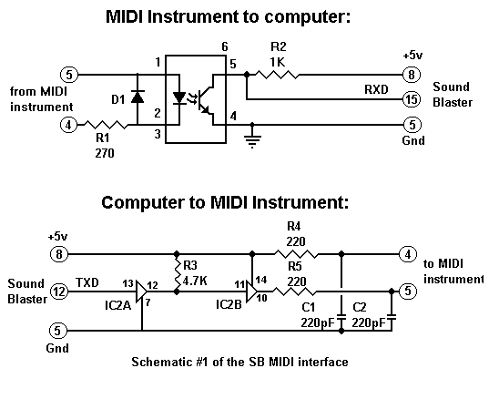
For
simplicity, the schematics show the MIDI input and output circuits seperately,
but they share the +5volt and ground lines. (Pins 8 and 5 on the SoundBlaster).
The interface uses 4-wire shielded cable to connect the computer to the
interface box and two 2-wire sheilded cables to connect the interface box to
the input and output ports on the MIDI instrument.
The MIDI input port only can connect to one instrument, but the MIDI Out from the computer could go to up to 5 MIDI instruments. The schematic diagram only shows one complete MIDI output line. You can connect up to 4 additional MIDI outputs by adding a 220 resistor (from the +5volt pin to pin 4 on the MIDI cable) and a 220 resistor (from the buffer output to pin 5 of the MIDI plug) for each output. You should also add a 220pf capacitor between each additional MIDI line and ground.
Construction:
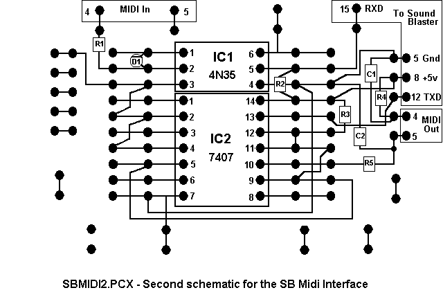
Start with using half of a dual 20-pin IC board, using the first six pins for the optocoupler and the last fourteen pins for the hex buffer. Then remove portions of some of the copper lines on the circuit board with an X-Acto knife, as is shown in the schematic in the SBMIDI2.PCX graphic file.
Cut each trace on both ends first, then remove the copper between the cuts. Now on to component installation! Be sure to use rosin-core solder and a low-wattage soldering iron. Solder the 20-pin socket to the center of the board, being careful not to bridge solder between connections. Then install the other components in the locations shown in the SBMIDI3.PCX schematic.
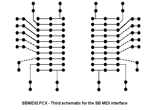
While looking at the SBMIDI3.PCX schematic, note that the ringed end of diode D1 needs to connect to pin1 of the optocoupler. Be sure to run hookup wires from the ground pin on the optocoupler (Pin 4) to the ground pin of the hex buffer (Pin 7) and between pins 11 and 12 on the hex buffer. The remaining hookup wires are optional for additional MIDI outputs. Notice that both a resistor and a capacitor must be connected in the same hole for each MIDI Out. Then connect the 4-conductor sheilded cable to pins 5,8,12 and 15 of the 15-pin plug. Connect the shield to the metal case of the plug. Connect the other end of the 4-wire cable to the corresponding locations shown in the SBMIDI3.PCX schematic. Tie the cable sheild to the large mounting hole in the circuit card and connect one end of each of the two connector shielded cables to pins 4 and 5 of the MIDI plugs. Connnect the shield in the MIDI plugs to pin 2. Mark one cable 'MIDI IN' and the other cable 'MIDI OUT'. Connect the other end of the cables to the corresponding locations on the circuit card. Tie the shields to mounting holes in the circuit card and connect all three shields together with a hookup wire. Check the card and cables to ensure that all connections are correct, file small notches in the cover of the aluminum box for the cables, and wrap a piece of heavy paper around the circuit card to prevent shorting. Your next step is to plug the 15-pin connector into the SoundBlaster and the MIDI In and Out to the MIDI jacks on your MIDI instrument.
Testing:
A MIDI port requires software to function. You can test the input portion of the MIDI interface with the FM Organ program bundled with the SoundBlaster. With 'MIDI Mode' selected, MIDI Note-On messages will play sounds from the SoundBlaster card, but only those notes valid for the musical key you have selected. For example, if you select the key of C, only the white keys will sound. To test the MIDI Out portion of the interface, you can use any MIDI sequencer that supports SoundBlaster. All of Voyetra's sequencers, Cakewalk, and Trax are examples of some that are avaliable. When you go shopping for a sequencer, make sure you specify that you have a SoundBlaster. The SoundBlaster/SoundBlaster Pro MIDI interface is NOT Roland MPU-401 compatible, but the SB16's MIDI interface is.
Parts List:
Resistors: (-watt, 1%, metal film) R4,R5 220 R1 270 R2 1K R3 4.7K
Capacitors: (25 working volts or greater) C1,C2 220pF ceramic
Diodes: D1 1N914 or 1N4148
Integrated Circuits: IC1 4N35 Optocoupler IC2 7407 Hex Buffer
IC Sockets: (IC1) 8-pin (IC2) 14-pin
Other Components: 1 Dual IC board, Radio Shack part #276-159 1 15-pin male DB-style connector, solder cup 1 Hood for 15-pin DB connector 2 5-pin DIN plugs, 180 1 Aluminum project box, approx. 3'x2'x2' 2' of 4-conductor shielded cable 8' of 2-conductor shielded cable
Other info:
Creative Labs, Inc. BBS: (405)742-6660 1200/2400/9600/14400 v32/v32bis
Note: Please do NOT call the Technical Support department of Creative Labs for help on this - With this file, you have just as much information as they do! If you don't want to deal with it, just _buy_ the cable - It costs $24.95 + S&H direct from Creative Labs. The sales number is (800)998-1000.
Good luck!
ATTENZIONE! E' opportuno per le informazioni necessarie fare capo ai siti internet della creative sia https: ( https://www.cle.creaf.com ) che ftp: ( ftp.cle.creaf.com ) per dati e acquisti.
|
|
|
|
|
|
Politica de confidentialitate | Termeni si conditii de utilizare |

Vizualizari: 1432
Importanta: ![]()
Termeni si conditii de utilizare | Contact
© SCRIGROUP 2025 . All rights reserved