| CATEGORII DOCUMENTE |
| Bulgara | Ceha slovaca | Croata | Engleza | Estona | Finlandeza | Franceza |
| Germana | Italiana | Letona | Lituaniana | Maghiara | Olandeza | Poloneza |
| Sarba | Slovena | Spaniola | Suedeza | Turca | Ucraineana |
DOCUMENTE SIMILARE |
||||
|
||||
TERMENI importanti pentru acest document |
||||
The objective of this project is to create a lighting system that automatically adjusts its brightness according to its surroundings. This is so as to allow for a suitable level of brightness at all times and to render the need for manual adjustments obsolete. The user will be able to adjust the brightness of the light by clapping should he deem the delivered brightness unsuitable. Clapping can also be used to switch the lights on and off. Lastly, there are buttons for further brightness control and a 7-segment display to show the current settings of the lighting device.
We believe that the end product will enhance everyday living by making possible a convenient user interface for a common necessity.
This project is titled Automated Lighting System with Sound Activation. The idea arose because of its applicability to our daily lives and its potential to conserve power at home and in the workplace. The end product will be a lighting system that can automatically adjust its brightness according to its surroundings, so as to reduce the redundancy of having a very bright light when the environment is bright but not bright enough for comfort. Furthermore, the user will be able to adjust the brightness level of the light by clapping, as well as switch the lights on and off. Finally, there will be buttons for further brightness control and the current settings of the lighting system will be displayed on a 7-segment display to allow the user to monitor the systems brightness.
Purpose of the Project
The purpose of the project is to facilitate interaction between the user and the lighting device. Because the light source is able to automatically adjust its brightness, interaction is minimized and only necessary when the user is uncomfortable with the level of brightness. Once the user has manually adjusted the brightness, the light source will automatically dim and brighten from that current setting.
Project Functions
The product will be able to:
Switch on or off, brighten, or dim upon hearing a certain pattern of claps
Automatically adjust its brightness to its surroundings, dimming and brightening when necessary
Display its current brightness settings
Adjust its brightness accordingly when buttons are pressed
Product benefits:
User does not need to worry about adjusting the brightness of the light in the room
Lighting system will adjust to thunderstorms, bright sunshine, sunset or other circumstances will change the brightness of the room
User can adjust the brightness without having to get up
User can monitor the current settings of the lighting system
Blocks/ Subprojects
The project was divided into a number of parts and its block diagram is shown in Fig. 1. This was to facilitate teamwork among group members and also to increase efficiency in the designing of the project.
Figure 1: Block diagram of project
The blocks that make up the project are the:
PIC microprocessor
Light sensor
Clap sensor
Buttons
Light output
Display Unit
The PIC microprocessor controls the entire system. It takes in digital inputs from the light sensor, clap sensor, and buttons and controls the brightness of the light output accordingly. It also sends digital outputs to the display unit to display the current settings of the lighting system.
The light sensor is the unit that determines the brightness level of the room and converts this into a digital signal for input to the PIC. It gives the parameter that will be used to automatically adjust the brightness of the light output.
The clap sensor detects the number of claps from the user. When the user has finished clapping 1, 2, or 3 times, the clap sensor stores the number of claps counted and triggers the PIC to read this digital value after a preset time.
The buttons allow the user to adjust the brightness of the light should he prefer to do so via this method. It also sends a digital input to the PIC to process the request accordingly.
The light output is the result of all the information processed by the PIC. Its brightness will be determined by the brightness of the room and whether or not the user claps or presses the buttons to adjust its brightness.
The display unit shows the current settings of the lighting device. It takes in digital inputs from the PIC and displays values that are understandable to the user.
DESIGN PROCEDURE
As mentioned, the project was divided into various blocks to facilitate design implementation. Interfacing between various blocks was discussed briefly, and once each block had its design, interfacing was designed in detail. The design was then checked for any flaws and loopholes and refined as needed. This chapter presents the steps taken to arrive at the final design of the project, and some of the adjustments and modifications made to the initial design.
2.1 General Design Alternatives
The light sensor is intended to detect the brightness level of the surrounding and output a digital data to the PIC. In the initial design, the Panasonic component PNA4603H was used for determining the brightness level. This component is shown in Fig. 2-1 and outputs a voltage of approximately 0.5V to 4V depending on the luminance of the light source, as shown in Fig. 2-2. The analog voltage output from the PNA4603H was to be translated to a 3-bit digital pattern by an ADC (0809CCN). For example, the conversion shown in Table 2-1 could be used to represent the brightness of the room. Then, the 3 bits were to be sent to the PIC microprocessor. However, due to the fact that the PIC has a built-in ADC, there was no need to use the 0809CCN. The final design of the light sensor is discussed in Section 3.
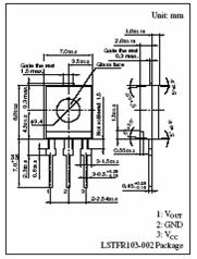
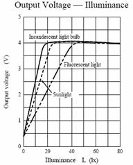
Figure 2-1: The PNA4603H Figure 2-2: Graph of the output voltage of the sensor
|
Voltage |
Bit Pattern |
Brightness Level of Room |
|
0V 1V |
Dark |
|
|
1V 2V |
Dim |
|
|
2V 3V |
Medium |
|
|
3V 4V |
Medium-High |
|
|
4V 5V |
Bright |
The clap sensor is intended to detect a sequence of claps and send a distinct signal to the PIC so that the latter can adjust the brightness of the light output accordingly; either brightening it, dimming it, switching it on, or switching if off. Assuming that the clapping switch will turn on and off with a single clap, the following rule was set in order to ease the construction of the rest of the circuit.
The initial design used a state machine to send inputs to the PIC. The way the state machine works is shown in Fig.2-3. The states are described in Table 2-2 and the action needed to be taken corresponding to the output is shown in Table 2-3. The outputs shown were to be taken as inputs to the microprocessor, which will then adjust the brightness of the lights accordingly.
|
Output |
Action |
|
On |
|
|
Off |
|
|
Bright |
|
|
Off |
|
|
Bright |
|
|
Dim |
 Figure
2-3: The state diagram
Figure
2-3: The state diagram
|
State |
1 Clap |
No Clap |
|
|
On |
Wait 1 |
On |
|
|
Wait 1 |
Wait 2 |
Off |
|
|
Wait 2 |
Dim |
Bright |
|
|
Off |
On |
Off |
|
|
Bright |
Wait 1 |
Bright |
|
|
Dim |
Wait 1 |
Dim |
Table 2-2: Description of states Table 2-3: Corresponding Action
This idea was abandoned because of the complexity to include other timing components with it. Also, it was realized that the clapping switch takes 2 successive claps to turn on and off. As such, a new design involving 2 counters and a timer was drawn up. The sound activated switch opens and closes due to waveforms detected by the microphone. Its operation is shown in Figure 2-4. This switch was to be connected to a circuit that counted the number of sets of claps heard (set of clap = 2 claps, with approximately 0.7 seconds in between claps). This circuit is shown in Figure 2-5, and it outputs a digital signal to the PIC for necessary action to be taken. Finally, the counters were to reset after approximately 7 seconds to get ready for the next instruction. This reset was to be controlled by the NE555 timer. The final design of the clap sensor is described in Section 3.
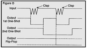
Figure 2-4: Operation of the sound activated switch

Figure 2-5: Circuit for counting the number of claps
Having received all the inputs from the light sensor, clap sensor, and buttons, the PIC is supposed to process these data and output the appropriate signals to the light output and the display unit. For PIC output to the lighting device, it was designed that a 3-bit signal be sent to a DAC which connects to the light output. The bit pattern as shown in Table 2-4 could be used to translate the following levels of brightness for the light bulb. The output of the DAC was then to be sent to the voltage source of the light, controlling the brightness of the light bulb.
|
Voltage |
Bit Pattern |
Brightness Level of Room |
|
0V 1V |
Dark |
|
|
1V 2V |
Dim |
|
|
2V 3V |
Medium |
|
|
3V 4V |
Medium-High |
|
|
4V 5V |
Bright |
Table 2-4: Bit pattern for output to the light bulb
Unfortunately, connecting the DAC directly to the output voltage of the light bulb was found to be undesirable; there was a need to isolate power and control. The final design implementation of how the PIC will control the brightness of the light bulb is described in Section 3.
3. DESIGN DETAILS
As mentioned, some of the initial designs as described above for various blocks of the project were deemed to be unsuitable or unfeasible. This section presents the final designs that were used in place of the initial ones and the updated schematics for each block, where necessary.
3.1 Detailed Description of Design
For the light sensor, instead of sending the output of the PNA4603H to an ADC, an analog data will be sent directly to the PIC. This component has been shown in Fig. 2-1. The PIC will convert this analog input into a digital signal.
The final design used for the clap sensor takes advantage of the nature of the output of the 1st one-shot. The way the 1st one-shot works in response to claps is shown in Fig. 3-1. Since there is a falling edge for each clap detected, a falling edge ripple counter is used to count the number of claps. A timer is used to reset the counter to zero after approximately 7 seconds, so that the device is ready for the next instruction. Because the timer output simultaneously resets the counter and triggers the PIC to read the input, latches are used to hold the value in the counter. The output from the latches then acts as input to the PIC. Also, since the output of the timer, connected to the reset of the counter, becomes high only when the 1st clap is detected, the counter is not able to count the 1st clap. Therefore, 1 is added to the value registered by the counter to account for the 1st clap. The final instructions are:
1. Circuit is closed (lights are on)
2. Circuit is opened (lights are off)
The circuit for counting the number of claps is shown in Fig. 3-2.


Figure 3-1: Operation of the entire circuit. Here, 2 claps are shown.
Figure 3-2: Circuit for counting number of claps
The main control of the system is done by the PIC. The program loops first check to see if an ADC conversion is necessary by checking a flag within the program. The flag is set by a timer interrupt that is set to go off every .8 milliseconds. This timer system prevents a constant flickering of the light input value when it is close to two discrete values. Then the program checks if the buttons or clap sensor have been triggered since the last loop. When the buttons or clap sensor are activated on port B, an interrupt is generated and the handler checks to see which button or clap sensor is actually triggered. Then a flag is set accordingly. The main program loop uses those flags to determine the next action and perform the appropriate calculations. Then using the sensor data and the user inputs through the button and the sound unit, an output level is calculated and an output duty cycle is determined from this output level. Finally, the preset level as determined by the user is displayed on the 7-segment display. The program repeats infinitely. Figure 3-3 shows the program control flow.
Figure 3-3: Program control flow of the PIC
The light sensor from Panasonic PNA4603H is intended detect the brightness level of the room. The detector will output an analog data to the PIC. This component is shown in Fig. 3 in Section 2. It outputs a voltage of approximately 0.5 V to 4 V depending on the luminance of the light source, as shown in Fig.4 of Section 2. PNA4603H will send the analog signal into the PIC, which will convert the input into a digital signal.
To power up the lamp, the PIC is connected to a MOSFET switch (MTP50N06V) which will control to turn the light on and off. The duty cycle in the PIC will control the different levels of brightness of the room. The MOSFET switch is connected to two power MOSFETs (IRF510) in parallel to each other which can output a current of 8A, which is enough current to power the lamp, which is 12V and 6A. The power MOSFETs are also connected to 2 heat sinkers to decrease the temperature of the MOSFETs when running the lamp.
To power up the lamp, the PIC is connected to a MOSFET switch (MTP50N06V). The MOSFET switch is connected to two parallel power MOSFETs (IRF510), which can output a current of 8A. This current is sufficient to power the lamp, which has specifications of 12V and 6A. The power MOSFETs are also connected to two heat-sinks to decrease their temperature when powering the lamp. One terminal of the light bulb is connected to the drain of the power MOSFETs in parallel while the other terminal is connected to 12 V. Figure 3-4 shows the schematic for the light output.

Fig. 3-4: Schematic of light output
3.2 Main Schematic

4. DESIGN VERIFICATION
Having the design of the project in mind and on paper, it was necessary to test if the design would work as intended. Much testing was done as the project was being assembled; components were tested, circuits were verified, and programs for the PIC were simulated. Once the parts have been assembled and interfaced, more testing was done to check the functionality of the product. This section presents the various testing methods that we used to check the workability of the design and to ensure the smooth execution of the end product.
4.1 Testing Procedure

 For the clap sensor, there were a number of components that needed to be
tested as stand alones before the implementation of the complete circuit. These
were the potentiometer, NE555 timer, ripple counter, and D latches. The outputs
that had to be tested were those coming from the 1st one-shot in the
clapping switch, NE555 timer, ripple counter, and D latches. Due to the nature
of the clap sensor, it was not feasible to simulate results in software such as
PSPICE. This is because some of the components are unique and cannot be found
in the software and also because the sound input cannot be generated there.
This led to testing of components individually after they have been set up by
means of an oscilloscope and a function generator. In particular, the timer was
tested extensively because some combinations of resistor and capacitor did not
work. As observed in Fig. 4-1, this was probably because the capacitor values
were too high and took too long to charge and discharge, contributing to the
breakdown of the timer function.
For the clap sensor, there were a number of components that needed to be
tested as stand alones before the implementation of the complete circuit. These
were the potentiometer, NE555 timer, ripple counter, and D latches. The outputs
that had to be tested were those coming from the 1st one-shot in the
clapping switch, NE555 timer, ripple counter, and D latches. Due to the nature
of the clap sensor, it was not feasible to simulate results in software such as
PSPICE. This is because some of the components are unique and cannot be found
in the software and also because the sound input cannot be generated there.
This led to testing of components individually after they have been set up by
means of an oscilloscope and a function generator. In particular, the timer was
tested extensively because some combinations of resistor and capacitor did not
work. As observed in Fig. 4-1, this was probably because the capacitor values
were too high and took too long to charge and discharge, contributing to the
breakdown of the timer function.
Figure 4-1: Testing of the timer
To test the light sensor part of the circuit, the PNA4603H was placed in environments of varying amounts of brightness and an oscilloscope was used to measure the output voltage. The light sensor was tested in a room with complete darkness, dim lights, and normal lighting, and also under a shadow, a flash light, and direct sunlight. The voltages read from the oscilloscope ranged from 0.5 V to 4.3 V. The results are shown in Fig. 4-2.
Figure 4-2: Response of PNA4603H under various lighting conditions
For simulation of codes written for the PIC, inputs were forced and the outputs that resulted were checked for accuracy. This was done by connecting a circuit on the breadboard and by using an oscilloscope to observe the appropriate outputs. Also, LEDs were connected to outputs of the PIC to see if the correct output is outputted on various pins. The 7-segment display connected to port D of the PIC was also helpful in determining if the internal calculations were correct.
4.2 Functional Testing
Once the design for each block has been assembled, the blocks were tested to check if they accurately accomplished their intended tasks. Then, blocks were interfaced and testing was done to verify that they interacted correctly and gave the right inputs and outputs.
For the clap sensor, 2 main aspects that needed to be tested are the sensitivity of the microphone to the clap of the user and the consistency of the output going to the PIC. The sensitivity of the microphone is controlled by the potentiometer on the circuit. To test the sensitivity of the microphone for each calibration of the potentiometer, a sound level meter could be used to measure the dB of each clap. One could then clap more and more softly until the switch does not respond to the noise anymore. Otherwise, a sound generator such as the JazBase03 could be used to generate the claps of certain loudness. However, these 2 equipments were not available at the time of testing and are costly equipment that cannot be purchased. In the end, it was deemed appropriate to inform the user of the range of the clap sensor with comfortable clapping. This is shown in Fig. 4-3.
|
Trim Pot Arrow Position |
Resistance (k-ohms) |
Range for comfortable clapping |
|
|
87 |
< 2 feet |
|
|
50 |
< 4 feet |
|
|
31 |
< 7 feet |
Figure 4-3: Range of clap sensor
The consistency of the output going to the PIC was tested by connecting LEDs to the D latches, where the output is to be taken, and the ripple counter. Then, clapping was done and the LEDs connected to the D latches were checked once the LEDs connected to the ripple counter were reset. This was done several times to ensure that the D latches gave consistent values that corresponded to the correct number of claps.
The light output was first tested by connecting one terminal to a 12V voltage source and the other to ground. The light became dimmer when we used a 5V source. Next, two power MOSFETs in parallel were tested by connecting the drains to one terminal of the light bulb, the sources to ground, and the gates to a 5V voltage source that acted as a PIC output. When all of the voltage sources were turned on, the light gave a dim output. When the 5V voltage source was switched to 12V, the light became brighter. This proves that the MOSFETs were turned on if the PIC outputs 12V, and off when PIC outputs 5V. However, when gate was connected to the PIC, the light could not turn on or off. Another MOSFET was then added to act as a switch for the PIC. The drain of this MOSFET was connected to a 12V voltage source through a 10K resistor, and the source was grounded through a 7.5K resistor. The drain was then connected to the power MOSFETs with a 100K resistor in parallel connected to ground. The voltage from the gate to drain was thus divided into two parts, and most of the voltage dropped across the 100K resistor to allow the light to turn on. Using the oscilloscope, the voltage output at the drain of the switch MOSFET at was found to be 12V when the gate was connected to a 5V voltage source. However, when voltage at the gate was close to zero, the voltage at the drain did not change. The light was not able to turn on. A possible reason was that the resistor at the source was dissipating too much current, therefore, the MOSFETs were tested by changing the value of the resistor at the source to ranging from 7.5K to 1K. The light was still not able to turn off. Finally it was realized that the resistor connected in parallel at the drain was too large; a single connection to the power MOSFETs would work better. After removing the resistor, the voltage output at the drain was zero when the gate was connected to zero voltage. This proved that the switch MOSFET worked as a switch to turn on and off the light. When connected to the PIC, the light was then able to be turned on and off according to the directions given by the PIC.
The PIC block was first tested running a simple program that would blink a single LED at a set period. This test allows us to confirm that the PIC can indeed be programmed and the I/O is working. Next, after the control program has been written, each module of the program was tested individually. The output to 7-segment display was tested first so we can use it to debug the rest of the program. It allowed us to display the values of operations and calculations performed by the PIC that otherwise would be invisible to the user. Right after, the internal ADC and the compiler built-in function was tested, by forcing input values and outputting to the 7-segment LED display to make sure they are correct. Figure 4-4 shows the data acquired. Then, the buttons were installed and the button interrupts were tested. When that was working, the light detecting sensors were installed and tested. The output level calculated from the preset level and the detected light level was then displayed on the LED display. Figure 4-5 shows the data acquired. Next, the PIC PWM (pulse width modulator) was implemented and tested. Using an oscilloscope, the duty cycle of the output of the PWM was recorded to verify the correct operation of this particular PIC function. The final product as a whole was tested by changing the level of brightness detected by the sensor and measuring the voltage produced by the light output. The results were then plotted on a graph with voltage of sensor vs. voltage of light output to determine the response of the system.
|
Input Voltage |
Displayed Value |
Expected Value |
Expected Level |
Fig. 4-4: Forcing inputs and checking 7-segment display
|
Preset Level 1 |
Preset Level 2 |
Preset Level 3 |
Preset Level 4 |
Preset Level 5 |
||
|
Darkness | ||||||
|
Dim | ||||||
|
Background lights | ||||||
|
Normal Room lights | ||||||
|
Direct Light |
Figure 4-5: Using light sensor and checking 7-segment display
5. COST
This section presents a list of parts used for each of the blocks and their cost. It also details the cost of labor involved from designing the project to building the end product.
5.1 Parts
Clap Sensor
|
Part |
Description |
Cost |
Number Used |
Total Cost |
|
276-150 |
Veroboard |
1.56 |
1 |
1.56 |
|
83-4000-000 |
15g Solder |
1.63 |
1 |
1.63 |
|
555 |
Timer |
0.55 |
1 |
0.55 |
|
MC74HC73N |
J-K F/F dual |
0.70 |
1 |
0.70 |
|
74AC11000 |
NAND dual |
1.60 |
2 |
3.20 |
|
1uF capacitor |
0.48 |
1 |
0.48 |
|
|
7.5M ohms 1/4W resistor |
0.12 |
1 |
0.12 |
|
|
0.01uF capacitor |
0.40 |
1 |
0.40 |
|
|
LED |
0.40 |
5 |
2.00 |
|
|
100ohms resistor |
0.12 |
2 |
0.24 |
|
|
100k-ohms resistor |
0.12 |
2 |
0.24 |
|
|
4.7k-ohms resistor |
0.12 |
1 |
0.12 |
|
|
10k-ohms resistor |
0.12 |
3 |
0.36 |
|
|
22k-ohms resistor |
0.12 |
1 |
0.12 |
|
|
100k-ohms resistor |
0.12 |
4 |
0.48 |
|
|
220k-ohms resistor |
0.12 |
4 |
0.48 |
|
|
330k-ohms resistor |
0.12 |
1 |
0.12 |
|
|
1M-ohms resistor |
0.12 |
1 |
0.12 |
|
|
4.7M-ohms resistor |
0.12 |
1 |
0.12 |
|
|
100k-ohms trim pot |
0.79 |
1 |
0.79 |
|
|
0.001uF capacitor |
0.35 |
4 |
1.40 |
|
|
0.01uF capacitor |
0.40 |
2 |
0.80 |
|
|
0.1uF capacitor |
0.29 |
2 |
0.58 |
|
|
1uF capacitor |
0.48 |
1 |
0.48 |
|
|
100uF capacitor |
1.60 |
1 |
1.60 |
|
|
2N3904 |
Transistor |
0.20 |
1 |
0.20 |
|
MPS6531 |
Transistor |
0.20 |
1 |
0.20 |
|
4001 |
IC |
0.35 |
1 |
0.35 |
|
4011 |
IC |
0.35 |
1 |
0.35 |
|
PC Board |
1 |
3.00 |
||
|
Microphone |
1 |
0.50 |
||
|
IC Socket 14-pin |
0.20 |
3 |
0.60 |
|
|
IC Socket 16-pin |
0.25 |
2 |
0.50 |
|
|
IC Socket 4-pin |
0.18 |
1 |
0.18 |
PIC
|
Part |
Description |
Cost |
Number Used |
Total Cost |
|
PIC16F877 |
Microcontroller |
9.50 |
1 |
9.50 |
|
4.7k-ohm resister |
0.12 |
3 |
0.36 |
|
|
Fox F1100E |
20MHz |
1.58 |
1 |
1.58 |
Light Sensor
|
Part |
Description |
Cost |
Number Used |
Total Cost |
|
PNA4603H |
Photodetector |
$3.61 |
3 |
$10.83 |
Light Output
|
Part |
Description |
Cost |
Number Used |
Total Cost |
|
Headlight |
12V lamp (Auto Zone) |
$7.40 |
1 |
$7.40 |
|
Headlight |
12V lamp (Wal-Mart) |
$6.14 |
1 |
$6.14 |
|
MTP50N06V |
Switch MOSFET |
$1.99 |
1 |
$1.99 |
|
IRF510 |
Power MOSFET |
$1.99 |
4 |
$8.00 |
|
T0-220 |
Heat-sinks |
$1.69 |
2 |
$3.40 |
|
Silicone Grease |
For Heat-sinks |
$1.99 |
1 |
$1.99 |
|
PK42 RH Screw |
To hold Heat-sinks and the power MOSFETs together |
$1.99 |
1 packet |
$1.99 |
Buttons
|
Part |
Description |
Cost |
Number Used |
Total Cost |
|
C&K 3531 |
Pushbutton |
1.20 |
3 |
3.60 |
Display Unit
|
Part |
Description |
Cost |
Number Used |
Total Cost |
|
LSD 3211-11 |
7-segment LED display |
0.90 |
1 |
0.90 |
|
470-ohm resistor |
0.12 |
2 |
0.24 |
Total Cost of Parts = $82.50
5.2 Labor
Lilly Wu: $50/hour
Jack Lai: $27.50/hour
Jane Chen: $35/hour
Total Cost of Labor: ($50 + $27.50 + $35)*2.5*140 hours = $39375
6. CONCLUSIONS
All the goals set out at the beginning of the term have been accomplished and the final demonstration achieved what was expected of the project. There are a few modifications that can be done to make this project even better. This chapter discusses the successes of the project, suggestions for existing problems, as well as recommendations for future project development.
6.1 Accomplishments
All the subprojects mentioned in Section 1 worked as they should. The light sensor, together with the PIC, was able to cause adjustments in the brightness of the lamp. The clap sensor was able to detect 1, 2, or 3 claps and after the preset 7 seconds send a signal to the PIC to read the number of claps recorded. The brightness of the lamp adjusted accordingly. Lastly, the lamp also reacted to button inputs and the current level of brightness of the lamp was displayed on the 7-segment display.
6.2 Uncertainties and Suggestions
The light output would sometimes flicker when the room was near darkness. After isolating the light output and the light sensor and performing tests, it was concluded that feedback from the light output to the sensor was the cause of this flickering. To solve this problem, two different solutions are proposed. Firstly, we can lower the frequency of the ADC reads. This way, small fluctuations in the environment would be masked and thus eliminating massive flicker. A more elegant solution would be to apply PID (Proportional, Integral, and Derivative) control to the light system. With the proper eigenvalues and coefficients, even small flicker could be eliminated very effectively.
6.3 Future Work
Instead of using a car headlamp, a florescent lamp or an ordinary lamp could be used for added practicality. Also, to enhance the aesthetic value of the project, the circuits could be soldered together on a PCB and then mounted in a case. Finally, a cost analysis could be done to determine the marketability of the product.
REFERENCES
Internet
R. Cantzler, PIC Programming HOWTO for ECE 345, May 2004, https://courses.ece.uiuc.edu/ece345/PIC/index.html
K. Lyons, Contextual Computating Group: PIC HOWTO, January 2000, https://www.gvu.gatech.edu/ccg/resources/pic/#5542
J. D. Chapman, PIC Tutorial, December 2002, https://www.users.globalnet. co.uk/~jchap/tvpropi.htm
J. E. Grover, Microprocessor Interfacing, December 2003, https://coel.ecgf. uakron.edu/grover/web/ee470
JoMoX GmbH, 2004, https://www.jomox.de/jazbase.html
Carles Electronics, Sound Activated Switch Kit, 2004, https://electronickits.com/kit/complete/elec/k-36.pdf
Panasonic, PNA4603H, 2003, https://www.semicon.panasonic.co.jp/ds/eng/SHE00045BED.pdf
Books
L. Sha, A/D D/A, class notes for CS 331, Department of Computer Science, University of Illinois at Urbana-Champaign, Spring 2004.
Microchip Technology Incorporated Technical Staff, PIC16F87X 28/40-Pin 8-bit CMOS FLASH Microcontrollers, Microchip Technology Inc., 1999.
Custom Computer Services Incorporated Technical Staff, C Compiler Reference Manual, Custom Computer Services Inc., July 2003.
|
Politica de confidentialitate | Termeni si conditii de utilizare |

Vizualizari: 2532
Importanta: ![]()
Termeni si conditii de utilizare | Contact
© SCRIGROUP 2026 . All rights reserved


