| CATEGORII DOCUMENTE |
| Bulgara | Ceha slovaca | Croata | Engleza | Estona | Finlandeza | Franceza |
| Germana | Italiana | Letona | Lituaniana | Maghiara | Olandeza | Poloneza |
| Sarba | Slovena | Spaniola | Suedeza | Turca | Ucraineana |
Piping & Instrumentation Diagrams Fundamentals
Detailed Steps
Step (3): Zone Creation Management
Step (4): Diagram Modification/Annotation/Reports
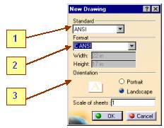
In this step you will learn how to start a new Piping and Instrumentation Diagram and how to set the proper options.
Once you have selected the P&ID workbench, a new drawing dialog box appears and you are prompted to select the following sheet options:
Standard
Format Type
Orientation
Change default options to desired specifications shown in the picture and click OK to activate Sheet 1.
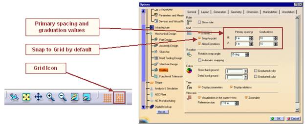
Setting your grid
3. Note: Use primary spacing and Graduations.
4.
Select Tools + Options - Mechanical
Design - Drafting, then click the General
tab and key in the primary spacing values and the graduations as shown in the
picture below.
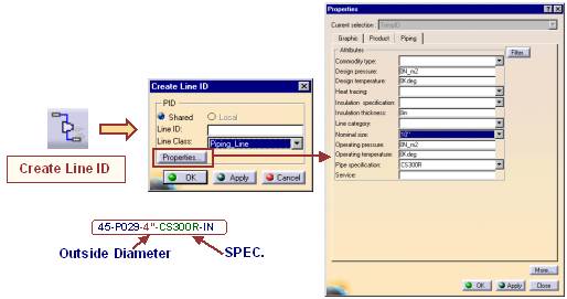
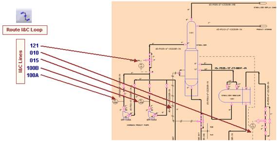
In this step you will learn how to create Logical Lines, place Equipment and how to route Lines between Equipment.
Note: The Specification and the Nominal Diameter for each line are depicted in the linenames.
Piping Lines
45-P029-4-CS300R-IN
45-P001-6-CS300R-IN
45-P002-4-CS300R-IN
45-P004-8-CS300R-IN
45-P005-10-CS300R-IN
45-P008-4-CS150R-IN
45-P009-4-CS150R-IN
45-P006-6-CS300R-IN
45-P010-2-CS300R-IN
I&C Lines
100A
100B
015
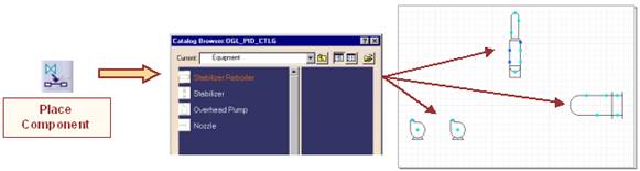
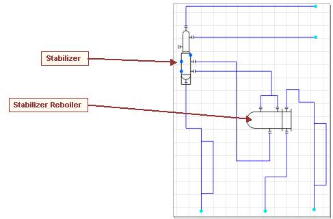
We will place the major equipment from the catalog. This is similar to the equipment
that was built
during
the setup training (Advanced Exercises).
Stabilizer
Stabilizer Reboiler
Overhead Product Pumps
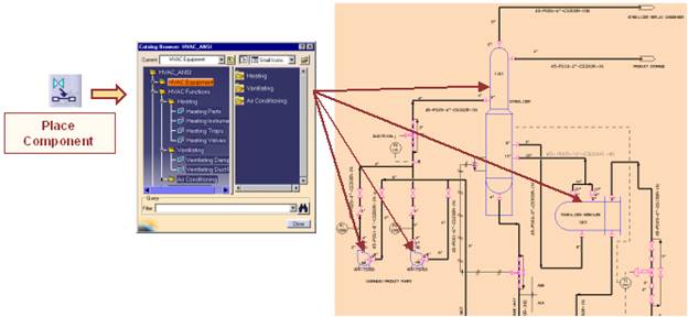
(refer to the setup training guide for the location of the catalog that was created).
Click the Place Component icon ![]() .
.
Select the Equipment from the catalog and place each part of the equipment as
shown
below
-> Stabilizer, Stabilizer Reboiler, Overhead Pumps.
Note: The color coded connectors that allows you to distinguish
between the piping connectors and
Instrumentation
connectors.
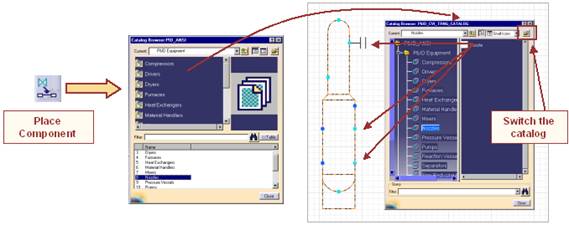
To place multiple symbols, double-click the Place Component button. Select the
button again
when
you are finished.
Select the catalog browser by clicking the Place Component button. Switch to the
default P&ID
Catalog
located in :
/intel_a/startup/EquipmentAndSystems/Piping/PipingDiagrams/
ComponentCatalogs/PID_ANSI.catalog
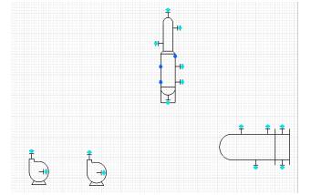
Select the Nozzle component and place the nozzles on the connectors.
Note: You only have to select the equipment and the compatible
connectors on the equipment
are
automatically detected for nozzle placement.
Place all the nozzles on the four pieces of
equipment.
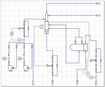
Your document containing the Equipment+Nozzles should appear as
shown
in the picture.
Using the Route Piping Line option ![]() ,
we will route the appropriate piping line (45-P029-4-
,
we will route the appropriate piping line (45-P029-4-
CS300R-IN)
by selecting the nozzle on the right overhead pump as the start point to the
nozzle
on
the stabilizer as the endpoint.
Next,
route from the left overhead pump and branch into the above line that was
routed.
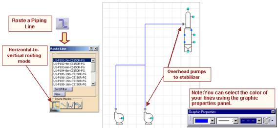
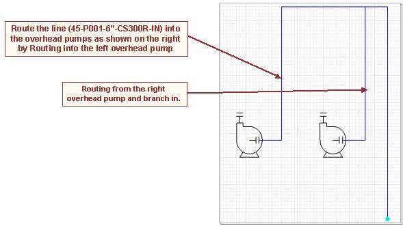
16. Route the Lines as shown in the picture below.
17.
After you have selected a Part from the Browser, move the cursor over the
appropriate position till
the Line
under the part turns red. Then
click to place the part.
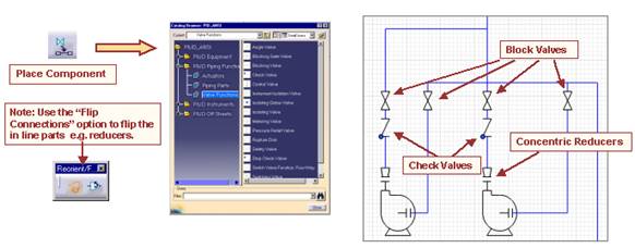
18. Place all the parts like it is done in the
diagram below.
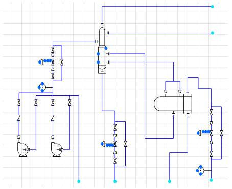
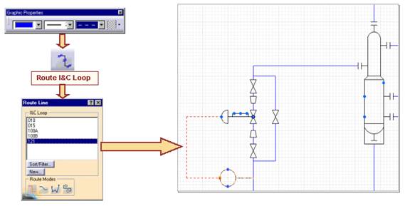
19. Using the Route I&C ![]() ,
route the following Instrumentation Lines.
,
route the following Instrumentation Lines.
20. Before you start routing you should adjust the graphical properties of the Line to create.
21. Then Click the Route I&C
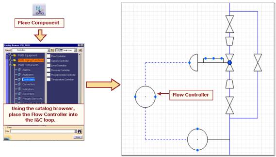
22. Place the Flow Controller as shown in the picture below.
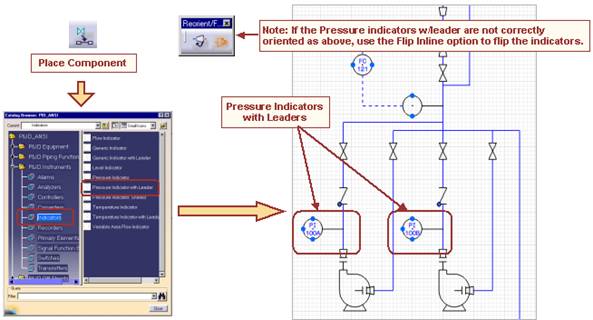
23. Place the two Pressure Indicators with Leader into the proper Instrumentation
Lines and flip
them
to the correct position using the flip
operation ![]() .
.
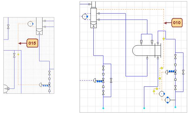
24. Use the techniques that you have explored in
the previous steps to complete the routing of the
I&C Loops 010 and 015.
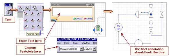
Using the create text icon, you can annotate your instrumentation bubbles
25. Select the Create text command ![]() .
.
26. Select the anchor point as bottom center ![]() .
.
27. Select the point on the bubble.
28. The Annotation
Editor panel is displayed. Key in the appropriate text (e.g. FC for Flow
Controller).
29. Click OK.
30.
Select your anchor point as top center ![]() ,
you can annotate the I&C
,
you can annotate the I&C
31. Start a new P&ID Document.
32. Route a P&ID Line.
33. Place an In-Line Blocking Valve.
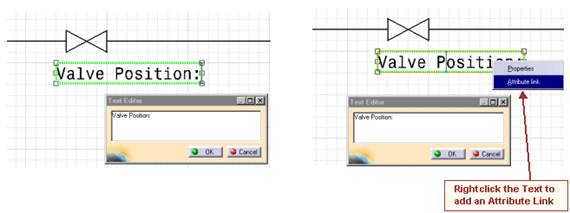
34. Using the Edit Properties option, switch the current valve position to Open.
35. Select the Create Text icon, key in Valve Position: as shown.
36. Right click on the Text and select the Attribute Link option.
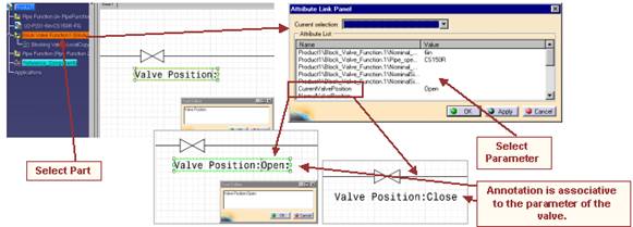
37. You are prompted to select the link. From the
tree select the Block Valve Function as shown
highlighted.
38. The Attribute Link Panel is displayed.
39. Select the Name: CurrentValvePosition.
40. Click OK in the AttributeLink Panel.
41. The Valve Position is annotated on the schematic.
42. Using the edit properties option, change the Valve Position to Closed.
43. In the command line, key c:force update. The
annotation is updated.
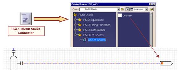
44. Click
on the Place On-Off Sheet Connectors
icon ![]() to place sheet connectors. The Catalog
to place sheet connectors. The Catalog
Browser
is invoked.
45. Select the On-Off Sheets catalog and then select the component: On-Off Sheet that is simply a
detail
that has been cataloged.
46. Place the sheet connector by selecting the connector/segment.
47. Note: The sheet connectors automatically place based on the flow.
48. Apply the Connectors
to the entire Diagram.
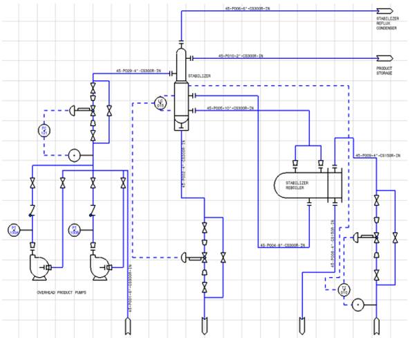
49. The final thing to do in this step is to annotate the diagram using the text
function till it matches
the picture on the next pages.
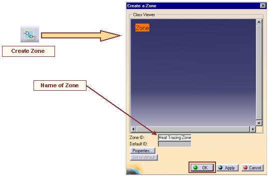
In this step you will learn how to create Zones and how to manage them.
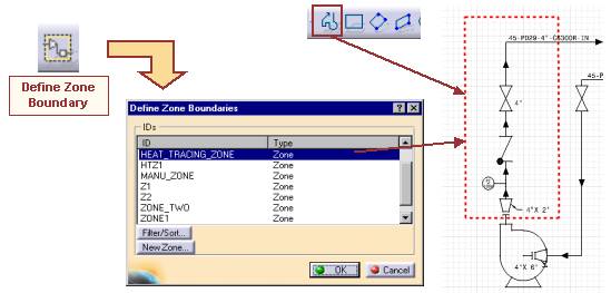
Select the Create Zone icon ![]() .
.
Key in a Zone ID e.g. HEAT TRACING ZONE
Select the OK button.
Create the Zone boundary geometry using V5R8 drafting tools (see next page).
Select the Define Zone Boundaries icon ![]() ,
the Define Zone Boundaries Panel is
displayed.
,
the Define Zone Boundaries Panel is
displayed.
Select the Zone ID.
Select the Boundary that you created in the previous step.
Select OK.
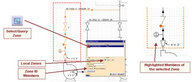
Select the Select/Query Zone icon ![]() ,
the panel is displayed.
,
the panel is displayed.
Select the Local option to display the local zones.
11. For the Selection Type option, select Zone ID Members.
Select the Zone ID and the members that belong to the highlighted zone.
Also, if you select a component that belongs
to a zone, the Zone ID, to which this component
belongs to, is highlighted.
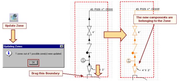
Drag the lower boundary so that the reducer and the nozzle are now part of the zone.
15. Select the Update Zone Icon ![]() ,
you will be prompted with the message 1
zones out of 1
,
you will be prompted with the message 1
zones out of 1
possible
zone(s) were updated.
16. Select OK.
17. Select the Select/Query Zone Icon, select the Zone ID, select the option Zone ID members.
18. The new components (the Reducer and the
Nozzle) now belong to the Zone.
In this step you will learn how to modify the positions of Lines and Equipment, how to modify Annotations, how to manage Flows and how to generate Reports.
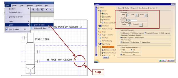
Gapping
operations are performed using the View option in the frame. Select Gaps Show All
Gaps.
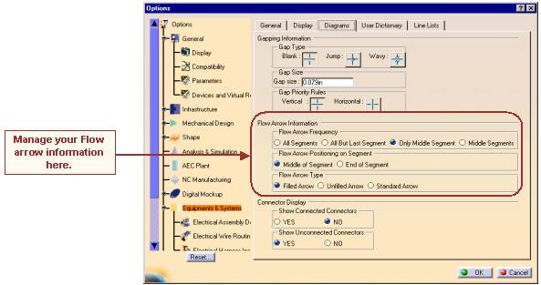
Gapping
management is performed using the Tools
- Options command. This option allows you
to
set parameters such as:
Gap Type
Gap Size
Gap Priority
3. Using the View - Flow option , you can Show or Noshow the flow for all lines.
You can use the Flow icons ![]()
![]() to show
the flow and to change your flow direction
for
to show
the flow and to change your flow direction
for
selected
lines.
An alternate method would be to use the contextual menu on the line segment.
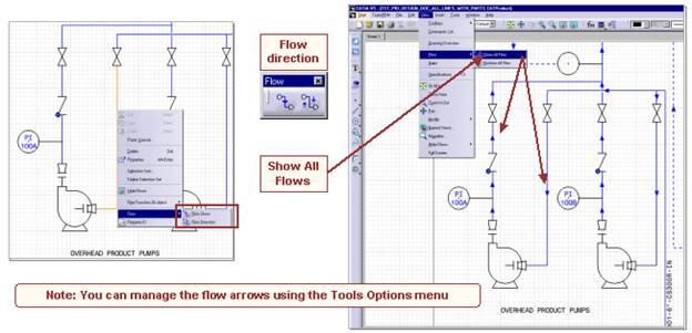
Using the Tools - Options Equipment&Systems - Diagrams tab, you can set
your Flow arrow
information:
Flow Frequency
Flow Positioning
Flow Arrow Type
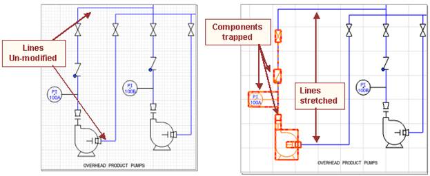
7. Stretch operations allow you to move components by trapping them.
E.g. selecting equipment with attached components will allow you to move it as an entity.
9. Trap a portion of your diagram and experiment with the stretch operations.
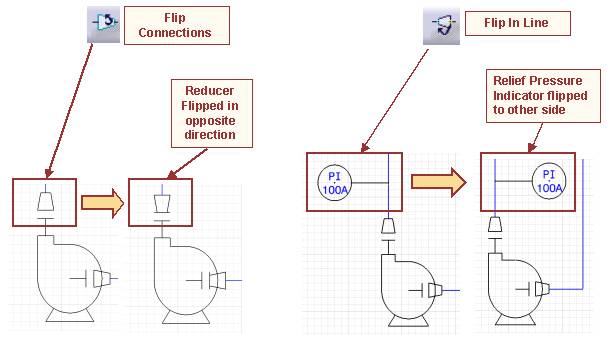
10. Flip Connections: Flips the Connectors of a Parts and reassembles it.
11. Flip In Line: Mirrors the Parts along the Line.
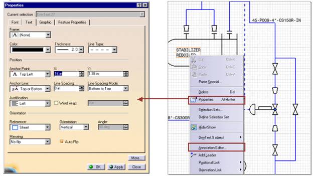
You can edit the properties on the annotation
using the Properties option by right
clicking on the
annotation.
To modify the annotation, use the Annotation Editor by right clicking on
the annotation.
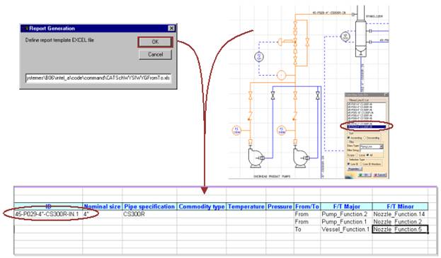
At first you need to select the Lines that
shall be included in the report. You can use the
Select/Query Line ID ![]() to select the desired Line Ids or just select
them in the tree.
to select the desired Line Ids or just select
them in the tree.
15. Then run the Report-Macro as shown below.
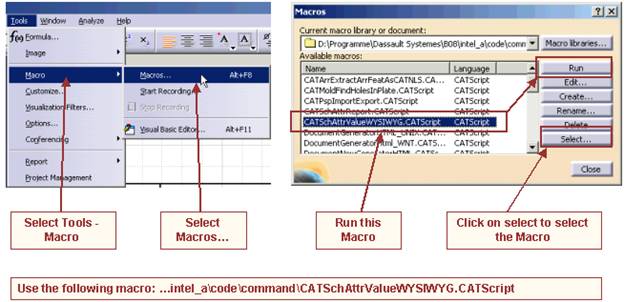
16. Confirm
the appearing dialog by clicking OK.
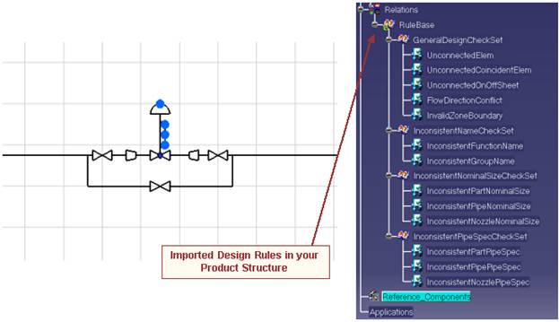
In this step you will learn how to implement and apply design checks to your piping diagram.
Design checks are executed via the Knowledge Expert workbench. Basically, rules are imported
into the design document and then executed against the components in the document.
Start a new P&ID Document.
3. Double click on the root product.
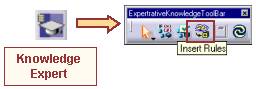
Using the Start menu, invoke the Knowledge Expert workbench.
Click on the Insert Rules Icon.
Select the document
PipingDiagramChecks.CATProduct from the following location:
intel_astartupEquipmentAndSystemsPipingDesignRules
7. Select the Open button.
The checks are imported into your design document.
In this scenario we will execute some of the checks.
9. Create a control station assembly as shown below.
10. We will explore the UnconnectedConcidentElem check by disconnecting one of the
components.
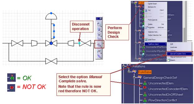
Disconnect one of the block valves so that the component is disconnected but it is still
coincident. Use the Disconnect
function ![]() .
.
Right click on the RuleBase and run the Manual Complete Solve from the contextual menu.
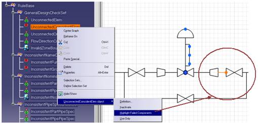
13. By
right clicking on the rule and using
the Highlight Failed Components
option from the
contextual menu, the failures can be displayed
interactively in the Tree Structure.
To generate a failure Report perform a right click on Rule Base and select RuleBase
object
Report.
15. Select the Directory where the Report shall be stored.
16. The Report will be generated in HTML format. To see the report, go to
the desired directory
and open the file main.html with a browser.
17. Every Item that is marked green is OK. Every red X marks a problem in your diagram.

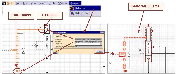
In this step you will learn how to use the network analysis function under Analyze Networks.
To perform a network analysis click on Analysis Network in the Menubar.
Activate the Network tab and select a part
from your diagram. Everything that
is connected to
the selected part will be
highlighted. In the Dialog the number of objects in network will be
displayed. When you click on Close the highlighted parts will be
selected.
Under the Path tab you can select two
objects (from to) in your diagram.
If there are more
than one possibilities to connect
the part, you might choose the desired path in the Current Path
selection box. In the Dialog the
number of objects in network will also be shown.
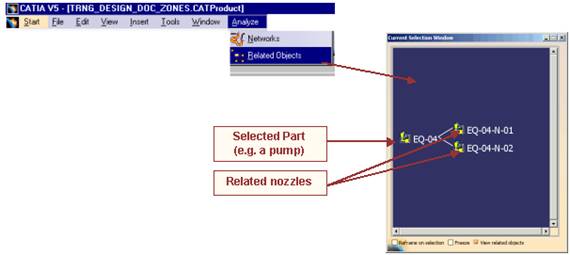
In this step you will learn how to use the object navigator.
The Object Navigator allows designers to browse their documents and view the objects for connectivity and also view the object properties.
Click on Analyze Related Object to start the Object Navigator.
Select a part from your diagram (e.g. a pump).
3. The Part and its related objects (e.g. a pump
and its nozzles) will be shown in the Current
Selection
Window.
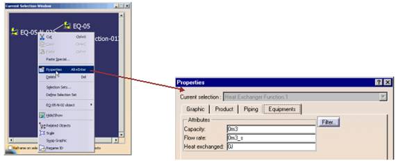
Using the object navigator
With a right
click you can enter the properties
menu of every part that is displayed in the Current
Selection
Window.
|
Politica de confidentialitate | Termeni si conditii de utilizare |

Vizualizari: 1413
Importanta: ![]()
Termeni si conditii de utilizare | Contact
© SCRIGROUP 2025 . All rights reserved