| CATEGORII DOCUMENTE |
| Arhitectura | Auto | Casa gradina | Constructii | Instalatii | Pomicultura | Silvicultura |
Plate and Shell Reinforcement
Robot Millennium allows for calculating of reinforcement areas for plates or shells. Plate and shell reinforcement type parameters depend on the selection of the code used during plate and shell design. A list of currently available plate and shell reinforcement codes includes:
American codes ACI 318/95 and ACI 318/95 (metric)
British code BS 8110
Eurocode 2 (with French, Belgian, Dutch, Italian, Finnish and German NADs)
Canadian code CSA A23.3-94
French codes BAEL91 and BAEL 91 mod.99
Dutch code NEN6720 (VBC 1995)
Spanish codes EH91, EHE98
Russian code SNiP 2.03.01-84
Polish code PN 84/B-03264 and Polish code PN-B-03264 (1999)
Romanian code STAS 10107/0-90
Norwegian code NS 3473E
Singaporean code CP65.
The option for definition of reinforcement parameters is available for only two types of structures (plates or shells) by:
selecting the command from the menu Geometry / Code Parameters / Reinforcement Type or
pressing
the ![]() icon.
icon.
The New reinforcement type dialog box is available by pressing the New icon on the Plate and Shell Reinforcement Type dialog box. The dialog box consists of three tabs: General, Materials and Reinforcement. The General and Reinforcement tabs are identical for all codes, whereas the shape of the Materials tab depends on the selected code of plate and shell reinforcement.
NOTE: In case of selecting some of the concrete codes, the Reinforcement parameters dialog box consists of four tabs, as additionally, it includes the SLS Parameters tab (it allows calculation of cracking and deflection for plate/shell structure).
On the General tab shown in the drawing below, the user should select additionally the type of calculations for shell structures; the following types of calculations are available
simple bending (plate)
bending + compression/ tension (shell)
compression or tension (membrane).
The Reinforcement calculations for shells option allows reduction of a set of internal forces that are considered while calculating panel reinforcement. Calculations may be performed for a complete set of forces (bending + compression/tension), only for bending moments (simple bending) or for membrane forces (compression/tension). Duration of calculations depends on the selected type of shell calculations. The option is available only for shells; when the Plate structure type is chosen, bending moments in a plate are considered in reinforcement calculations, whereas for the plane stress structure - membrane forces are taken into account
NOTE: The program does not verify if the settings adopted by the user are correct - improper use of the option may lead to wrong results.

In the lower part of the Reinforcement tab the following two options are provided:
Unidirectional reinforcement - if this option is switched on, then only reinforcement for the main direction will be calculated (forces acting in the perpendicular direction are ignored); it enables two-fold acceleration of calculations (take note that a simplification is adopted here, which is based on the negligible influence (or lack of influence at all) of forces acting in the perpendicular direction - on the main reinforcement; NOTE1: the program does not verify if the settings adopted by the user are correct - improper use of the option may lead to incorrect results; NOTE2: the codes for RC element design most often require that distributed reinforcement be provided for the direction perpendicular to the main reinforcement direction - the area of distributed reinforcement is not calculated in the program
Membrane reinforcement in one layer (in axis) - the option is accessible only if the compression/tension type is selected on the General tab; if this option is switched on, then reinforcement is positioned in axis of an RC element (reinforcement will be subjected to compression / tension due to membrane forces).
The table below shows the required parameters for the options: Unidirectional reinforcement and Membrane reinforcement in one layer (in axis) when they are switched on / off.
|
Reinforcement option |
Required parameters |
||||||
|
unidirectional |
in one layer (in axis) |
d1 |
d2 |
d1' |
d2' |
c1 |
c2 |
|
NO |
NO |
YES |
YES |
YES |
YES |
YES |
YES |
|
NO |
YES |
YES |
YES |
NO |
NO |
NO |
NO |
|
YES |
NO |
YES |
NO |
YES |
NO |
YES |
YES |
|
YES |
YES |
YES |
NO |
NO |
NO |
NO |
NO |
Same as in the dialog box used to define other structure attributes (supports, sections, etc.), the reinforcement type definition process has been divided into two stages:
reinforcement type definition
assigning reinforcement types to panels.
RC plate design can be started in two ways:
choosing from the vigniette of structure type selection (compare chapter 2.1) RC plate design - a plate design module will be working as a stand-alone program without connection (data exchange) with other parts of Robot Millennium system
once a structure is defined, one should select in it (by highlighting in a graphic editor) an appropriate panel (plate) list, and then choose the following command from the menu: Analysis / Design of RC Structure Elements / RC Plate and Shell Design / Required Reinforcement. It will result in running the RC PLATES - REQUIRED REINFORCEMENT layout and reading geometry, loads and obtained results into a code module. The screen will be divided into three parts: edit viewer with a designed plate view and two dialog boxes: Plate and Shell reinforcement and Reinforcement.
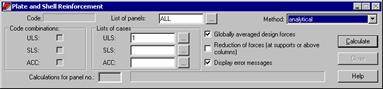
Description of RC plate design will be presented for a second case of calling a module of RC plate design. The option for calculating plate or shell reinforcement is available once the RC PLATES - REQUIRED REINFORCEMENT layout located in the RC Plates group is selected. A dialog box shown below appears at the bottom of the screen.
|
The upper part of the dialog box contains: name of the code used for determining reinforcement type parameters of a panel as well as the number of the version of plate and shell reinforcement module installed in the Robot system. To begin calculations of the plate or shell reinforcement, |
|
in the Case lists field - define the load cases taken into account during calculations for the individual limit states (ULS, SLS and ALS - accidental state). One should enter the numbers of load cases in the appropriate fields or press the (.) button and in the Selection dialog box one should select load cases or combinations of load cases for the individual limit states
in the List of panels field select panels that will be considered in calculations of the required reinforcement; the user should enter panel numbers (ALL denotes all the defined panels) or press the () button and choose panels in the Selection dialog box
if code combinations were previously created then activating an appropriate option in the Code Combinations field ( symbol appears) determines the limit state, for which the generated code combinations will be included in calculations
determine the method of calculating shell or plate reinforcement; the following calculation methods are available in the program: analytical method, the method of equivalent moments (NEN) and Wood&Armer method of equivalent moments.
NOTE: Panel calculations are performed only for the panels whose numbers have been entered in the List of panels edit field and for the cases or case combinations specified in the ULS, SLS, ACC edit fields.
NOTE: After modifying parameters of a reinforcement set ascribed to a panel for which the necessary reinforcement has been calculated or after changing a reinforcement parameter set for a panel, the status of reinforcement calculation results changes to out-of-date for such a panel. The reinforcement calculation results are removed, whereas in the reinforcement result table, the table cells are presented in red (maps of reinforcement and panel cuts are inaccessible) for such a panel.
In Robot the width of cracking is calculated independently for two directions defined by axes of reinforcement. This is an approach analogous to the simplified methods presented in relevant literature. The implementation of the method not related to codes results from lack of relevant recommendations concerning plates with cross reinforcement.
The algorithm of calculations is based on the formulas enabling calculation of cracking width for beam elements. Calculations are carried out on the cross-section with reinforcement resulting from Ultimate Limit State for all the forces caused by the loads defined as SLS or appropriate SLS combination. The moments recognized in calculations of Serviceability Limit State are equivalent moments calculated according to the selected calculation method: analytical, NEN or Wood&Armer. The analytical method for Serviceability Limit State does not recognize actions of mxy moments. Thanks to the implementation of NEN or Wood&Armer method, one may recognize the mxy moments in calculations by increasing the moments mxx and myy. Wood&Armer method is recommended for calculations of plates with cross reinforcement among others by ENV 1992-1-1 EUROCODE 2 (Annex A.2.7).
The calculated cracking width whose value is presented in the table of results is the maximum value obtained from all the analyzed load cases.
The algorithm for calculating deflections of RC plates is based on the use of calculations of an isotropic elastic plate, with the stiffness of the cracked element recognized. Originally, the deflections are obtained from the calculations performed according to the finite element method (FEM). Then, they are modified. Deflections may be identified with displacements only for not deformed supports. In the shell module (3D) while calculating RC plate deflection, the displacement of the least displaced support is subtracted from displacements of each element. It means that the deflections are measured from the plane parallel to the not deformed plate surface that passes through one support point of the deformed plate.
One should pay attention to displacements of the remaining supported corners of a plate.
The calculation algorithm used in the Robot program is based on the assumption that it is possible to obtain an RC plate deflection by means of multiplying its elastic deflection by the coefficient defining stiffness change.
![]()
where:
ub - displacement of an RC plate
u - elastic displacement of a plate
D - elastic stiffness of a plate
B - equivalent stiffness of an RC plate.
Once the
FEM calculations and the calculations of reinforcement resulting from
Afterwards, the average stiffness of elements is calculated. The assumption that the plate stiffness equals average stiffness of elements causes the calculated deflections to be smaller than real ones.
The next calculation step is to find an element with the least stiffness. If the plate stiffness identical to this element stiffness is adopted for calculations, the deflections will be overrated.
Since the searched value lies between thus calculated values, the following may be adopted:
![]()
The alpha coefficient has been determined on the basis of data concerning deflections of typical RC plates and equals 0.25.
If the Reinforcement adjustment option is switched on, the program increases the reinforcement area during calculations to increase the stiffness of the element, which, in consequence, leads to reduction of deflections. In both directions the reinforcement is distributed in inverse proportion with respect to stiffness. In the case when it is not possible to fulfill the condition of maximum deflection defined by the user, the table of results will display appropriate warning (red background of the result cell). The program does not have any limits set on reinforcement ratio (other than the code-defined ones), so one should pay attention to the economic aspect of the solution provided.
The central part of the dialog box contains the Globally averaged design forces option. It appears in this dialog box for the results of calculations of plates and shells are discontinuous for the forces in nodes of finite element mesh (if four finite elements converge in one node, a different force value is determined for each element). If the Globally averaged design forces option is switched off, the results in nodes are averaged within a given panel for which reinforcement is being calculated. If the option is switched on the results in nodes are averaged for all panels.
NOTE: If the Globally averaged design forces option is switched on, one should be careful while calculating reinforcement for plate structures consisting of panels that are not located in one plane, for global averaging may result in the situation where quantities that do not correspond to each other are averaged for edges of such panels.
Two options are located in the in the bottom part of the dialog box:
display error messages - if this option is active, possible reinforcement calculation error warnings will appear on the screen during reinforcement calculations.
reduction of forces (at supports or above columns)
For plate and shell elements supported at points (by means of the available support types or columns), values of moments and stresses near the support points may be considerably greater than at the remaining points of the plate. It may cause calculation of incorrect reinforcement in the vicinity of supports and columns; to avoid that, such connections may be modeled by means of the rigid links available in the program or by applying the Reduction near supports option.
Reduction of values near supports consists in replacing the result values obtained in the vicinity of supports and columns with the average value obtained in the neighborhood of these supports. Three stages may be distinguished in the option operation:
definition of support nodes - the program reduces values only near the nodes considered as "supported"; these are the nodes at which:
a column type support (rectangular or round) is defined with non-zero dimensions - advanced parameters for supports
bar elements are connected with finite elements (but only when the other bar end is not connected with the same finite element, either - as it is the case for a strengthening beam); moreover, for a node to be considered as supported, it must be adjoined by at least one finite element
At nodes where supports at points (without dimensions) and beam (linear) supports are defined, values are not reduced.
definition of a reduction radius - if reduction of selected values is performed at a given node, then it should be determined which values should be disregarded; the values ignored include the values at this node and at centers of elements that adjoin this node; apart from that, the program looks for nodes positioned in the distance lesser than the reduction radius - values at these nodes will also be disregarded and replaced with the calculated average value; the reduction radius is determined in the following manner:
for a support defined at a node - the reduction radius equals half the length of the diagonal of a rectangular support or half a diameter of a round support
for a column adjoining a node - the reduction radius equals half the length of the diagonal of a rectangle with dimensions equaling the column width and height.
If one node is adjoined by several "supports" with different values of reduction radiuses, then the greatest of the calculated radiuses is adopted in calculations.
calculation of the average value - once the reduction radius value is calculated, the program searches nodes positioned in the distance (from the supported node) lesser than the determined radius value; the result values in all these nodes and in centers of finite elements that adjoin them are disregarded; these values are replaced with the average of the result values on the edge of the disregarded region - when calculating this average the averaging parameters are taken into account; if a node is adjoined by an element, in case of which at least one of the nodes is positioned inside the "reduction circle", then a value from this element is also ignored while averaging.
Once the averaged value is calculated, it substitutes for all the values disregarded in the vicinity of a given support node.
The following can be selected in the Reinforcement dialog box that is located in the right part of the RC PLATES - REQUIRED REINFORCEMENT layout:
calculated reinforcement areas and spacing: Top Ax, Bottom Ax, Top Ay, Bottom Ay, Top sx, Bottom sx, Top sy, Bottom sy and Transversal At.
Theoretical (required) areas of reinforcement obtained during the design of a plate/shell structure may also be presented in the form of reinforcement crosses. The crosses of the reinforcement area or the spacing of the reinforcement will be presented if one selects the On option.
In case of concrete code selection which allows calculations considering service limit state, there is additional tab: SLS accessible in the Reinforcement dialog box. One can select the following quantities to be presented on this tab (depending on a code - not all quantities are available): cracking width in both directions (ax and ay), deflection f.
Once calculations of theoretical (required) reinforcement are performed one can shift to the RC PLATES - PROVIDED REINFRCEMENT layout. The options available in the Results dialog box allow presentation of the results of reinforcement area calculations: a presentation of real (provided) reinforcement zones and a manual modification of these results. The Results dialog box consists of two tabs: Bending and Punching.
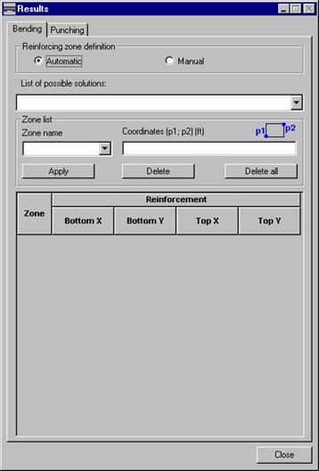
The dialog box shown in the figure above consists of three main parts:
reinforcement zone definition: automatic / manual (working mode definition)
selection of lists of solutions
presentation fields of real (provided) reinforcement for a selected solution.
Definition of reinforcement zones
The program allows to determine real (provided) reinforcement zones in two modes: automatic and manual.
The automatic mode allows to generate reinforcement zones and calculate a real (provided) reinforcement area on the basis of the accepted reinforcement parameters, calculation options and on the basis of the calculated earlier theoretical (required) reinforcement areas. Reinforcement zones are determined by the optimizing algorithms. When the calculations are completed, a user can select a solution from a list of the available solutions proposed in a program.
To optimize reinforcement zones a solution taking into consideration several factors should be found. For wire fabric reinforcement the optimization aims are as follows:
cut number to achieve the appropriate cuts
mass of reinforcing wire fabrics
usage ratio for wire fabrics.
For a bar reinforcement a spacing modularity, an assortment decrease of the used bars or a used steel mass is preferred.
A manual mode allows a user to define real (provided) reinforcement zones. In this case the program only selects the appropriate reinforcing bars and wire fabrics (on the basis of the calculated theoretical (required) areas, reinforcement parameters and calculation options).
After selecting the Manual option of a zone definition and moving to a graphical viewer, a mouse cursor changes its shape (to a cross shape), that allows to insert the zones.
A definition method of reinforcement zones is similar to a definition of rectangular contours. The definition consists in determination of two points position. The first click with a left mouse button results in the first corner definition and moving to a rectangle dragging mode. Clicking again results in a opposite corner definition. When the zone geometry is defined, a zone name should be given and press the Apply button.
The Delete button results in deleting the current selected zone from a list, while the Delete All button results in deleting all zones from a list.
Solution list
A solution list allows to select one of several, possible solutions, proposed by the program. The solutions are sorted out according to an optimization coefficient. This coefficient is the weighted average of the parameters being the optimization aim. It should be taken into consideration that the solutions making reinforcing works easy are preferred more to these requiring less steel amount.
When wire fabric reinforcement option is selected, the solution list includes: a number and type of used wire fabrics, percent of wire fabric consumption and a total mass of wire fabrics with wastes.
For the bar reinforcement the following items are given on the solution list: estimate survey for the weight of all bar types and survey for total steel weight. In these results the mass being a result of the demanded bar laps and a structural reinforcement.
Presentation and modification of reinforcement zones
The fields located in the Zone list table facilitating a presentation and modification of reinforcement zones. For a selected zone, the coordinates of the left bottom and right top zone corner are determined.
The selected zone is highlighted in the table presenting the reinforcement values and in the viewers presenting the top and bottom reinforcement zones. The active zone can be modified by a user.
NOTE: Any zone modification during the operation in the automatic mode results in moving to the manual node.
The options located on the Punching tab allow to:
view and define the punching verification points
group the verification points (unify the geometry)
assign the supports (columns) the geometrical properties of the head
view the punching calculation results.
Viewing and adding the defined by the user verification point
If in a structure the point supports are defined, they are automatically entered on the point list and denoted by the letter S with consecutive ordinal numbers. For each support type the following things can be read:
coordinates in the Position field
number on the node to which a support is assigned (in the Node number field)
maximum reaction value of a support in the Maximum punching force field
support geometry if such one is defined during the support definition in the Advanced dialog box.
To display data concerning a selected verification point, one should only select its name located on the point list.
Independently from supports, verification points can be defined by the user.
To define a new verification point, one should press the New button in the Verification points field. Each time when the operation is completed, the verification point denoted by letter P and the consecutive ordinal number is added to the point list. Once a verification point is chosen the fields allowing definition of the point position, load geometry and values of punching force are active. These values are saved (no additional operation to confirm them is needed).
To delete the added verification point, one should select it and press the Delete button. The points, which are the supports defined in a structure geometry (denoted by the letter S) cannot be deleted.
Support (column) heads
The program allows to define heads over the supports (columns), that are taken into consideration in the punching calculations. To perform it, the Head option should be active (the fields with the dimensions are available) and the head values should be defined. For the head on the rectangular support they are the lengths of the head sides on the level where head meets the slab (denoted by the letters a and b) and the head height denoted by the letter h. For the heads over the circular supports it is the d head diameter and h head height (for a circular head) or the lengths of the head sides (denoted by the letters a and b) - for a rectangular head.
When the support belongs to a group, the head is applied to all elements of this group.
Point grouping
Both, the additional verification points and supports can be grouped to modify the geometry in the easier way. The points may be grouped manually by selecting on the name list and pressing the > button; it is also possible to group all the supports automatically: one should press the >> button.
The additional verification points can be grouped if they have the same geometry type. In a case of supports, a compatibility of the support dimensions is necessary. If the conditions to a compatibility of the support dimensions are not satisfied, the verification points or supports not compatible with the first one on the list are deleted in a moment of the group confirmation.
When the points with different dimensions are grouped, the dimension values are accepted on the basis of the first defined point in the group. When a new point is added to the group, its dimensions are automatically changed to the compatible ones with the group dimensions. Grouping the supports with different head dimensions is done by analogy.
When the group is defined, any change for the arbitrary group component relates to the entire group and it is modified.
Presentation of calculation results
In the table presenting the results of the punching analysis for each verification point the following values are presented:
admissible punching force calculated by the program according to the appropriate code requirements
generalized design force defined in the Maximum punching force field for the additional verification points or read from FEM calculation results for supports
critical circumference calculated on the basis of code requirements
reinforcement, which includes:
reinforcement range from the member center in both perpendicular directions L1 and L2
circumference of reinforcement zone (if required)
total area of reinforcement
number and diameter of bars calculated on the basis of the total area and settings in the options for punching
safety factor being a ratio of a maximum punching force and admissible punching force.
Punching analysis results for individual points are presented in the color corresponding to the calculation result:
in blue - for points that fulfill the conditions for punching and do not require reinforcement
in green - for points that fulfill the conditions for punching and require reinforcement
in red - for points that do not fulfill the conditions for punching despite applying reinforcement.
The critical circumference is presented graphically on the Slab - reinforcement layout as a green line around columns. The range of punching reinforcement is shown graphically in a final drawing of a slab (formwork).
The Punching tab may include additional options; it depends on the selected code of RC structure design.
ACI Code
Once this code is selected, in the above dialog box the Type option is also available which for each support determines its position: within slab, on slab edge or in slab corner. The support type is used during calculation of the admissible punching force [ACI 318-99 11.12.2.2].
EC2 Code
Once this code is selected, in the above dialog box the b option is also available. For each support the parameter determines position of the support: within slab, on slab edge or in slab corner. A value of this parameter is used during calculation of the punching force [ENV 1992-1-1 EC2 4.3.4.3].
Once real (provided) reinforcement calculations for a plate are completed one can present calculation results in the form of a calculation note (the Results / Calculation note option). The program will display the text editor of the Robot Millennium system containing designed plate data and obtained calculation and design results.
Once the Results / Drawings option is selected
from the menu or the ![]() icon is pressed the Robot program will
activate the FINAL DRAWINGS layout
which will present a final drawing of a calculated and designed plate. The
shape of the final drawing of a plate presented on the screen corresponds to
the accepted drawing parameters (see chapter 6.2.5).
icon is pressed the Robot program will
activate the FINAL DRAWINGS layout
which will present a final drawing of a calculated and designed plate. The
shape of the final drawing of a plate presented on the screen corresponds to
the accepted drawing parameters (see chapter 6.2.5).
The analytical method of calculating plate and shell reinforcement area implemented in Robot is based on the conception presented in the A.Capra and J-F. Maury's article titled "Calcul automatique du ferrailage optimal des plaques et coques en beton arme", Annales de l'Institut Technique du Batiment et des Travaux Publics, No.367, Decembre 1978.
Calculations procedure
The calculations procedure is based on the fundamental assumption that, if the reinforcement values Ax and Ay - corresponding to two perpendicular directions 'x' and 'y' - are given, one may adopt a "equivalent" reinforcement in any other 'n' direction, calculated from the following formula:
![]()
where: ![]()
The values of sectional forces (moments and membrane forces) Mn, Nn may be obtained from the following transformational formulas:
![]()
Thus, the below-presented inequality formulates the condition of 'correct' reinforcement, i.e. the reinforcement that is able to carry the internal forces in an arbitrary section:
![]()
where the function F(Mn, Nn) refers to the value of reinforcement required to carry the forces calculated for the direction 'n' - Mn, Nn.
Inequality ![]()
determines on the plane (Ax, Ay) the area of "admissible" values of reinforcement Ax, Ay (half-plane). If such area is determined for a sufficiently "dense" set of directions 'n' (the program assumes that control is performed every 10 ), one obtains the area of admissible values Ax, Ay.
The reinforcement adopted by the program is the minimal reinforcement (it yields the minimal sum of surfaces Ax+Ay).
If a structure type or selection of calculation options causes reduction of internal forces, the reinforcement is calculated based on the following:
Mn moments - plate structure or simple bending option in a shell structure
Nn membrane forces - plane stress structure or compression/ tension option in a shell structure
complete set of Mn, Nn forces - bending + compression/ tension option in a shell structure.
Please take note that in calculations of unidirectional reinforcement, the analytical method is limited to calculating the reinforcement only for the main reinforcement direction, without dividing it into 'n' directions. It means that a plate is designed only for Mxx and Nxx set of forces.
The program Robot Millennium provides also the possibility of using the method of determining equivalent moments devised by Wood and Armer (supplement to the European code [ENV 1992-1-1 EC2 Design of Concrete Structures - Appendix 2, point A.2.8 Reinforcement in Slabs]).. The detailed description of the method may be found, for instance, in R.H. Wood - "The reinforcement of slabs in accordance with a pre-determined field of moments", Concrete, February 1968, August 1968 (correspondence).
Calculation procedure
When calculating reinforcement of a plate structure or activating the option of panel design for simple bending in a shell structure, design moments are calculated according to the method by Wood and Armer (formulas are given below).
For a selected direction 'x' (and the corresponding perpendicular direction 'y') one calculates two types of design moments M*: the 'lower' ones (positive, causing mainly tension in the bottom parts) and the 'upper' ones (negative, causing tension in the upper parts). The general procedure takes the following form:
Determination of the 'lower' moments Mxd*, Myd*:
Mxd* = Mx + |Mxy|
Myd* = My + |Mxy|
However, if Mx < -|Mxy| (i.e. the calculated Mxd* < 0)
Mxd* = 0
Myd* = My + |Mxy2/Mx|.
Similarly, when My < -|Mxy| (i.e. the calculated Myd* < 0) (*)
Mxd* = Mx + |Mxy2/My| (*)
Myd* = 0 (*)
If any of thus obtained moments Mxd*, Myd* is smaller than zero, one should assume the zero value (the design moments for tension in the upper layers are determined further on in the text).
Determination of the 'upper' moments Mxg*, Myg*:
Mxg* = Mx - |Mxy|
Myg* = My - |Mxy|
If Mx > |Mxy| (i.e. the calculated Mxg* > 0) (*)
Mxg* = 0 (*)
Myg* = My - |Mxy2/Mx| (*)
Similarly, when My > |Mxy| (i.e. the calculated Myg* > 0)
Mxg* = Mx - |Mxy2/My|
Myg* = 0.
If any of thus obtained moments Mxg*, Myg* is bigger than zero, one should assume the zero value (such moments would design the lower reinforcements, which is already guaranteed by the formerly calculated 'lower' moments Mxd*, Myd*)
Analogously, design forces are calculated from the formulas given below for a plane stress structure or for the activated option of panel design for compression/ tension in a shell structure.
For the selected direction 'x' (and the corresponding perpendicular direction 'y') one calculates two types of design forces N*: the 'tensile' ones (positive, causing main tension in a section) and the 'compressive' ones (negative, causing section compression). The general procedure takes the following form
Calculation of 'tensile' forces Nxr*, Nyr*:
Nxr* = Nx + |Nxy|
Nyr* = Ny + |Nxy|
However if Nx < -|Nxy| (i.e. calculated Nxd* < 0)
Nxr* = 0
Nyr* = Ny + |Nxy*Nxy/Nx|.
Similarly, if Ny < -|Nxy| (i.e. calculated Nyr* < 0) (*)
Nxr* = Nx + |Nxy*Nxy/Ny| (*)
Nyr* = 0 (*)
If any of thus obtained forces Nxd*, Nyd* is less than zero, one should assume the zero value (forces designing a section by reinforcement compression are determined further on).
Calculation of 'compressive' forces Nxs*, Nys*:
Nxs* = Nx - |Nxy|
Nys* = Ny - |Nxy|
If Nx > |Nxy| (i.e. calculated Nxs* > 0) (*)
Nxs* = 0 (*)
Nys* = Ny - |Nxy*Nxy/Nx| (*)
Similarly, if Ny > |Nxy| (i.e. calculated Nys* > 0)
Nxs* = Nx - |Nxy*Nxy/Ny|
Nys* = 0.
If any of thus obtained forces Nxs*, Nys* is greater than zero, one should assume the zero value (such forces design a section by reinforcement tension, which is already guaranteed by the 'tensile' forces Nxr*, Nyr* calculated earlier).
NEN Method
The method of design for the given equivalent moments is adopted in the Dutch code NEN 6720 (section 7.3.2).
Calculation procedure
The following algorithm is a simplification of Wood and Armer algorithm.
When calculating reinforcement of a plate structure or activating the option of panel design for simple bending in a shell structure, design moments are calculated according to the NEN code (formulas are given below).
Determination of the 'lower' moments Mxd*, Myd*:
Mxd* = Mx + |Mxy|
Myd* = My + |Mxy|
Determination of the 'upper' moments Mxg*, Myg*:
Mxg* = Mx - |Mxy|
Myg* = My - |Mxy|
Analogously, design forces are calculated from the formulas given below for a plane stress structure or for the activated option of panel design for compression/ tension in a shell structure.
Calculation of 'tensile' forces Nxr*, Nyr*:
Nxr* = Nx + |Nxy|
Nyr* = Ny + |Nxy|
Calculation of 'compressive' forces Nxs*, Nys*:
Nxs* = Nx - |Nxy|
Nys* = Ny - |Nxy|
For the complex stresses (shells with the activated option of panel design for bending + compression/ tension), with bending moments (Mxx, Mxy, Myy) and membrane forces (Nxx Nxy, Nyy) acting simultaneously, there is no simplified algorithm devised. Since it is often the case that the modeled shells work almost as plates (with slight membrane forces acting), therefore the possibility to calculate moments Mxd*, Myd* according to the method presented still remains and these design moments are superimposed with longitudinal forces Nxx, Nyy.
Complex stresses
Simplified methods used in the Robot program enable speed-up of calculations if 'pure' flexural state (plates, simple bending) or membrane state (plane stress structure, compression/ tension) occurs. There is no ready simplified algorithm for a complex state (shells) which implies additional membrane forces (Nx Nxy, Ny). It seems that the implementation of the 'analytical' approach is the only admissible procedure.
However, as the modeled shells frequently work as plates (when the membrane forces are negligible), the program still provides the possibility of selecting a simplified method of calculating design moments on which the longitudinal forces Nx, Ny are superimposed.
It should be stressed that this solution is justified only for relatively small membrane forces and it is the user who takes the responsibility for a particular case of implementing this procedure.
Comparison between methods
In the performed tests, the differences between the results obtained by calculating reinforcement by means of the analytical method and the simplified ones have not exceeded 5% of reinforcement area (the simplified methods yielded a slightly greater maximum reinforcement).
The analytical method is the most complicated, as regards the computational procedure, of the methods of reinforcement calculation in the Robot program. Duration of calculations by means of the analytical method (except calculations of plates with unidirectional reinforcement) may considerably grow (depending on a structure, the duration grows from 100% to 500%) as compared to Wood&Armer or NEN methods.
|
Politica de confidentialitate | Termeni si conditii de utilizare |

Vizualizari: 3543
Importanta: ![]()
Termeni si conditii de utilizare | Contact
© SCRIGROUP 2026 . All rights reserved