| CATEGORII DOCUMENTE |
| Bulgara | Ceha slovaca | Croata | Engleza | Estona | Finlandeza | Franceza |
| Germana | Italiana | Letona | Lituaniana | Maghiara | Olandeza | Poloneza |
| Sarba | Slovena | Spaniola | Suedeza | Turca | Ucraineana |
The definitions of the beam and cross-section were specified in the previous lectures. Some geometrical characteristics of the cross-section, such as the area and moments of inertia, have a central role in the theoretical development of Mechanics of Materials and are the main subject of this lecture.
Definitions
The beam cross-section is a plane area bounded by a closed curve ![]() . For mathematical convenience the Cartesian plane coordinate
system
. For mathematical convenience the Cartesian plane coordinate
system ![]() , as illustrated in Figure 1, is defined.
, as illustrated in Figure 1, is defined.
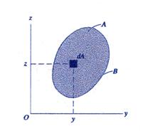
Figure 1 Cross-Section Area
The total area of the cross-section is calculated as:
![]() (1)
(1)
The integral contained in equation
(1) defines the summation of the differential areas![]() over the two defining variables
over the two defining variables ![]() and
and![]() . The area is characterized by units of length squared [L2],
with the symbol [L] representing length.
. The area is characterized by units of length squared [L2],
with the symbol [L] representing length.
The first moments of the area ![]() about the coordinate
system axes
about the coordinate
system axes ![]() and
and ![]() are called the static
moments. These are defined as:
are called the static
moments. These are defined as:
![]() (2)
(2)
![]() (3)
(3)
The units of the static moments are [L3].
The geometric center of the
cross-section is called the centroid.
Equations (4) and (5) are used to calculate the plane position ![]() of the centroid
of the centroid![]() . The notation is shown in Figure 2.
. The notation is shown in Figure 2.
![]() (4)
(4)
 (5)
(5)
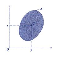
Figure 2 Centroid Location
Note: Analyzing the integrals contained in the equations (4) and (5), the
following important conclusions regarding the position of the centroid ![]() may be drawn:
may be drawn:
(a) if the cross-section
area possesses one axis of symmetry, the centroid ![]() lies on that axis;
lies on that axis;
(b) if the cross-section
area possesses two axes of symmetry, the centroid ![]() is located at their
intersection;
is located at their
intersection;
(c) if the cross-section
area is symmetric about a point, the centroid ![]() is located at the location of that point.
is located at the location of that point.
These cases are illustrated in Figure
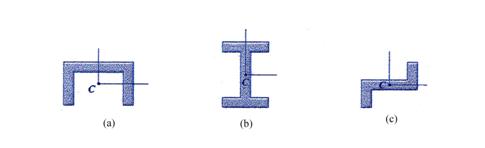
Figure 3 Types of Symmetry for Plane Area
(a) One Symmetry Axis, (b) Two Symmetry Axes and (c) Point Symmetry
The second moments of the cross-section area ![]() about the coordinate
system axes
about the coordinate
system axes ![]() and
and ![]() are called the moments
of inertia and are defined as (see Figure 4 for notation) :
are called the moments
of inertia and are defined as (see Figure 4 for notation) :
![]() (6)
(6)
![]() (7)
(7)
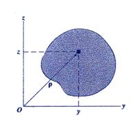
Figure 4 Second Moments of Inertia Notation
The summation of the moment of
inertia ![]() and
and ![]() is called the polar
moment of inertia and represents the second moment of inertia about the
axis
is called the polar
moment of inertia and represents the second moment of inertia about the
axis ![]() normal to the cross-section. The polar moment of inertia is
defined as:
normal to the cross-section. The polar moment of inertia is
defined as:
![]() (8)
(8)
The unit of the second moments of inertia is [L4].
Note: The second moments of inertia are always positive values.
Another important geometric
property is the product of inertia
of the area ![]() also called in the
Romanian technical literature the centrifugal
moment of inertia. The definition of the centrifugal moment of inertia is given
in equation (9):
also called in the
Romanian technical literature the centrifugal
moment of inertia. The definition of the centrifugal moment of inertia is given
in equation (9):
![]() (9)
(9)
The unit of the product of inertia is [L4].
Note: Contrary to the moments of inertia which are always positive
values, the product of inertia moment of inertia may have either a positive or
negative value. If the area ![]() has an axis of
symmetry the product moment of inertia
has an axis of
symmetry the product moment of inertia ![]() .calculated for a coordinate system including that axis is zero.
.calculated for a coordinate system including that axis is zero.
Parallel-Axis Theorems for Moment of Inertia
The above described moments of
inertia are usually calculated relative to a coordinate system ![]() anchored at the cross-section
centroid
anchored at the cross-section
centroid ![]() . A new translated coordinate system
. A new translated coordinate system![]() , with axes
, with axes ![]() and
and ![]() parallel to the centroidal
axes
parallel to the centroidal
axes ![]() and
and ![]() , respectively, is defined in Figure 5. The correspondence
between the moments of inertia relative to this new coordinate system
, respectively, is defined in Figure 5. The correspondence
between the moments of inertia relative to this new coordinate system ![]() and those calculated with
respect to the centroidal coordinate system
and those calculated with
respect to the centroidal coordinate system ![]() is studied in this
section.
is studied in this
section.
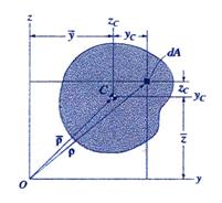
Figure 5 Parallel-Axis Theorems Notation
The position ![]() of an arbitrary point located
on the cross-section area
of an arbitrary point located
on the cross-section area ![]() expressed relative to
the
expressed relative to
the ![]() coordinate system is
written as:
coordinate system is
written as:
![]() (10)
(10)
![]() (11)
(11)
where the distances ![]() and
and ![]() are the horizontal and
vertical distances, respectively, between the two coordinate systems considered.
are the horizontal and
vertical distances, respectively, between the two coordinate systems considered.
The moments of inertia about axes
![]() and
and![]() ,
, ![]() and
and![]() , are expressed in the equations (6) and (7), respectively. Substitution
of equations (10) and (11) into equations (6) and (7) yields the following new
expressions for the moments of inertia:
, are expressed in the equations (6) and (7), respectively. Substitution
of equations (10) and (11) into equations (6) and (7) yields the following new
expressions for the moments of inertia:
![]() (12)
(12)
![]() (13)
(13)
Note that the integrals ![]() and
and ![]() become zero when the
static moments are calculated relatively to the centroidal axes.
become zero when the
static moments are calculated relatively to the centroidal axes.
The moments of inertia calculated about centroid axes are expressed as:
![]() (14)
(14)
![]() (15)
(15)
Substituting equations (14) and (15)
into equations (12) and (13) final expressions of the moments of inertial
calculated about the axes of the translate system ![]() are obtained as:
are obtained as:
![]() (16)
(16)
![]() (17)
(17)
Equations (16) and (17) are called the parallel-axis theorem for moments of inertia.
Note: Examination of equations (16) and (17) shows that the minimum
values for the moments of inertia are obtained when the axes ![]() and
and![]() are coincident with the centroidal axes
are coincident with the centroidal axes ![]() and
and ![]() , respectively.
, respectively.
A similar approach can be used for
the case of the polar moment of inertia ![]() defined by equation (8). Substituting equations (10) and (11)
into equation (8), the polar moment of inertia about point
defined by equation (8). Substituting equations (10) and (11)
into equation (8), the polar moment of inertia about point ![]() is obtained as:
is obtained as:
![]() (18)
(18)
Grouping the terms in the equation (18), the final expression may be written as:
![]() (19)
(19)
where ![]() and
and ![]()
Equation (19) represents the parallel-axis theorem for the polar moment of inertia.
The parallel-axis theorem for the product of inertia is derived in a similar manner to that for the moments of inertia. By substitution of equations (10) and (11) into equation (9), the following expression is obtained:
 (20)
(20)
Since the coordinate system ![]() passes through the
centroid of the cross-section the integrals representing the static moments are
zero and consequently, the equation (20) reduces to:
passes through the
centroid of the cross-section the integrals representing the static moments are
zero and consequently, the equation (20) reduces to:
![]() (21)
(21)
Equation (21) represents the parallel-axis theorem for the product of inertia.
Moment of Inertia about Inclined Axes
Consider Figure 6 where a new
coordinate system ![]() is shown rotated by an
angle
is shown rotated by an
angle ![]() from the position of
the original coordinate system
from the position of
the original coordinate system![]() . The rotation angle
. The rotation angle ![]() is positive when
increasing in the trigonometric positive sense (counter-clockwise). This
convention corresponds to the right-hand rule previously used.
is positive when
increasing in the trigonometric positive sense (counter-clockwise). This
convention corresponds to the right-hand rule previously used.
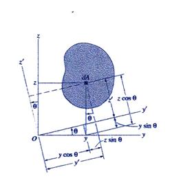
Figure 6 Axes Rotation Notation
The position ![]() of a current point located in the cross-section
of a current point located in the cross-section ![]() relative to the
coordinate system
relative to the
coordinate system ![]() can be written as:
can be written as:
![]() (22)
(22)
![]() (23)
(23)
Accordingly, with the definition equations (6) and (7) the
moments of inertia in the rotated coordinate system ![]() follow as:
follow as:
![]() (24)
(24)
![]() (25)
(25)
After algebraic manipulations the moments of inertia ![]() and
and ![]() are obtained as:
are obtained as:
![]() (26)
(26)
![]() (27)
(27)
Further, the equations (26) and (27)
are expressed in an alternative form by substitution of the double angle![]() formulae:
formulae:
![]() (28)
(28)
![]() (29)
(29)
The product of inertia ![]() is defined as:
is defined as:
 (30)
(30)
After the algebraic manipulations, the equation (30) becomes:
![]() (31)
(31)
Further more, the equation (31) is
re-written using the double angle![]() as:
as:
![]() (32)
(32)
If the derivatives of the moments of inertia shown in
equations (28) and (29) are taken relative to the double angle ![]() an interesting result is obtained:
an interesting result is obtained:
![]() (33)
(33)
![]() (34)
(34)
Note: The first derivative of the moment of inertia relative to the
double angle![]() is
the product of inertia.
is
the product of inertia.
The sum of equations (28) and (29) reveal the following important relationship:
![]() (35)
(35)
Note: Equation (35) indicates the invariance of the sum of the moments of inertia with the rotation of the axes.
Principal Moments of Inertia
The moments of inertia ![]() and
and![]() , expressed by equations (28) and (29), are functions of the
angle
, expressed by equations (28) and (29), are functions of the
angle ![]() of the rotated
coordinate system
of the rotated
coordinate system![]() . The extreme values (the maximum and minimum) of the moments
of inertia
. The extreme values (the maximum and minimum) of the moments
of inertia ![]() and
and![]() are called principal
moments of inertia. The corresponding values of the rotation angle
are called principal
moments of inertia. The corresponding values of the rotation angle ![]() describe the principal axes of inertia. The principal axes of inertia passing
through the centroid of the cross-section area are called centroidal principal axes of inertia.
describe the principal axes of inertia. The principal axes of inertia passing
through the centroid of the cross-section area are called centroidal principal axes of inertia.
As known from Calculus, the
condition for a real function to have an extreme point (a maximum or minimum) is
that the first derivative of the function be equal to zero at that point. For
the case of the moments of inertia![]() and
and![]() , using equation (33) and (34), the condition of extreme, is
written as:
, using equation (33) and (34), the condition of extreme, is
written as:
![]() (36)
(36)
From equation (36) the value of the angle ![]() corresponding to the
principal directions is obtained as:
corresponding to the
principal directions is obtained as:
![]() (37)
(37)
From the trigonometry, it is
known that equation (37) has two solutions, ![]() and
and ![]() , related as shown in the equation (38):
, related as shown in the equation (38):
![]() (38)
(38)
Consequently, it is concluded that the principle directions are perpendicular to each other:
![]() (39)
(39)
Using the following trigonometric identities
 (40)
(40)
 (41
(41
and substituting them into equations (33) and (34) the final expressions for the principle moments of inertia are obtained as:
 (42)
(42)
 (43)
(43)
Note: The invariance of the sum of the moments of inertia is also preserved for the case of the principal moments of inertia. By addition of equations (42) and (43) the invariance is proven:
![]() (44)
(44)
To identify which of the two angles, ![]() or
or![]() , corresponds to the maximum moment of inertia
, corresponds to the maximum moment of inertia ![]() the second derivative
of the function
the second derivative
of the function![]() , shown in equation (28), is used. The condition for the point
to be a maximum is:
, shown in equation (28), is used. The condition for the point
to be a maximum is:
 (45)
(45)
The expression (45) is re-written as:
![]() (46)
(46)
After the trigonometric manipulations and the usage of the equation (37) the inequality (46) became:
 (47)
(47)
The condition for the inequality (47) to hold is:
![]() (48)
(48)
Note: Here, in order for inequality (48) to hold true, the sign of
product of inertia ![]() must be opposite to that of the tangent of the angle
must be opposite to that of the tangent of the angle ![]() .
.
Practically, the angle corresponding to the direction of the
maximum moment of inertia is obtained by successively assigning to angle ![]() the values
the values ![]() and
and ![]() and identifying which
angle verifies the inequality (48).
and identifying which
angle verifies the inequality (48).
Maximum Product Moment of Inertia
Consider the angle of the
principal directions![]() established and the original coordinate system
established and the original coordinate system![]() shown in Figure 6 rotated such that the
shown in Figure 6 rotated such that the ![]() and
and ![]() axes align with the principal directions. Then, the following
expressions hold:
axes align with the principal directions. Then, the following
expressions hold:
![]() (49)
(49)
![]() (50)
(50)
![]() (51)
(51)
Substituting equations (49) through (51) into the equations (28), (29) and (32) the expression for the moments of inertia as functions of the principal moments of inertia are obtained:
![]() (52)
(52)
![]() (53)
(53)
![]() (54)
(54)
From equation (54), it is easy to see that the maximum value for the product of inertia is obtained when:
![]() (55)
(55)
Then,
![]() (56)
(56)
The maximum value of the product
of inertia is obtained for an angle of rotation ![]() measured in the counter-clockwise
direction from the position of the principal axes is expressed in equation (57).
measured in the counter-clockwise
direction from the position of the principal axes is expressed in equation (57).
![]() (57)
(57)
Substituting the principal moments of inertia given by
equations (43) and (44) and (42) into equation (57) a new expression for the ![]() is obtained:
is obtained:
 (58)
(58)
The corresponding moments of inertia are obtained by
replacing ![]() in equations (52) and
(53):
in equations (52) and
(53):
![]() (59)
(59)
Mohrs Circle Representation of the Moments of Inertia
A very interesting and useful
relationship, shown in equation (60), is obtained by manipulating the equations
(28) and (32) in the following manner: (a) the equation (28) is rearranged by
moving in the left hand side the term ![]() and then squaring both
sided of the equation, (b) the equation (332) is squared and (c) adding
together the previous obtained equations
and then squaring both
sided of the equation, (b) the equation (332) is squared and (c) adding
together the previous obtained equations
![]() (60)
(60)
The following notation is employed in the implementation of the equation (60):
![]() (61)
(61)
![]() (62)
(62)
 (63)
(63)
![]() (64)
(64)
Substitution of equations (61) through (64) into the equation (60) yields a new form for equation (60)
![]() (65)
(65)
Geometrically, equation (65)
represents the equation of a circle located in the ![]() plane. The circle has center
plane. The circle has center ![]() located at
located at ![]() and radius
and radius![]() .
.
The coordinates of the intersection
points, ![]() and
and![]() , between the circle and the horizontal axis
, between the circle and the horizontal axis![]() , are obtained by solving the algebraic system composed of
equation (65) and the equation of the axis
, are obtained by solving the algebraic system composed of
equation (65) and the equation of the axis![]() :
:
![]() (66)
(66)
![]() (67)
(67)
Substituting equations (63) and (64)
into equations (66) and (67) the position of the intersection points![]() and
and![]() are expressed as shown in equations (68) and (69) and are
identified as the principal moments of inertia.
are expressed as shown in equations (68) and (69) and are
identified as the principal moments of inertia.
 (68)
(68)
 (69)
(69)
The graphical representation of the Mohrs circle is depicted in Figure 7.
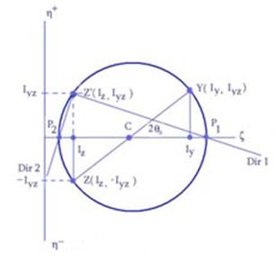
Figure 7 Morhs Circle Representation
Note: Practically the Mohrs circle is constructed using the following steps:
(a)
The coordinates system ![]() is drawn as shown in
Figure 2.7. The horizontal axis
is drawn as shown in
Figure 2.7. The horizontal axis ![]() represents the moments
of inertia, while the vertical axis
represents the moments
of inertia, while the vertical axis ![]() represents the product
of inertia (note that the positive axis
represents the product
of inertia (note that the positive axis ![]() is drawn upwards).
The drawing should be done roughly to scale. The representation considers that
the following conditions are met:
is drawn upwards).
The drawing should be done roughly to scale. The representation considers that
the following conditions are met:![]() ,
, ![]() ,
, ![]() and
and ![]() ;
;
(b)
Using the calculated values of the
moments of inertia![]() and
and![]() and the product of inertia
and the product of inertia![]() two points noted as
two points noted as ![]() and
and ![]() are placed on the
drawing. The line
are placed on the
drawing. The line ![]() intersects the
horizontal axis in point
intersects the
horizontal axis in point ![]() which represents the
center of the Mohrs circle;
which represents the
center of the Mohrs circle;
(c)
The distance ![]() is the radius of the circle. Using the radius
is the radius of the circle. Using the radius ![]() and the position of the center
and the position of the center ![]() the Mohrs circle is
constructed. The intersection points,
the Mohrs circle is
constructed. The intersection points, ![]() and
and![]() , between the circle and the horizontal axis represent the
maximum and the minimum moments of inertia;
, between the circle and the horizontal axis represent the
maximum and the minimum moments of inertia;
(d)
The absolute value of the ![]() can be calculated from
the graph;
can be calculated from
the graph;
(e)
The angle of the principal direction 1 is
the angle measured in the counter-clockwise direction between lines CY and CP1.
To obtain the position of the two principal directions corresponding to the cross-section
system ![]() an additional point
Z, the reflection of the point Z in reference to axis
an additional point
Z, the reflection of the point Z in reference to axis ![]() , has to be constructed. The lines ZP1 and ZP2 represent
the principal direction 1 (associated with the maximum moment of inertia) and 2
(associated with the minimum moment of inertia), respectively. The two
directions can then be transcribed on the cross-section sketch.
, has to be constructed. The lines ZP1 and ZP2 represent
the principal direction 1 (associated with the maximum moment of inertia) and 2
(associated with the minimum moment of inertia), respectively. The two
directions can then be transcribed on the cross-section sketch.
Radii of Gyration
The square root of the ratio of the moment of inertia to the area is called the radius of gyration and has the unit of [L].
The radii of gyration relative to
the original coordinate system ![]() are calculated as:
are calculated as:
![]() (70)
(70)
![]() (71)
(71)
For the case of the principal moments of inertia, the corresponding radii of gyration are:
![]() (72)
(72)
![]() (73)
(73)
Examples
To clarify the theoretical aspects and the formulae derived in this lecture, two examples are presented.
8.1 Rectangle Cross-Section
A rectangular cross-section is
shown in Figure 8. The rectangle is characterized by two symmetry axes and
consequently, the centroid ![]() is located at their
intersection. The coordinate system used is the centroidal coordinate system
shown in the Figure 8.
is located at their
intersection. The coordinate system used is the centroidal coordinate system
shown in the Figure 8.
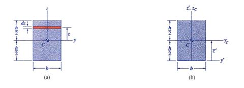
Figure 8 Rectangular Cross-Section
The following cross-sectional characteristics are calculated using the formulae previously developed:
![]()
![]() =0
=0
![]() =0
=0
![]()
![]()
![]()
It is shown thus, that for a
rectangular cross-section the centroidal coordinate system represents the
principal axes of inertia![]() .
.
If the moment of inertia about the axis coinciding with the lower edge of the rectangle is required, using the notation shown in Figure 8(b), the parallel-axis theorem for moments of inertia is employed:
![]()
8.2 Composite Cross-Section
The L-shaped cross-section illustrated
in Figure 9(a) is proposed for investigation. The vertical and horizontal legs
have a height of ![]() and
and![]() , respectively, while thickness
, respectively, while thickness ![]() is uniform for the
entire figure. The L-shaped cross-section can be decomposed into two
rectangular areas,
is uniform for the
entire figure. The L-shaped cross-section can be decomposed into two
rectangular areas, ![]() and
and ![]() , representing the areasof the individual legs of the
cross-section. The distances of the centroids,
, representing the areasof the individual legs of the
cross-section. The distances of the centroids,![]() and
and![]() , of the two rectangular areas are positioned relative to the
coordinates system
, of the two rectangular areas are positioned relative to the
coordinates system ![]() without any difficulty
as depicted in Figure 9(b).
without any difficulty
as depicted in Figure 9(b).
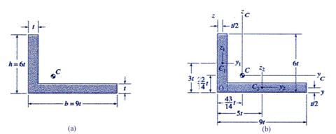
Figure 9 L-Shaped Cross-Section
The individual area of each leg and total area of the L-shaped cross-section are calculated as:
![]()
![]()
![]()
The position of the cross-section
centroid ![]() is obtained:
is obtained:
![]()
![]()
![]()
![]()
A new coordinate system aligned
with the system ![]() and with the origin at the centroid
and with the origin at the centroid ![]() of the entire cross-section is established as
of the entire cross-section is established as ![]() . The following calculations are performed with reference to
this centroidal coordinate system. The moments of inertia about the centroidal
coordinate axes are calculated as:
. The following calculations are performed with reference to
this centroidal coordinate system. The moments of inertia about the centroidal
coordinate axes are calculated as:
The principal moments of inertia are obtained as:
The angle of the principal direction of inertia is calculated as:
![]()
![]()
Using the test contained in the
equation (48) to determine if the rotation angle![]() is the angle of the principal direction results in the
following:
is the angle of the principal direction results in the
following:
![]()
Consequently, the angle ![]() is the angle of the direction of the minimum moment of
inertia and
is the angle of the direction of the minimum moment of
inertia and![]() , while the complementary angle
, while the complementary angle ![]() represents the direction of the maximum moment of inertia.
represents the direction of the maximum moment of inertia.
The angles ![]() and
and ![]() are illustrated in Figure 10.
are illustrated in Figure 10.
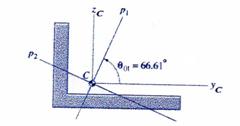
Figure 10 L-Shaped Cross-Section Principal Directions
The radii of gyrations are obtained as:
![]()
![]()
![]()
![]()
The construction of the Mohrs circle is conducted as explained in Section 6. Using the moments and the product of inertia calculated above the following values are determined:
![]()
![]()
![]()
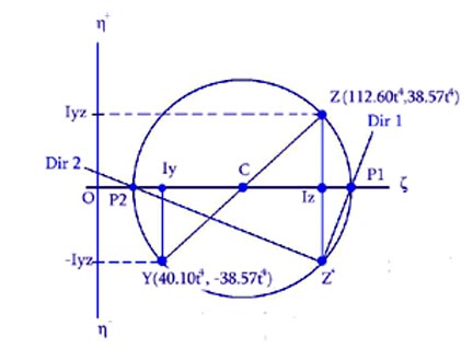
Figure 11 L-Shaped Cross-Section Mohrs Circle
|
Politica de confidentialitate | Termeni si conditii de utilizare |

Vizualizari: 2022
Importanta: ![]()
Termeni si conditii de utilizare | Contact
© SCRIGROUP 2025 . All rights reserved