| CATEGORII DOCUMENTE |
| Bulgara | Ceha slovaca | Croata | Engleza | Estona | Finlandeza | Franceza |
| Germana | Italiana | Letona | Lituaniana | Maghiara | Olandeza | Poloneza |
| Sarba | Slovena | Spaniola | Suedeza | Turca | Ucraineana |
High-Current Bus-Powered Devices
There are several things to consider when designing a high current, bus powered device with the FT8U232 or FT8U245 chips :
1. The high power logic can only be switched on if the system configures the device.
The power to the extra logic must be controlled by a device to ensure it is powered off when the device is first plugged in. If you are plugged into a bus-powered hub and you want more than 100mA, then you will not be configured. In addition, it is advisable to prevent sudden changes in power requirements. These can cause the voltage rail to drop down to 3 volts, although momentarily, and cannot be smoothed by capacitance alone.
The following circuit does two functions. It allows the power to the load to be switched off and on, and it provides a 'slow start' feature to prevent VCC glitches. For Q1 a BCP69 - SOT223 or a ZTX718 - E line or similar can be used.
The following oscilloscope trace shows the circuit driving a 25 Ohm / 5uF load.
2. The high power part must be powered down during suspend or reset.
For
the FT8U232 device the -
For the FT8U245 device it needs to be a bit more complex. To indicate that the device has been configured a latch arrangement should be used. If RESET# is used to pull up RCCLK instead of VCC, then RCCLK can be used to set the latch output high (OFF - The output of the NAND gate is driving -Load On). If RXFULL# goes low this can be used to reset the latch output low, and turn the power on. In this manner, the device is powered up by writing a byte to it.
3. Telling the system that you need more than 100 mA.
This is done in the EEPROM. A field is available that specifies the milliamps required. The application FTD2XXST.exe is used to program the EEPROM. An example of the screens now follows.
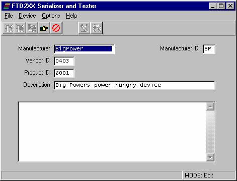
Start the application and select 'FileNew' if you have run it before. You should have an empty screen like the following :
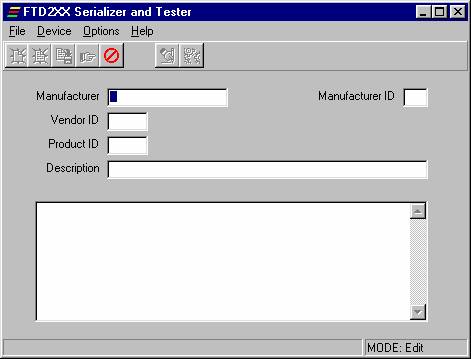
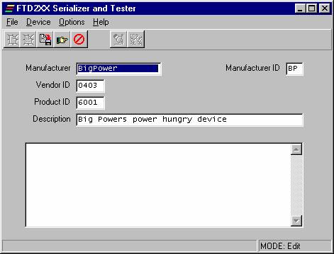
Next fill in the required fields. Use the TAB key to move between fields. You will notice that when you have filled in all the fields and gone back to the beginning, that the hand with pointing finger is highlighted in the toolbar. The following is an example :
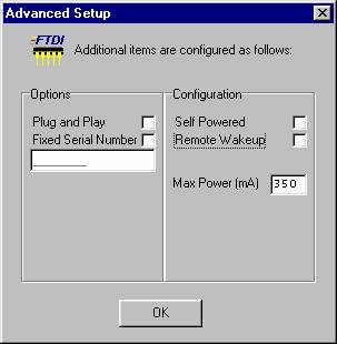
Next click on the hand in the toolbar and select what is appropriate to your device. You should make it 'not Self Powered' and put in an appropriate amount into the 'Max Power' field. The maximum allowable is 500mA but don't specify this. Say 490mA instead.
Click 'OK' and you will go back to the main screen with another option highlighted in the toolbar.
This saves the information for you and will then let you advance to program the device as follows.
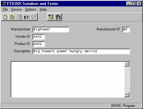
Now press the button with the hand and the pen. You should see the following screen after you have successfully programmed a device, although the serial number will be different.
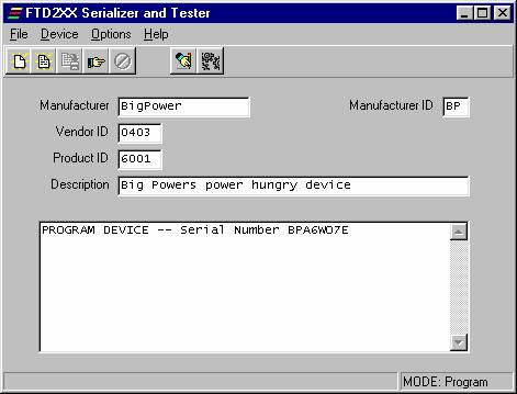
The device is now ready to use.
|
Politica de confidentialitate | Termeni si conditii de utilizare |

Vizualizari: 1428
Importanta: ![]()
Termeni si conditii de utilizare | Contact
© SCRIGROUP 2026 . All rights reserved