| CATEGORII DOCUMENTE |
| Bulgara | Ceha slovaca | Croata | Engleza | Estona | Finlandeza | Franceza |
| Germana | Italiana | Letona | Lituaniana | Maghiara | Olandeza | Poloneza |
| Sarba | Slovena | Spaniola | Suedeza | Turca | Ucraineana |
The size of the turbo selected for a given application will strongly influence the degree of success enjoyed by the system. It is not at all a case of only one size working in a specific situation; rather, there is just one that will work best. The trade-offs of lag, boost threshold, heat, low-speed torque, and power are the variables in the decision process of matching the turbo to the requirements. To optimize the trade-offs, the requirements must be defined first. These requirements can be spelled out by listing the performance objectives for the particular vehicle.
Objectives can vary for day-to-day commuter cars, Bonneville maximum-speed cars, drag cars, super-performance street cars, real race cars, and even for the outer fringe of vehicles called pickup trucks. Specific performance objectives will be items such as desired boost threshold, torque peak, and estimated power output. Higher-speed vehicles require larger turbos, street cars respond well to mid-range torque, and low-speed vehicles need smaller turbos. How to select the right turbo for the job and how to choose some of the more advantageous features are discussed in the following paragraphs.
To illustrate the degree to which turbo sizing can vary for the particular job, compare the 1988 Nissan 300ZX Turbo and the Porsche 911 Turbo. These two cars are similar in size, weight, and engine displacement, yet the turbos are vastly different in size. From the size of the Porsche's turbo, it id relatively easy to conclude that the Porsche design staff did exactly what they needed to do. They fitted a large turbo to the 911, for three specific reasons:
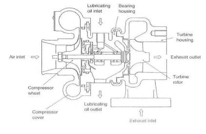
Fig. 3-1. The classic turbocharger: a very simple, highly engineered, high-quality, precisely manufactured air pump..
When operating at maximum load, the large compressor puts less heat into the intake charge.
The large turbine creates less exhaust manifold back pressure, further
reducing the heat load.
The design staff wanted a powerful automobile.
The Nissan staff, on
the other hand, with a much more heat-tolerant engine (water-cooled), way free
to use a small turbo for virtually immediate off idle response. This small
turbo gives quick boost response at the extreme expense of high back pressure
and high intake-charge temperatures. Nissan was obviously not looking for
serious power, as they did not see fit to offset these high temperatures with
any form of intercooling. Their objective appears to have been aimed at a 0-
The influence of compressor and turbine sizes on system performance will generally follow these guidelines:
A compressor has a particular combination of airflow and boost pressure at which it is most efficient. The trick in choosing optimum compressor size lies in positioning the point of maximum efficiency at the most useful part of the rev rangy. Choosing the most useful part of the rev range is where some judgment needs to be exercised. Keep in mind at all times that when efficiency drops off', heat produced by the turbo goes up. If a turbo were sized such that maximum efficiency occurred at one-third of the rev range, efficiency at or near the redline would taper off to where the charge temperature would be scorching hot. At the other extreme, if maximum efficiency were at the redline, mid-range temperatures could get out, of hand. This particular size would then be useful only for running flat out at that rpm; i.e., the Bonneville car. Somewhere in the middle of the useful rev range of the engine lies the best place to locate the maximum efficiency point.
Larger or smaller compressors do not have a huge effect on turbo lag or boost threshold. The compressor wheel is the lightest rotating part of the turbo; hence, its contribution to the total inertia of the rotating assembly is fairly low. Boost threshold is mostly a function of the turbo's speed, which is controlled by the turbine.
Often, a choice of turbo(s) is influenced by factors other than those optimized by thermodynamics or maximum power. Vehicle cost can determine the number of turbos, for example. One would not expect to see a Ferrari V-12 with one turbo and a Mazda Miata with two. Cost also plays a large part in designing a system. If low cost is imperative, perhaps even the water-cooled bearing feature would be deleted in favor of more frequent oil change.
Ultimately, the value of the equipment selected will not lie just with coat, power, thermodynamic factors, or the number of turbos. Rather, it will be determined by the way this baby behaves on the road. Is it actually fast, and does it fee] fast? Does it feel responsive and eager to run? Is it crisp and sharp? Does it pull smoothly with ease and grace to the redline? Does it make you smile when no one is around to see?
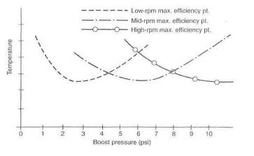
Fig. 3-2. With a small turbo, the maximum efficiency point peaks early, and temperatures will be lowest at low boost pressures. To keep temperatures down at high power outputs, a large turbo is clearly necessary.
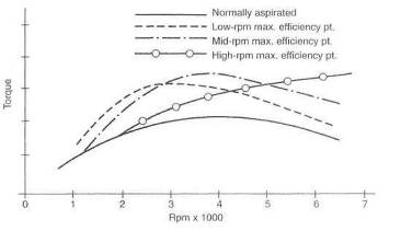
Fig. 3-3. An the maximum efficiency point, occurs at higher and higher rpm, cooler temperatures also occur. Cooler temperatures mean denser air, which keeps torque peaks at higher rpm.
Start by selecting two or three candidates whose pressure ratio and cfm appear, from their flow maps, to be in the right range, with efficiency not below 60%, Once this is accomplished, it is necessary to perform calculations to choose between them. (See Chapter 17 for an example of these calculations applied to a specific installation.)
The turbine's role is to power the compressor, In doing so, it must make the compressor spin fast enough to produce the desired airflow rates at the designated boost pressures, A small turbine will spin faster than a larger turbine, given the same exhaust gas energy to work with. Further, a small turbine will offer, in essence, a greater restriction to the flow of the exhaust gases. This restriction causes back pressure between the turbine and the combustion chamber. This back pressure is an evil side effect of the turbocharger and must be dealt with accordingly. In reality, then, selection of the turbine must focus on the principles of spinning the turbine fast enough to produce the desired response and boost pressures yet keeping back pressure to an absolute minimum.
A few fundamentals must be understood prior to the actual process of choosing compressor size. It is necessary to develop a feel for the concepts of pressure ratio, airflow rate, density ratio, and compressor efficiency before one can be comfortable with the logic behind choosing a compressor size.
The pressure ratio is the total absolute pressure produced by the turbo divided by atmospheric pressure. Absolute pressure means the amount of pressure above nothing at all. Nothing at all is zero absolute, so atmospheric is 14.7 absolute. Two psi boost becomes 16.7 absolute, 5 psi boost is 19.7 absolute, and so on. Total absolute pressure is then whatever the gauge reads plus 14.7. The pressure ratio thus becomes a reflection of the number of atmospheres of pressure generated.
![]()
![]()
Example:
For 5 psi boost:
![]()
In this example, approximately 34% more air will go into the engine than the engine could have consumed by itself. For 12 psi boost:
![]()
Here, approximately 82% more air will be going through the system. Pressure is also measured in bar, short for barometric (1 bar = 14.7 psi). In the above example, a pressure ratio of 1.82 equates to an intake pressure of 1.82 bar. This term is used in high-class turbo circles (which explains why it does not appear again in this book).
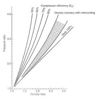
Fig. 3-4. Compressor density ratio versus pressure ratio. Density is degraded by temperature; therefore, actual air-mass increase is always less than that indicated by the pressure ratio.
Ultimately, power produced by turbocharging depends on the number of air molecules packed into each cubic inch of volume. This is referred to as the density of the air charge. This density takes a bit of a beating in passing through the turbocharger system. When the air molecules are forced closer together by the turbo to a certain pressure ratio, density does not increase by (he same ratio. This is because compression makes the temperature rise, and the air molecules expand back apart, based on how hot the air gets. Although the air charge winds up denser, density is always less than the pressure ratio, as indicated in figure 3-4. (Since the air intake system is not a fixed volume, air density can decrease without the pressure ratio decreasing.) The effort expended by a designer to use efficient compressors and intercoolers allows the density ratio to get closer and closer to the pressure ratio but never quite reach it.
The airflow rate through an engine is usually referred to as cubic feet per minute (dm) of air at standard atmospheric pressure. The technically correct but less-used term is pounds of air per minute. This book will use the semi-incorrect term 'cfm.'
To calculate the airflow rate of an engine without a turboi.e. no boost:
![]()
Here, flow rate is in
cfm and displacement is in cubic inches. The .5 is due to the fact that a
four-stroke-cycle engine fills its cylinders only on one-half the revolutions, ![]() is volumetric efficiency. The 1728 converts
cubic inches to cubic feet.
is volumetric efficiency. The 1728 converts
cubic inches to cubic feet.
Example;
In a small-block Ford,
let size = 302 cid, rpm = 5500, and ![]() = 85%.
= 85%.
Then
![]() cfm
cfm
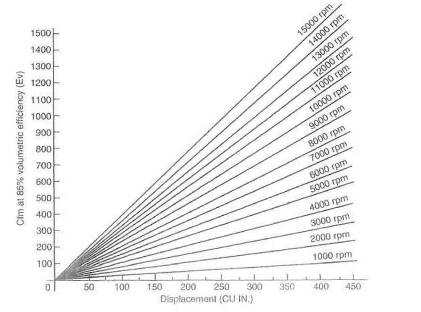
Fig. 3-5. The volume rate of flow (cfm) for four-stroke-cycle engines. Choose an engine size (the x-axis) and an rpm, and the cfm is shown on the y-axis.
With the basic engine flow rate established, the flow rate under boost can be determined. The pressure ratio times the basic engine flow rate then becomes the approximate flow rate under boost (neglecting volumetric efficiency): the number we're really after. In the small-block Ford operating at 12 psi boost:
![]() cfm
cfm
To convert cfm to the more correct term of pounds of air per minute, cfm must be multiplied by the density of air at the working; altitude (see table 3-1).
In concept, compressor efficiency is a measure of how well the compressor wheel can pump air without heating the air more than thermodynamic law says It should. Thermodynamics says the air temperature should rise a certain amount based on the pressure ratio. That temperature rise would be called the ideal temperature rise. When the temperature is actually measured, it is always higher than the thermodynamic calculation indicates it should be. The measured temperature rise is, of course, the real temperature rise. The efficiency is the calculated temperature rise divided by the real temperature rise. In essence, efficiency is how well the compressor really behaves with respect to how well thermodynamics says it should behave.
All compressor wheels operate with peak percentage efficiencies in the seventies. Choosing compressor size becomes mostly a question of where that compressor's efficiency peaks with respect to the flow capabilities of the engine/turbo system.
With an understanding of the terms pressure ratio, density ratio, airflow rate, and compressor efficiency, the basic information necessary to select a compressor for a given application is at hand. In general, under 7 psi is low boost. 7-12 psi is medium boost, and over 12 psi is high boost. Working through the example of the small-block Ford with several choices of compressors will illustrate the process of calculation as well as the importance of placement of the efficiency peak, A study of Fig. 3-6 indicates the effect of a compressor's efficiency on charge temperatures.
|
Altitude (ft) |
Air pressure |
Temperature |
Relative |
|
(in. hg) |
(F) |
density |
|
|
Sea level | |||
|
| |||
Table 3-1. Variation of air pressure and temperature with altitude
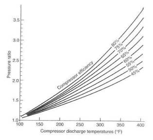
Fig. 3-6. Compressor discharge temperature versus pressure ratio. Why one wants to secure the highest compressor efficiency possible: the greater the efficiency, the lower the temperature.
In general, compressor efficiency without an intercooler should be at least 60%. If the system includes an intercoolers minimum efficiency can be somewhat less (see Chapter 5).
With the calculated values of the cfm and pressure ratio for the Ford 302 example, one is ready to go to the compressor maps to check where the efficiencies lie in order to determine a suitable compressor. Plot the calculated data of cfm = 743 and PR = 1.S2 on the axes of the compressor maps. The intersection of the two lines represents the maximum flow the compressor can produce at the pressure ratio for this application, and that point falls into a particular efficiency percentile on each map. It is largely the efficiency at this point that establishes the suitability of that compressor for the particular application. In figure 3-7, the intersection of these points falls along the 67% line. In figure 3-8, the intersection falls to the right of the 60% line, which indicates that the efficiency will be somewhat lessperhaps 50-65%. Therefore, the H-3 would be a less satisfactory choice for this application.
The surge characteristics of the compressor with regard to the application must also be examined before finalizing a selection. This can be approximated in a simple manner. Assume that the desired pressure ratio is reached at 50% of the redline rpm and plot this point on the compressor map. The above example with rpm = 2750 then establishes a point at cfm = 371 and PR = 1.82. Draw a tine from this point to a point at PR = 1 and cfm - 20% of maximum, or 149 cfm in this example. It is imperative that this line lie completely to the right of the line on the flow map called the surge limit. Surge limits are not always labeled on flow maps, but you can assume they are the leftmost line. This example indicates that the 60-1 compressor, at 67% efficiency, is better suited for this application than the H-3, at 55%.
The intended use of the engine/turbo system is again the primary influence on selection of turbine size. Intended use dictates a choice of low-speed, mid-range, or top-end torque. The choice can easily encompass two of these ranges.
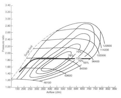
Fig, 3 7. Nearly 900 cfm are available from the Turbonetics 60-1 compressor with a pressure ratio of 2,8. The steep include of the surge limit line clearly indicates that the 60-1 will produce high boost pressures at low cfm before surge is produced The numbers at the extreme right are the turbine rpm.
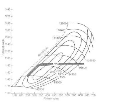
Fig. 3-8, The Turbonetics H-3 compressor will produce 750 cfm at a pressure ratio of 2.8, but this yields an efficiency of only 60%. Note how the surge line leans sharply to the right, indicating that the H-3 will not work at high boost pressures at low airflow rates.
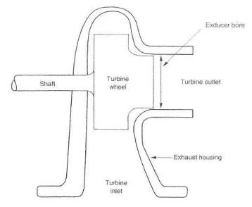
Fig. 3-9. Definition of the exducer bore
In making this selection, two quantities must be dealt with: basic turbine size and area/radius (A/R) ratio.
Consider basic turbine size a measure of the turbine's ability to generate the shaft power required to drive the compressor at the flow rates desired. Larger turbines, therefore, generally offer higher power outputs than smaller turbines. For a large measure of simplicity, turbine size can generally be judged by the turbine's exducer bore. While this is a gross simplification of the science of turbines, it is nevertheless a reasonable representation of the turbine's flow capability.
The graph of exducer bore versus intake cfm is not a selection tool but an approximate size indicator.
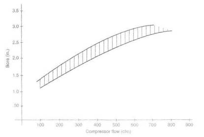
Fig. 3-10, Approximate exducer bore required to power a compressor to a given flow rate
A reasonable turbine selection method is to consult the source from whom you are purchasing the turbocharger. Certainly a choice will exist whether to err on the high side or the low side. Again, this choice falls within the scope of the original objectives of the turbo system, I will go for the higher side every time.
While basic turbine size reflects a measure of the turbine's flow capability, the A/R ratio is a method of fine tuning between basic sizes. To easily grasp the idea of an A/R ratio, imagine the turbine housing as nothing more than a cone wrapped around a shaft to look like a snail. Unwrap this cone and cut off the small end a short distance from the tip. The hole in the end of the cone is the discharge area. The area of this hole is the A of the A/R ratio. The size of the hole is significant, as it determines the velocity with which exhaust gases exit the turbine scroll and enter the turbine blades. For any given rate of flow, a smaller exit will require that the gases flow faster. Thus, the area of the exit is important in controlling the velocity of the gases as they enter the turbine blades. This velocity has much to do with controlling the actual speed of the turbine. It is necessary to keep In mind that the area of this exit is the controlling factor in the bad side-effect of exhaust gas back pressure and, thus, reversion into the combustion chambers.
The R of the A/R ratio is the distance from the center of the section area in the cone to the center of the turbine shaft. All As divided by their respective Rs will give the same dividend:
![]()
or
![]()
The R also has a strong influence in controlling turbine speed. If one imagines that the turbine blade tips will travel about as fast as the gas is moving when it enters the tip area, it is easy to see that a smaller R will impart a higher rotating speed to the turbine.
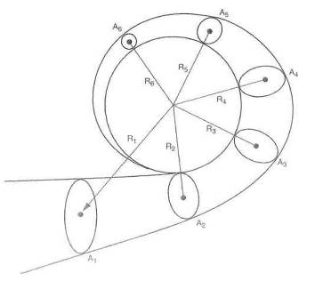
Fig. 3-11. Definition of the A/R ratio
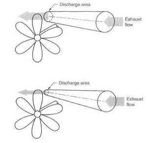
Fig, 3-12. To increase turbine speed, which varies with changes of the A/R ratio, it is almost always the discharge area thai is changed, with the radius remaining constant.
It is of further value to note that a larger R will effectively give the turbine shaft greater torque with which to drive the compressor wheel. The same force (exhaust gas) applied with a greater lever arm (R) puts more torque into the shaft. This, on occasion, can allow a bigger compressor wheel if conditions so require. In practice, however, it is almost always the A that is changed, while the radius remains constant. A simplified approach to choosing the A/R ratio is summed up in Fig. 3-13.
Selecting what appears to be a logical starting point for an A/R ratio is one thing, but actually getting the right one is yet another. Trial and error is usually necessary. A reasonable choice can be judged by the numbers, or to some extent by performance and response. Judging by the numbers requires measurement of exhaust manifold pressure, or turbine inlet pressure, and comparison with boost pressure.
The seat-of-the-pants feel of an improper A/R selection is sluggish boost rise if the ratio is too large. The ratio can be so big as to keep the turbo from turning fast enough to produce the desired boost. If the ratio is on the small side, the turbo response can be so quick as to seem jumpy and difficult, to drive smoothly. It will also show up as fading power in the upper third of the engine's rev range. The feel is similar to that of a normally aspirated engine with a very small carburetor 'Choked' is a reasonable description.
A split-inlet exhaust housing permits the exhaust pulses to be grouped (or separated) by cylinder all the way to the turbine. The merit of doing this is in keeping the individual package of energy, an exhaust putt., intact and unmolested by other putts all the way to the turbine. This can give the turbine a little better kick to get it moving. When you consider the absolute barrage of pulses and energy coming down the tube from an eight-cylinder -engine, the turbine will get more energy than it needs for almost any given situation.
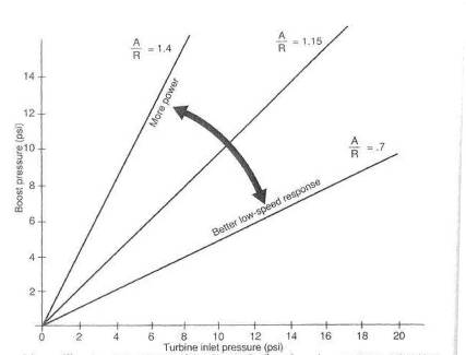
Fig. 3-13. The effect of varying the A/R ratio, all other factors remaining constant
Thus, a split housing
will make zip for improvement on a single-turbo V-
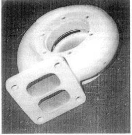
Fig. 3-14. The split-inlet exhaust housing theoretically offers a small performance advantage by keeping exhaust pulses in a tight bundle all the way to the turbine. This in more effective for engines with fewer cylinders, and thus fewer pulses, per engine cycle.
Several reasons exist for giving false consideration to using two turbos where one might otherwise do the job. Probably the most popular notion of the advantage of two turbos is reduced lag. This notion is generally hard to justify. Half the exhaust energy put through each of two turbines, with inertia proportional to the square and flow proportional to the cube, is not necessarily conducive to producing less lag. Multiple turbos imply more power Power is, in part, a function of efficiencies. All other things equal, a big turbo is more efficient than a small one. Pizzazz is a reasonable consideration when turbocharging a Ferrari, but the same logic cannot be applied to a turbo installation on a pickup truck. Good reasons do exist for using two turbos. This is particularly true with respect to V-style or horizontally opposed cylinder layouts.
Exhaust manifold design is one of the keys to high power output, and the two-turbo layout inherently offers superior manifold design. The heat loss of the cross tube in V-style engines can be considerable. Remember, it is in part this heat that powers the turbine.
A two-turbo design will usually require two wastegates. Other than the minor problem of synchronizing the two gates, much greater control of turbine speed at low boost pressures can be achieved. The stability of boost pressure at high flow rates is also improved. If remote wastegates are used rather than integrals, the actual exhaust gas flow area can be enlarged by giving the gates their own tailpipes.
Greater turbine
discharge area is always an improvement to the system. Turbine discharge pipes
from two turbos will virtually always give a large flow increase. For example,
two 2 1/4-inch-diameter tubes offer substantially more flow area than just one
of
A further reason two turbos offer superiority under certain conditions is that the heat is divided between two mechanisms, allowing each to operate with lower heat input. The heat absorbed into the materials of the turbo is proportional to the temperature of the gases and their mass rate of flow. The temperature will remain the same, but the mass rate of flow will be halved. Thus the operating temperature of the turbo will be reduced, and its life expectancy somewhat improved.
Water-cooled bearing sections. The water-cooled bearing is a feature that probably extends the average turbo's useful life by a factor of two. The presence of water flow through a jacket surrounding the bearing chamber greatly reduces temperature rise of the lubricating oil as it passes through the bearings. The reduced temperatures keep the oil from looking like Brand X in the Mobil 1 commercials. Charred oil residue accumulating inside the turbo and eventually blocking the oil flow, thus killing the turbo, is the dread disease called 'coked-up bearings.' (See chapter 4.) The water-cooled bearing was created because too many end users refused to change oil on a schedule dictated by the turbo. Ironically, the presence of the water-cooled bearing does not offer serious extension of oil-change intervals. Go straight to the best combination possible: water-cooled bearings and frequent oil changes.
Turbo section clocking. The rotation of one turbo section relative to another is called clocking. Although integral wastegates offer a measure of convenience in the design of noncompetition turbo systems, they usually do not allow the three sections of the turbo (turbine, bearing, and compressor) to be rotated 360* with respect to each other. Restrictions on clocking can seriously handicap packaging the turbo system into an engine compartment.
Connections to the turbo. The flanges on the turbine housing that connect the turbo to the exhaust manifold and tailpipe are two of the most common failure locations in the entire system. Heat-induced warpage, fastener, and gasket problems are relatively common. In general, flange configurations with more fasteners and thicker sections will endure the heat with fewer problems. Some turbos use a material called Ni-Resist for the exhaust housing. Ni-Resist is high in nickel and offers a worthwhile improvement in high -temperature stability, and thus durability, of the exhaust housing.
The compressor outlet is almost always a hose-style connection. Flexibility in this joint is usually desirable, to accommodate the moving around of the turbo caused by a stack-up of thermal expansions. High-boost-pressure systems may still need to add a connecting bar to the discharge; tube, to keep the hose connection intact under the high tensile loads caused by higher boost levels.
Compressor inlets are also generally configured with hose connections. These prove entirely adequate where fuel is not introduced before the turbo. In a draw-through carb application, the use of any hose between the carb and the turbo should be avoided, as fuel will puddle at the hose. A large-diameter hose boss permits a larger-diameter inlet system. Large-diameter, low-flow-loss inlets to the compressor are vital. Insure that all hoses are sufficiently stiff to avoid collapse due to the small vacuum created by the air filter and any associated air flowmeters.
How important is turbocharger sizing?
The turbo has got to be the right one for the job. The right turbo will offer a low rpm boost threshold, low system restriction, low charge temperatures, and low exhaust manifold pressure. Anyone with the ability to read and use a telephone can arrive at the right size turbo. No science, no magic, just a little R&D. For example, do you want the very lowest boost threshold? Well, maybe, if you drive only in five o'clock traffic. That is the only value a low boost threshold has. Be assured, the lower the boost threshold, the less the horsepower. On the other hand, if maximum power is your bag, the turbo size required probably won't produce any boost until the upper half of the rev range.
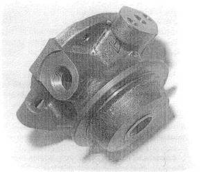
Fig. 3-15. The turbo bearing section with a water jacket offers extended turbo life and longer oil-change intervals.
This is impractical for the flexible requirements of a street turbo. Compromise at both ends is necessary. Don't fall for the journalistic gag that the merit of a turbocharger system is how soon it will produce boost
Does the brand of turbocharger affect performance ?
No. Virtually all turbo units are durable, responsive, and efficient. The performance of a kit. is in no way related to the turbo brand unless that brand is the only proper size available for the application. Some designs feature integral wastegates. These wastegates tend to require a bit more work to make them as effective as remote wastegates. In that situation the brand affects performance, but it's because of the integral wastegate.
Do twin turbos offer any advantage?
Sometimes. An engine with flow capabilities greater than 300 cfm (roughly 180 cid) can benefit from two turbos. Two little turbos can slightly cut turbo lag, as opposed to one large turbo, and allow a better balance of low-speed and top-end boost performance. Over 350 cid, twin turbos become a virtual necessity. Do not accept the idea that twin turbos are inherently more powerful, as too many other factors are involved.
What does compressor efficiency mean, and why is it important?
Compressor efficiency means nothing more than the real temperature of the air coming out of the turbo under boost relative to a calculated number based on thermodynamic equations. Calculate one, measure the other, divide the calculated by the measured, and you have compressor efficiency. Matching a compressor's efficiency to a particular engine is important, in that getting maximum efficiency somewhere near the power peak or maximum rpm means that the compressor has induced the lowest possible thermal load. 'Highly efficient' is a goofy expression invented by casual writers about turbos to mean nothing more than that whatever vehicle a turbo is on gets boost at low speeds. If something can be exactly wrong, this is an example of it. Iow-speed boost means small compressors that are inefficient at high speed. Thus, they produce high temperatures and are quite the opposite of 'highly efficient'
Does exhaust manifold pressure influence performance ?
Yes. Exhaust manifold pressure is a measure of how well the turbine unit is sized for the engine. Exhaust manifold pressure should not exceed approximately two and a half times the boost pressure. It is tempting for kit makers to use turbines too small for the job just to show a psi of boost at low rpm. Low rpm boost can be nice, but to overdo it means a severe (20% or so) loss of power above mid-range rpm. A proper balance of low versus top end is a development problem every kit maker should go through. Generally, less exhaust manifold pressure means more bhp. In other words, bigger turbines go faster.
|
Politica de confidentialitate | Termeni si conditii de utilizare |

Vizualizari: 2498
Importanta: ![]()
Termeni si conditii de utilizare | Contact
© SCRIGROUP 2025 . All rights reserved