| CATEGORII DOCUMENTE |
| Bulgara | Ceha slovaca | Croata | Engleza | Estona | Finlandeza | Franceza |
| Germana | Italiana | Letona | Lituaniana | Maghiara | Olandeza | Poloneza |
| Sarba | Slovena | Spaniola | Suedeza | Turca | Ucraineana |
BACKGROUND
Based on feedback from an in-service LPG carrier, some leakage through a thermal relief valve was observed. Further investigations onboard have been performed including stripping the valve down to component level this has identified some corrosion of the stainless steel guide (see FIG-1).
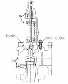
FIG-1 VALVE SECTIONAL VIEW
TECHNICAL EXPLANATION
Stainless steel does not normally corrode so further investigations by the manufacturer (Fukui) identified that the cause of the corrosion is not the stainless steel guide material, instead the problem is caused by the hardening process applied to the guide during manufacturing process. The process used is called Nitriding and is applied to valves with a set pressure above 20 bar and only for the thermal relief valve style with model numbers indicated below. The Nitriding process originally applied is a heat treatment process that chemically alters the surface to improve resistance to friction damage but does reduce the corrosion resistant properties of the materials. In this case the affected valves are potentially exposed to salty environment because they are connected to the cargo vent system open to atmosphere this reduced corrosion resistance and the exposure to the salty environment has caused the surface corrosion.
The proposal is that the all valves of this type on each project will have the original guide replaced with a new guide manufactured to the same dimensions and clearances however a different hardening method called WPC. The WPC hardening treatment is a well recognized shot-peening mechanical (rather than chemical) treatment which produces microscopic convexo-concave profile on material surface, and decreases contact resistance so the treated material has increased surface hardness resistance to friction damage is improved. The anti-corrosion performance is same as untreated material.
It is important to identify that other relief valve types (including cargo tank relief valves) do not have this hardening process applied and are therefore not affected. The purpose of the hardening process is to prevent galling between the same material type used for the guide and the holder so they can move freely and allow the valve to operate correctly.
The purpose of this guide is to provide a technical explanation of the remedial work required to replace the guide on affected valves. The work performed will not affect the set pressure of the valve, so re-testing and re-certifying of the valves is not required because no seals are broken.
For in-service
vessels, this work can be performed onboard and ideally the valve is removed
from the line so the work can be performed in a controlled environment and air
testing of the seat tightness (to 90% of valve set pressure) can be applied.
For in-construction vessels the work can be performed in-position and
AFFECTED MODELS
Affected models for guide replacement work are thermal relief valves as follows.
 REC331-S1
RECL331-S1
REBL331-S1
REPLACMENT PROCEDURE
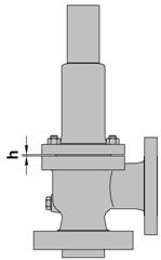
Measure a clearance h (FIG-2) between BODY and BONNET by clearance gauge (FIG-3)
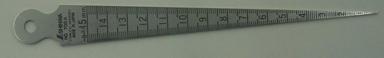 |
FIG-3 CLEARANCE GAUGE FIG-2 CLEARANCE h
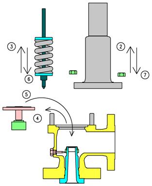 Loosen 4 nuts that hold BODY and BONNET evenly, then lift BONNET
up vertically.
Loosen 4 nuts that hold BODY and BONNET evenly, then lift BONNET
up vertically.
Remove SPINDLE, SPRING, WASHERS.
(In case a valve is lever installed type, above mentioned 3 parts are removed together with BONNET)
Remove DISC ASSY (DISC and HOLDER) with GUIDE, and replace EXISTING NITRIDED GUIDE with WPC TREATMENT GUIDE.
Replace new GASKETS and set DISC ASSY and GUIDE into BODY
Put SPINDLE. SPRING, WASHERS back in place
Put BONNET back in place and fasten 4 nuts evenly, then tighten again with torque wrench. (BOLT SIZE M12 Tightening torque:25N-m / BOLT SIZE M16 Tightening torque: 62N-m)
Measure a clearance h again to confirm a clearance is the same as before reassembling rate. FIG-4 REPLACEMENT PROCEDURE
|
Politica de confidentialitate | Termeni si conditii de utilizare |

Vizualizari: 3247
Importanta: ![]()
Termeni si conditii de utilizare | Contact
© SCRIGROUP 2026 . All rights reserved