| CATEGORII DOCUMENTE |
| Bulgara | Ceha slovaca | Croata | Engleza | Estona | Finlandeza | Franceza |
| Germana | Italiana | Letona | Lituaniana | Maghiara | Olandeza | Poloneza |
| Sarba | Slovena | Spaniola | Suedeza | Turca | Ucraineana |
Smart Car Seat
ABSTRACT
The goal of this project is to produce an innovative car seat that will prevent child deaths due to heat exhaustion or hypothermia caused by dangerous temperatures inside the vehicle. This product consists of two separate systems; a keychain system and a main system. They work in conjunction by activating alerts in the form of a beeper on the keychain and a panic alarm on the vehicle when the temperature is below 45 or above 80 degrees Fahrenheit. The main system will also unlock the doors on the vehicle when the panic alarm is activated, allowing for quick and safe removal of the child. The product utilizes two microcontrollers, two radio frequency modules, one beeper, one keyless entry system and three temperature sensors.
Purpose
The purpose of this project is to produce an innovative car seat that will prevent child deaths due to heat exhaustion or hypothermia caused by dangerous temperatures inside the vehicle. This product consists of two separate systems; a keychain system and a main system. They work in conjunction by activating alerts in the form of a beeper on the keychain and a panic alarm on the vehicle when the temperature is below 45 or above 80 degrees Fahrenheit. The main system will also unlock the doors on the vehicle when the panic alarm is activated, allowing for quick and safe removal of the child. The product utilizes two microcontrollers, two radio frequency modules, one beeper, one keyless entry system and three temperature sensors.
This product is extremely useful because it requires no external hardware, and can be immediately put into operation. Another feature is the efficient and long-lasting battery system.
Specifications
The main system circuit functions as specified:
Innovative buckle switch controls power to main system
Averages the temperatures of the three temperature sensors
Activates the panic alarm on the vehicle at temperatures below 45 and above 80 degrees Fahrenheit
Unlocks the doors on the vehicle at temperatures below 45 and above 80 degrees Fahrenheit
Transmits a high signal to the keychain system at temperatures below 45 and above 80 degrees Fahrenheit and transmits a low signal otherwise
The keychain system circuit functions as specified:
Activates the beeper alarm at temperatures below 45 and above 80 degrees Fahrenheit
Receives a high signal from the main system at temperatures below 45 and above 80 degrees Fahrenheit
Subprojects
This project is comprised of two systems; a main system and a keychain system.
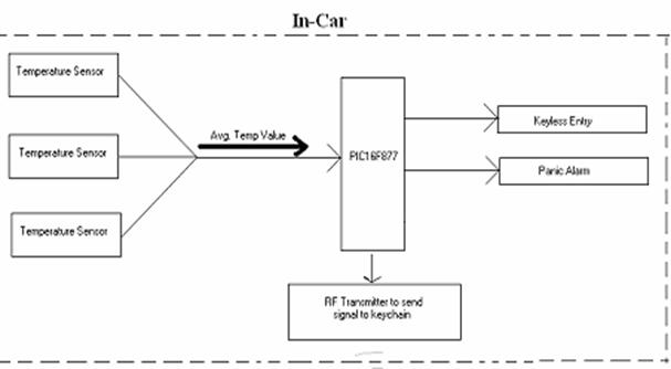

Figure 1. Block Diagram of Main System
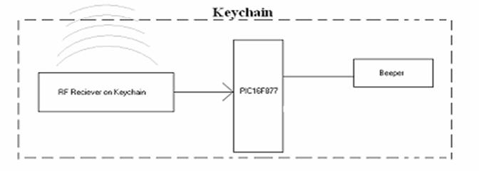

Figure 2: Block Diagram of the Keychain System
The overall system functions as specified: The main system microcontroller receives an input from the temperature sensors. The microcontroller then responds accordingly. At temperatures below 45 or above 80 degrees Fahrenheit, the microcontroller sends out a high signal to the transmitter, which in turn sends the signal to the key chain system. The microcontroller also activates the vehicles panic alarm and unlocks the doors while in that temperature range. The keychain system then receives the high signal sent from the main system and the beeper will activate. The main system continually checks the temperature.
The project was broken down into a set of 5 subprojects which were completed independently and then integrated.
Temperature Sensor Circuit
Three temperature sensors were desired in the design to give accurate values and input the average temperature into the main microcontroller.
Main Microcontroller
A microcontroller was needed to read in values from the temperature averaging circuit and also output the appropriate values to the panic alarm system and transmitter.
Keychain Microcontroller
This microcontroller was needed to read in the appropriate value from the receiver and send a signal to the buzzer.
Receiver/ Transmitter Circuit
A transmitter was needed to take in a signal from the main microcontroller and send the same signal to the receiver on the keychain system with minimal static and making sure correct frequencies were being transmitted.
Voltage Regulating Circuit
A 9V battery was used and an appropriate voltage reducing circuit was needed to bring the voltage level down to 5V so all appropriate components in the system could run.
2. DESIGN PROCEDURE
2.1 Design Decisions
2.1.1 Temperature Sensor Circuit
The temperature sensors used in this product were the TMP36 from Analog Devices. These were the most cost efficient sensors available that operate from -10 to 110 degrees Celsius, and that also output accurate values in that range. The temperature sensor outputs a voltage which corresponds to the temperature. It outputs approximately 10mV per 1 degree Fahrenheit. Due to different temperatures that each sensor might output through sunlight or shady areas on the car seat, multiple sensors are located on it. The outputs of the sensors are averaged, through an averaging circuit, which essentially puts the outputted values in parallel and sends them through an op-amp. The purpose of the op-amp is to provide a feedback loop in order to eliminate the load that may be created by the PIC16F877 microcontroller. The value outputted by the averaging circuit is used to control the activation of alarms by the microcontroller. An alternative to this method would have been to input the three temperature sensor voltages to the microcontroller directly and let it do the averaging. This alternative would have helped guard against temperature sensor failures by only using valid readings in the average. This alternative was not implemented, because it was not thought of until now.
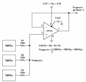
Figure 3: Temperature averaging circuit
2.1.2 Main Microcontroller
The PIC16F877 microcontroller was chosen mainly because it could be programmed in C language. Although none of the group members knew the C language, it was figured the language would be easier to comprehend due to their previous Java experience. Also, with some guidance from the TA, it was learned that using this microcontroller would eliminate the need for a separate RS232 device because it is a built in feature. Another feature that was needed was an Analog to Digital converter for the temperature sensor input. This was also conveniently built into the microcontroller. For these reasons PIC16F877 was the ideal choice for the project.
2.1.3 Keychain Microcontroller
The keychain microcontroller is the same PIC16F877 that was used in the main PCB. The reasons to use this microcontroller are that it is programmed in the C language and it has an integrated RS232 feature. Additionally, this microcontroller was chosen because very light code was needed for the project; therefore a heavy duty processor was not needed.
2.1.4 Receiver/Transmitter Choices
For the receiver and transmitters that were needed, the HP-2 series from Linx Technologies were fairly simple to use and required no previous knowledge of RF technology. Thus, they were the best choice for this product. Not only were they readily available from the lab, but they had very simple connections, which required only Vcc, Gnd, and a signal to transmit/receive. They were 900MHz components and largely satisfied the distance range required for the keychain. Another possibility that could have been utilized was the use of the newer HP-3 series products. These new modules were enclosed in a casing and therefore caused less static interruption. However, using the newer models would have led to a less cost efficient product.
2.1.5 Voltage Reducing Options
In order to get the required 5V to all of the system components, it was decided that a 9V battery would be used and its would have to be voltage regulated. The original design utilized a voltage divider circuit, which would have given 5V from the 9V battery. However, this design would not have achieved the goal of the product. Since the goal was to create an energy efficient car seat, having power constantly being consumed through the resistors of a voltage divider did not make sense. Instead the MC7805 5V voltage regulator was used. This was a more efficient option and also achieved project goals. Another factor to consider was where to place the regulating circuit, either before or after the buckle switch. Originally this was not considered, but it was realized that the regulating circuit had to come after the switch so it too did not consume power when not being used.
3.0 DESIGN DETAILS
3.1 Power Supply and Buckle
The main system is supplied power through a 9V battery. However, the components require 5V to operate efficiently. Thus, a 5V voltage regulator is required. In order to save battery life, a buckle switch on the car seat was implemented. Hence, the main system will only be powered when the buckle is fastened. In this situation, the voltage regulator will be supplying the components with 5V, which allows the system to operate. However, if the buckle is unfastened, there will be no voltage supplied from the 9V battery to the voltage regulator. Thus, the system will not be in operation and the battery life will be conserved. The circuit diagram for this portion of the product can be seen below in Figure 4.
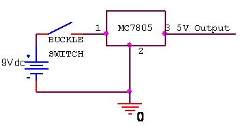
Figure 4: Power supply and buckle switch circuit
3.2 Temperature Sensors
There are three temperature sensors located on the car seat. These are shown in Figure 5. The temperature sensors used in this product were the TMP36 from Analog Devices. These were the most cost efficient sensors available that operate from -10 to 110 degrees Celsius, and output accurate values in that range. The temperature sensor outputs a voltage which corresponds to the temperature. It outputs approximately 10mV per 1 degree Fahrenheit. The outputs of the sensors are averaged, through an averaging circuit, which essentially puts the outputted values in parallel and sends them through an op-amp. The purpose of the op-amp is to provide a feedback loop in order to eliminate the load that may be created by the PIC16F877 microcontroller. The averaging circuit can be seen in Figure 6.
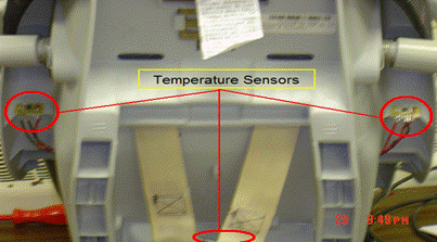
Figure 5: Location of temperature sensors on car seat
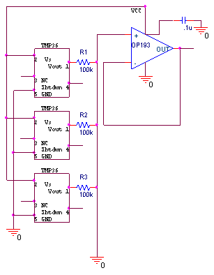
Figure 6: Temperature averaging circuit
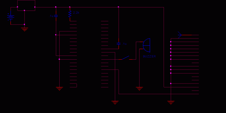
3.3 Main Microcontroller and Peripherals
The main microcontroller continually receives an input signal from the temperature averaging circuit. The microcontroller then acts according to the code provided in Appendix A. At temperatures below 45 or above 80 degrees Fahrenheit, the microcontroller sends out a high signal to the transmitter, which in turn sends the signal to the key chain system. The keyless entry system, which controls the function of unlocking the doors and setting off the panic alarm, is triggered when supplied 5V. Once triggered, the panic alarm can be easily turned off by use of a toggle switch, which is located on the car seat. Thus, the microcontroller activates the keyless entry system by outputting a high voltage at temperatures below 45 or above 80 degrees Fahrenheit and a low voltage otherwise. This can be seen in Figure 7 below.
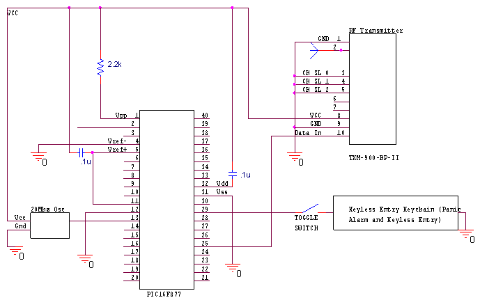
Figure 7: Main System Schematic
3.4 Keychain Microcontroller and Peripherals
The keychain microcontroller continually receives input from the receiver. It processes the signal according to the code in Appendix B. At temperatures below 45 or above 80 degrees Fahrenheit, the receiver receives a high signal from the transmitter, and in turn sends the signal to the key chain microcontroller. Thus, the microcontroller activates the beeper by outputting a high voltage at temperatures below 45 or above 80 degrees Fahrenheit and a low voltage otherwise. Once activated, the beeper can be easily turned off by use of a toggle switch which is located on the keychain. This can be seen in Figure 8 below.
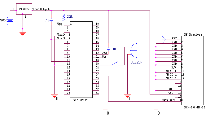
Figure 8: Keychain System Schematic
4. DESIGN VERIFICATION
4.1 Testing
Several tests were conducted on the car seat to test its functionality. Every component was tested individually and then integrated into the entire system and tested on a higher level.
Power Supply
The battery was measured by a multimeter to ensure that it was indeed 9V. Then the voltage regulator was also tested by using the multimeter to verify an output of 5V. The Agilent Triple Output DC Power Supply was used to simulate an input from the battery at different voltages greater than 5V and less than 9V. This test showed that the voltage regulator would still output 5V at the different input voltages.
Buckle Switch
The buckle switch is a push-button switch that was tested by fastening the seatbelt and measuring the electrical connection across the switch through an LED. When the buckle was fastened, the LED was on, indicating power to the system. When the buckle was not fastened, the LED was not on, indicating there was no power to the system. Also, child-like movements were simulated in the car seat and verified the buckle switch would not become loose or break.
Temperature Sensor
Each of the three temperature sensors were tested to ensure proper functionality by using a multimeter to measure the voltage outputted at various temperatures. Different methods were used to replicate hot and cold environments. A blow dryer was used as a heat source while a can of compressed air and a can of circuit chiller were used as separate cooling sources. The data collected is shown below in Table 1.
Table 1:
|
Temperature Source |
|
|
Hair Dryer (after 20s) |
.829V - 1.109V |
|
Circuit Chiller (after 3s each sensor) |
.128V - .344V |
|
Compressed Air (after 5s each sensor) |
.224V - .438V |
Main Microcontroller, Keychain Microcontroller and Peripherals
The main microcontroller was tested by imitating the temperature sensor values through the Agilent Triple Output DC Power Supply. This was done by connecting the power supply to pin 2 on the PIC16F877. The range of values tested was from 0V to 1.5V. The limits in the test were .8V and .39 V. The function of the main microcontroller is to output high signals to the transmitter and keyless entry when simulated temperature sensor values are less than .39V or greater than .8V, and to output low signals otherwise. When the keyless entry is activated, a red LED on the device will blink indicating that the panic alarm has been set off and the doors have been unlocked. The keychain microcontroller receives the signal from the receiver and outputs a high signal at pin 29 (keychain microcontroller and beeper) to the beeper when simulated temperature sensor values are less than .39V or greater than .8V, and to output low signals otherwise. These functions were tested by an oscilloscope at pin 25 (transmitter) and pin 26 (receiver). In addition to the oscilloscope, a multimeter was used at pin 30 (main microcontroller and keyless entry). The expected high (5V) and low (0V) outputs were seen at the different temperatures.
Table 2: Output at Keyless entry caused by Simulated Temperature Sensor Input
|
Simulated Temperature Sensor Input |
Output at Pin 30 (Main Microcontroller and Keyless Entry) |
Keyless Entry LED |
Output at Pin 29 (Keychain Microcontroller and Beeper) |
Beeper Alarm (on/off) |
|
0V |
4.93V |
On |
4.93V |
On |
|
.1V |
4.93V |
On |
4.93V |
On |
|
.25V |
4.93V |
On |
4.93V |
On |
|
.3V |
4.93V |
On |
4.93V |
On |
|
.39V |
4.93V |
On |
4.93V |
On |
|
.42V |
.014V |
Off |
.014V |
Off |
|
.5V |
.014V |
Off |
.014V |
Off |
|
.6V |
.014V |
Off |
.014V |
Off |
|
.7V |
.014V |
Off |
.014V |
Off |
|
.8V |
4.93V |
On |
4.93V |
On |
|
.9V |
4.93V |
On |
4.93V |
On |
|
1.0V |
4.93V |
On |
4.93V |
On |
|
1.1V |
4.93V |
On |
4.93V |
On |
|
1.2V |
4.93V |
On |
4.93V |
On |
|
1.3V |
4.93V |
On |
4.93V |
On |
|
1.5V |
4.93V |
On |
4.93V |
On |
Table 3: Output at Transmitter caused by Simulated Temperature Sensor Input
|
Simulated Temperature Sensor Input |
Output at Pin 25 (Transmitter) |
Output at Pin 26 (Receiver) |
|
0V |
4.81kHz |
4.81kHz |
|
.1V |
4.81kHz |
4.81kHz |
|
.25V |
4.81kHz |
4.81kHz |
|
.3V |
4.81kHz |
4.81kHz |
|
.39V |
4.81kHz |
4.81kHz |
|
.42V |
1.92kHz |
1.92kHz |
|
.5V |
1.92kHz |
1.92kHz |
|
.6V |
1.92kHz |
1.92kHz |
|
.7V |
1.92kHz |
1.92kHz |
|
.8V |
4.81kHz |
4.81kHz |
|
.9V |
4.81kHz |
4.81kHz |
|
1.0V |
4.81kHz |
4.81kHz |
|
1.1V |
4.81kHz |
4.81kHz |
|
1.2V |
4.81kHz |
4.81kHz |
|
1.3V |
4.81kHz |
4.81kHz |
|
1.5V |
4.81kHz |
4.81kHz |
Transmitter and Receiver
The transmitter and receiver modules were tested by using the oscilloscope to view the waveform and frequency of the signal being transmitted and received. Figure 6 shows the signal being transmitted by the main system and Figure 7 depicts the signal being received by the keychain system. The key points to notice in both figures are the similar frequency rate and shape of the waveforms.
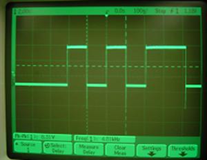
Figure 9: The signal being transmitted
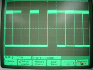
Figure 10: The signal being received
4.2 Conclusions
The testing of the various system components generated the expected results. The tests performed in the danger zone (below 45 or above 80 degrees Fahrenheit) produced all the desired functions as specified above, allowing the product to be marketable. The system also performed well in the safe zone (between 45 and 80 degrees Fahrenheit), by not activating any alarms and continuously checking the temperatures.
5. COST
5.1 Parts
Table 4: Parts list and cost
|
Part |
Number of Parts |
Price per Part |
Total Price |
|
TMP36 (temperature sensor) |
3 |
$0.40 |
$1.20 |
|
TXM-900-HP-II transmitter |
1 |
$6.90 |
$6.90 |
|
RXM-900-HP-II receiver |
1 |
$6.90 |
$6.90 |
|
PIC16F877 |
2 |
$6.00 |
$12.00 |
|
OP193 op amp |
1 |
$1.12 |
$1.12 |
|
Keyless Entry Car System (CSI-300) |
1 |
$90.00 |
$90.00 |
|
7805C 5V Voltage Regulator |
2 |
$1.29 |
$2.58 |
|
Buzzer |
1 |
$.90 |
$.90 |
|
Resistors |
5 |
$.29 |
$1.45 |
|
Car Seat |
1 |
$40.00 |
$40.00 |
|
Fox 20MHz Crystal Clock Oscillators |
2 |
$1.40 |
$2.80 |
|
.1 uf Capacitor |
5 |
$.69 |
$3.45 |
|
9V Lithium |
2 |
$2.50 |
$5.00 |
|
Push Button Switch |
2 |
$0.55 |
$1.10 |
|
22 uf Capacitor |
1 |
$.69 |
$.69 |
|
8-pin surfboard |
4 |
$4.12 |
$16.48 |
|
IC Boards |
2 |
$6.00 |
$12.00 |
|
Parts Grand Total |
$204.57 |
||
5.2 Labor
Table 5: Labor Cost
|
Labor | |
|
Salary |
$30/hr |
|
Total Hours Per Person |
35 |
|
Number of Employees |
3 |
|
Overhead Multiplier |
2.5 |
|
Total Cost of Labor |
$7,875 |
5.3 Total Cost
Labor Cost + Parts Cost = $7,875 +$204.57 = $8079.57
6. CONCLUSIONS
6.1 Accomplishments
This smart car seat fulfilled all of the projected goals including:
6.2 Recommendations
Recommendations for future improvements include having a smaller and more compact keychain. Additionally, having a design that has the maximum distance between the crystal clock oscillator and the microcontroller will allow for less interference of the signal being transmitted or received. Also, to future groups using the HP2 series Rx/Tx, be sure the correct turn-on sequence is known. This can cause the entire circuit to not function.
Smart Car Seat Code ///
written by Payal Dhalgara, Sagar Patel and Sandra Yu ///
#include '16F877.h'
//#include <math.h>
#include <stdio.h>
#fuses Hs, NOWDT, NOPROTECT, NOLVP
#use delay (clock=20000000)
//Tx is connected on Pin 25
//Rx is connected on Pin 26
#use rs232(baud=9600, xmit=PIN_C6, rcv=PIN_C7, bits=8)
//#use standard_io(D)
#use fast_io(A)
#use fast_io(C)
#use fast_io(D)
//define pins on PIC
#define MY_TRISD 0b00000000 //one input, the rest outputs
#define MY_TRISA 0b00000001 //one input, the rest outputs
#define MY_TRISC 0b00000000
#define Doors_unlock PIN_D6 //pin29
#define Panic_alarm PIN_D7 //pin30
//pin25
int8 TempSense;
//function prototypes
void initADC(void)
void readADC( void)
void main()
else if (TempSense < 20) //Temperature is less than or equal to 45 degrees F. TOO COLD!!
else //do nothing, temp is OK
}
Smart Car Seat Code: Keychain ///
written by Payal Dhalgara, Sagar Patel and Sandra Yu ///
#include '16F877.h'
//#include <math.h>
#include <stdio.h>
#fuses Hs, NOWDT, NOPROTECT, NOLVP
#use delay (clock=20000000)
//Tx is connected on Pin 25
//Rx is connected on Pin 26
#use rs232(baud=9600, xmit=PIN_C6, rcv=PIN_C7, bits=8)
//#use standard_io(D)
#use fast_io(A)
#use fast_io(C)
#use fast_io(D)
//define pins on PIC
#define MY_TRISD 0b00000000 // All outputs
#define MY_TRISA 0b00000000
#define MY_TRISC 0b10000000
//one input, the rest outputs
#define buzzer PIN_D6 //pin29
int8 signal; //pin2
/*void initADC(void)
/*void readADC( void)
void main()
else
}
REFERENCES
MANUALS
[1] Custom Computer Services Incorporated, CCompiler Reference Manual, Custom Computer Services Incorporated, 1994.
|
Politica de confidentialitate | Termeni si conditii de utilizare |

Vizualizari: 1304
Importanta: ![]()
Termeni si conditii de utilizare | Contact
© SCRIGROUP 2026 . All rights reserved