| CATEGORII DOCUMENTE |
| Bulgara | Ceha slovaca | Croata | Engleza | Estona | Finlandeza | Franceza |
| Germana | Italiana | Letona | Lituaniana | Maghiara | Olandeza | Poloneza |
| Sarba | Slovena | Spaniola | Suedeza | Turca | Ucraineana |
THE JOINTS OF WOOD ELEMENT
Cutting-edge joints
1. General elements
1.1. Cutting-edge joints transmit the efforts from one piece to another directly on the contact surface.
1.2. These types of joints are characterised by great deformations in first phase of joining till obtaining a direct contact between the joining surfaces (the second phase in characterised by small deformations).
1.3. The pieces of a such joint are fixed with bolts or clamp to mentain the surface contact and to not allow the relative displacement between pices. In joint designing one should take into account the gross-area of joining timber pieces but not the efforts that joining pieces may carry.
2. Prolongation cutting-edge joint
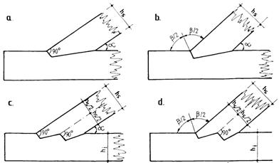
2.1. The details for joining two compressed timber pieces should fulfil the dates in figure 8.8.
2.2. There are not allowed non-symetrical cutting-edge joints.
2.3.
The checking of strength capacity is apriori satisfied (![]() ).
).
2.4. The tights with paddles are checked in flexure.
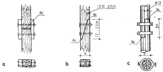
Figure 8.8. Prolongation cutting-edges joints with:
a) exterior plates; b) bolts; c) paddles
8.3.3. Cutting-edge joints of two timber elements placed normally
8.3.3.1. The normal cutting-edge joints are used to connect the beams with columns, the under-beam of plane trusses with wall purlin a.o. (see figure 8.9.).
8.3.3.2. In order to assures the stability to lateral displacement the joint must be design with tenon (figure 8.9, a, c and e) or clamps (figure 8.9, b and f). The depth of the space is greater with 510 mm than the height of tenon in order to transmit the effort to contact surface.
8.3.3.3. The efforts on contact suface is made through normal crushing on fibers at beam, underbeam, wall purlin and along the fibers at columns and posts. The tenon suface will decrease the surface contact in designing of such joints.
8.3.3.4. If circular timber is used the the cutting-edge of beam is oblique (see figure 8.9, c and d).

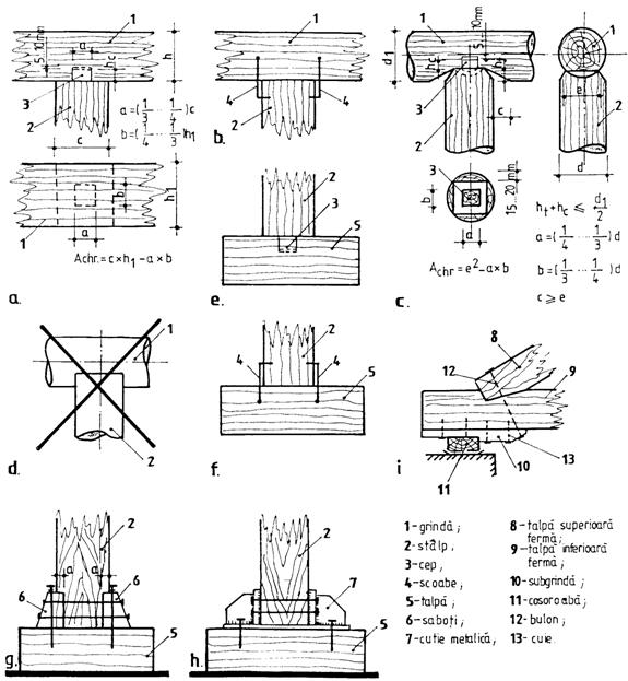
Figure 8.9. Simple cross-section bars subjected to axial compression normal to grains:
1 beam; 2 column; 3 tenon; 4 clamps; 5 base plate; 6 chock;
7 metalic box; 8 top-chord of plane truss; 9 bottom chords of plane truss;
10 underbeam; 11 wall purlin; 12 bolt; 13 nails.
8.3.3.5. Strength capacity of cutting-edge joints of two timber elements placed normal to each other is established with relationship (see paragraph 6.4):
![]() ,
(6.5)
,
(6.5)
where the terms are detailed in paragraph 6.4.
8.3.3.6. In joining posts on base plates higher resistance timber can be used if Qri < Qpost ef. Another solution is increasing the contact area with supplementary chocks (see figure 8.9, g) or metalic boxes (see figure 8.9, h). The chocks are displaced against lateral displacement using bolts thus the efforts are transmited by crushing surfaces.
8.3.4. Cutting-edge joints of two timber elements placed under an angle a
8.3.4.1. Detailing
The cutting-edges joints can be made with one or two sills function of efforts and the dimensions of joining elements.
The cutting of sills can be made:
- normal to compressed timber element, at an angles a < 30 (see figure 8.10, a and c);
- at bisectrice of exterior angle made by the two elements, at angles a³30 (figure 8.10, b and d).
|
|
Figure 8.10. Cutting-edge posibilities of simple sill (a and b) and double sill (c and d) |
In designing joints with simple sill one should take into account the following (see figure 8.11, a):
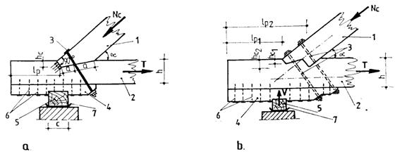
Fig. 8.11. Cutting-edge joints:
a with simple sill; b with double sill;
1 top chord of truss; 2 bottom chord of truss; 3 safety bolts;
4 underbeam; 5 wall purlin; 6 nails; 7 water insulator material
the height of sill (cutting depth) hc should be minimum 2 cm for processed timber beams, 3 cm for circular beams and maximum h/3 at supports, respectivly h/4 at intermediary joints of trusses or for timber elements with a width smaller than 8 cm;
the length of sill, lp should be: lp³10 hc ; lp³ 2h ; lp³20 cm;
in shear designing the length of sill should be: lf£10hc; lf£ 2h;
safety bolts are normal to top chord for a < 30 , normal to cutting for a ³ 30 and are displaced in the middle of cutting;
the underbeam will be detailed such as the safety bolts will pass symetrically for cutting;
the minimum diameter for bolts are l/25 and at least 12 mm.
In designing joints with double sill one should take into account the following (see figure 8.11, b):
the height of 1st sill, hc1, must be minimum 2 cm for processed beams and 3 cm for circular cross-section beams;
the height of 2nd sill, hc2, should be at least 2 cm higher than hc1 and superior limited at 1/3 of the beam height at supports joints of trusses, respectivly h/4 at intermediary joints or for timber elements with a width smaller than 8 cm;
the length of sills lp1 and lp2 should be lp1³ 10 hc1; lp1³2h; lp2³ 10 hc2;
in shear designing the lengths of sills should be: lf1£10 hc1; lf1£ 2h; lf2£ 10 hc2;
there are necessarily safety bolts and under-beam for angles a £ 45 ; in this case the same conditions as for simple sill shold be fulfilled;
it is recomanded that centring of joint should be made in the longitudinal axis of top-chord.
Designing
a The shear capacity under the angle a of a cutting-end joint with simple sill is established with relation:
![]() ,
(8.1)
,
(8.1)
where: ![]() strength capacity of parallel crushed area,
parallel to grains, in N, established with relation:
strength capacity of parallel crushed area,
parallel to grains, in N, established with relation:
![]() (8.2)
(8.2)
Qr - strength capacity of normal crushed area, normal to grains, in N, established with relation:
![]() ; (8.3)
; (8.3)
where a is the angle between sill and direction of grains of the element which is crushed;
![]() si
si ![]() - strength resistances of masif wood to
compression parallel and respectively normal to grains function of wood
species, quality class and exploitation conditions, in N/mm2;
- strength resistances of masif wood to
compression parallel and respectively normal to grains function of wood
species, quality class and exploitation conditions, in N/mm2;
Ap - projection of sill surface on parallel direction with the grains of the element which is crushed, in mm2;
Ap - projection of sill surface on normal direction with the grains of the element which is crushed, in mm2;
mr support coefficient with value 1,60, according to specifications given in paragraph 6.4.
b - The shear capacity under the angle a of a cutting-end joint with double sill is established by summing the capacity of each sill, determined with relation (8.1):
![]() (8.4)
(8.4)
c The shear capacity of a simple sill is established with relation:
![]() , (8.5)
, (8.5)
where: ![]() is the design shear strength parallel to
grains established function of wood species characteristic strength to shear
parallel to grains, quality class of wood and exploitation conditions,
expressed in N/mm2 (table 6.1);
is the design shear strength parallel to
grains established function of wood species characteristic strength to shear
parallel to grains, quality class of wood and exploitation conditions,
expressed in N/mm2 (table 6.1);
Af
is the sheared area of the sill in mm2 ![]() ;
;
mT - treatment coefficient of wood;
![]() where: b is a
coefficient with values: 0,25 for unilateral shear and 0,125 for bilateral
shear;
where: b is a
coefficient with values: 0,25 for unilateral shear and 0,125 for bilateral
shear; ![]() - shear treshold length limited at 10xhch,
in mm; e eccentricity for shear with
respect to the treshold direction.
- shear treshold length limited at 10xhch,
in mm; e eccentricity for shear with
respect to the treshold direction.
d - The shear capacity of a double sill is established for each sill thus:
- for 1st sill:
![]() , (8.6)
, (8.6)
- for 2nd sill:
![]() , (8.7)
, (8.7)
where: ![]() ,
mT, mf1 si mf2 are the same as in
relation (8.5);
,
mT, mf1 si mf2 are the same as in
relation (8.5);
Af1 - is the sheared area
of 1st sill in mm2,![]() ;
;
Af2 - is the sheared area
of 2nd sill in mm2 ![]() .
.
e The effective shear forces in sills are established as projections of shear forces on sill directions, thus:
for simple sill, with relation:
![]() (8.8)
(8.8)
for double sill, with relations:
c for 1st sill:
![]() (8.9)
(8.9)
c for 2nd sill with relation:
![]() , (8.10)
, (8.10)
where:
Nc ef effective effort which act normal to sill;
Nc ef 1 effective effort for 1st sill which act normal to sill:
![]() ; (8.11)
; (8.11)
a - angle between the two timber elements;
As1 crushing area of 1st sill, in mm2;
As2 crushing area of 2nd sill, in mm2;
f The tensile capacity of bottom chord of a truss is established with relation (6.3) for centrically applied effort (the joint is axed through weight center of the cross section, figure 8.12, a) and with relation (6.13) for eccentrically applied effort (the joint is axed through weight center of the gross cross section, figure 8.12, b.
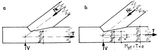
Figure 8.12. Joint centring by weight center axis of cross-section (a) and
of gross cross-section (b)
g The checkings of safety bolts:
![]() ,
(8.12)
,
(8.12)
where:
Nef bolt is the axial effort in bolts, determined with relation:
![]() ; (8.13)
; (8.13)
![]() - the bolt
capacity to tension, established with relation:
- the bolt
capacity to tension, established with relation:
![]() , (8.14)
, (8.14)
Nc axial compression effort from joint, in N;
a - angle between timber elements;
Anet gross area of safety bolt, in mm2;
Rot strength resistance of metal to tension, in N/mm2;
m0 bolt working coefficient having the value 0 (takes into account the dinamic action).
nb number of bolts.
h The checking of contact surface between under-beam and wall purlin is made with relation:
![]() , (8.15)
, (8.15)
where:
Vef is the vertical reaction in support joint, in N;
Qri strength capacity to shear normal to grains of contact surface between underbeam and wall purlin, established with relation (6.5).
i The number of nails, n, necessary for joining the underbeam with wall purlin is determined with relation:
![]() ,
(8.16)
,
(8.16)
where:
L is horizontal component of effort from bolt, in N, established with relation:
![]() (8.17)
(8.17)
La minimum capacity of a
cylindrical rod, in N, established with relation ![]()
Dictionary
base plate = talpa
chock = sabot
clamp = scoaba
paddle = zbant
sill = prag
tenon = cep
wall purlin = cosoroaba
|
Politica de confidentialitate | Termeni si conditii de utilizare |

Vizualizari: 1691
Importanta: ![]()
Termeni si conditii de utilizare | Contact
© SCRIGROUP 2026 . All rights reserved