| CATEGORII DOCUMENTE |
| Bulgara | Ceha slovaca | Croata | Engleza | Estona | Finlandeza | Franceza |
| Germana | Italiana | Letona | Lituaniana | Maghiara | Olandeza | Poloneza |
| Sarba | Slovena | Spaniola | Suedeza | Turca | Ucraineana |
Gas metering station control and fiscal system
Abstract Natural gas distribution system, using closed loop control methods, with redundant gas metering stations, each monitoring the quantity and quality of gas. Local controlled processes include gas quality determinations, gas flow and pressure measurement and regulation, filtering and overcompensation and most important fiscal metering. The basic philosophy for the fiscal measurement is to have a separate system for fiscal in order to segregate the data (fiscal data from process data). Controlling and watching the fiscal measurement by Metering Station Fiscal System (include the fiscal data transmission) is separated by the controlling and watching the process by Metering Station Control System (include the process data transmission).
Introduction
The gas distribution networks have been using local/manual control of the pipe lines to oversee the fiscal metering process and safety standards. For this purpose, a 3-shift operation for each metering point was organized in order to keep under control the process.
The fiscal metering was made using tachometers that recorded on calibrated paper, information regarding flow rate on fixed volume, recorded data that was later used for manual calculation over a period of time. This offline metering process does not provide data compatible with centralized networking requirements.
2 System description; Architecture
A new control and fiscal system were designed, to segregate the data (fiscal and process). Control and monitoring of the fiscal measurement is done in an automatic fashion by the Metering Station Fiscal System. The Control System manage the process, monitors and controls the gas metering station, signal inappropriate operating conditions and supports remote-control operations.
 The Metering Station Fiscal System and the Control System satisfy the
centralized networking requirements, the recording of data, centralized
monitoring measurement, control and data transmission.
The Metering Station Fiscal System and the Control System satisfy the
centralized networking requirements, the recording of data, centralized
monitoring measurement, control and data transmission.
2.1 The metering station fiscal system
The Fiscal System has 2 different parts:
the metering devices (installed in the technologic container)
the electronic equipment (installed in the instrumentation container)
The fiscal metering devices consist of 2 parallel meter runs of 600mm, which each are equipped with a turbine gas meter (TGM) and sensors for pressure and temperature. All meter are connected by gas collector to ensure the same hydraulic conditions for every meter run.The control metering installation consists of an ultrasonic gas meter, pressure and temperature sensors. In order to adapt to the supply situation from time to time, the load of the individual meter runs is monitored continuously by a control and regulating system and meter runs are switched on or off as required automatically. The meter is operated between minimum and maximum (90%) flow rate. In order to harmonize the recording of fiscal data, volume converters and gas chromatographs are equipped with a serial interface pursuant to DVGW G485 'Digital interface for gas metering devices' (DSfG interface). All thus equipped gas meters are connected to a measurement recorder via the DSfG data bus. Remote reading of the measurements is possible via GSM, a DSfG data connection is hooked up to the DSfG data bus.
The electronic equipment consist of flow computers with digital measurement recorder and fiscal data transmission via GSM. Flow Computers conform to EN 12405, and corrections of the high-pressure error curve are made. Flow computers have a DSfG interface for the transfer of fiscal and control data and additionally are able to set up a completely independent data channel to communicate with the control system through gateway. Online values of the gas composition from the gas chromatograph are available via the DSfG interface.
2.2 The metering station control system
The metering station control system is an automation control system that monitors and controls the gas metering station, signals inappropriate operating conditions and supports remote-control operations. The Metering Station Control System satisfies the centralized networking requirements, centralized monitoring operations and local operations with process and parameters data transmission. The system insures also recording, processing, data displaying, data transmission.
The process control system has the following features and characteristics:
built as an open and distributed system
high degree of availability;
complying to the international and Romanian standards;
object-orientated system, centralized planning and parameters;
unauthorized access protection; user friendly interface software;
network management system.
The Metering Station Control System includes the following functions:
communication with gas chromatograph and monitor water dew point;
process data administration and transmission;
administration of the relational data base;
securing/archiving all process digital and analogue data with easy access searching and reading mode;
centralized programming function;
information functions, reports; alarm reports
centralized control process monitoring by recording, processing and displaying all of the process variables;
storing data in short-and long term archives, evaluation in the form of reports and graphics;
operation logging;
The ESD function
3 Process description
The gas metering
stations are located throughout
The metering stations can be operated in three different operating modes:
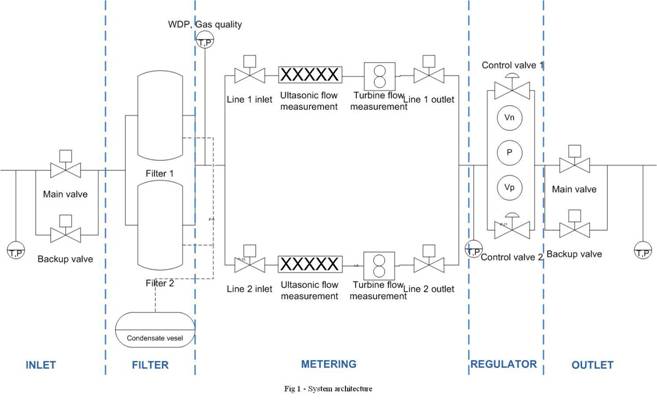
3.1. Inlet
After take off from the main pipe there is an insulation flange, to electrical insulate the metering station from the main pipe. In the inlet line, there is a hydraulically operated open/close valve. The purpose of this valve is to quickly take the metering station out of service in case of an emergency (ESD). The inlet temperature, the inlet pressure and the pressure across the open/close valve are measured.
During start-up the metering station can be pressure less.
3.2. Filter separator
The filter/separator module is located directly after the inlet module and before the metering module. There are two filter/separators. One is in operation, the other one is back-up. Each filter has two stages. The purpose is to clean the gas from particles and hydrocarbon liquids (the gas is dry, no water present).
The filters are, during normal operation, pressurized together with the inlet module. All hand valves must be opened at start-up. The hand valves have no control have no control system interaction. When the hand valves of the filter separator are closed, the inlet module is pressurized. Across each filter there is a pressure difference transmitter, if the filter is in operation the pressure drop is between 0.15 and 0.5 bar. The control system can generate alarms to indicate that it is time to change the filter separator.
3.3. Gas metering
The purpose of the metering module is to measure the quality and the quantity of the gas. The metering module is placed directly after the filter/separator module and before the flow control module.
Each station has 2 or 3 metering lines: Either 1 or 2 main metering lines and always 1 backup redundant line. If a station has 2 metering lines, then each line has a 100% capacity. If a station has 3 metering lines, each line has 50% capacity.
The sample take off for the gas chromatograph is located at the inlet of the metering module. After the gas chromatograph water dew point, inlet pressure and temperature are measured. The line is then split into either 2 or 3 lines. Each metering line has a motor operated valve at the beginning and end of the line.
After the inlet valve of the gas metering module, a strainer is located which provides measurement of the differential pressure. If the differential pressure over the strainer becomes grater than a set value, then an alarm is generated and the back-up metering line will automatically be started.
After the strainer, ultrasonic and turbine flow meters are placed, each with its own temperature and pressure measurement, for fiscal purposes. When the flow rates differ with more than a set value, the software application triggers an alarm.
3.4. Regulator
The regulator module is placed behind the metering module and before the outlet module. The function of the regulator module is to regulate the gas flow with protection for high pressure and high flows for each individual metering line.
The regulator module consists of 2 control valves with block valves in front and behind each control valve. During normal operation only one control valve is active, the other one being in stand-by (closed). On the inlet of the regulator module there is also a pressure transmitter.
In operation, when the outlet pressure is higher then the inlet pressure, the flow through the metering station must be stopped using the active control valve. The valve must be ramped to close. As long as the inlet pressure does not become higher then outlet pressure, the control valves are kept closed and locked in a mode that disables operator action.
The software application allows setting of a tuneable value for the maximum output of the PID controller.
3.5. Outlet
The outlet module is the last part of the metering station. After the outlet module, an insulation flange is passed connecting the station back to the main pipe, to electrically insulate the metering station from the main pipe. In the outlet line there is a hydraulic operated open/close valve. The purpose of this valve is to quickly take the metering station out of service in case of an emergency. The module also contains also pressure transmitters, temperature sensors and pressure measurement across the open/close valve. The hydraulically operated valve has a bypass circuit which consists of 2 ball valves with an electrically operated solenoid valve in between, in order to equalise pressure across the hydraulically operated valve before opening.
3.6. Automatic start-up & control
The station is able to start-up automatically when the operator gives the start command. Actions taken during automatic start-up:
Start inlet and outlet module; The inlet is pressurized up to the metering line inlet valves. The outlet line is pressurized up to the control valve.
To pressurize the line between the metering run and the control valve, the control valve is opened to a tuneable value and immediately closed again
Start metering line
Start regulator control
Start secondary metering line
3.7. Emergency Shut Down
An emergency shut down (ESD) can be initiated by hand switches, manual call points. When activated the ESD cuts the power using safety relays to the valves and motor of the hydraulic packages as well as to the magnetic bypass valves in the inlet and outlet module.
After ESD reset, the station shall come back in a state from which it cannot start straight after ESD reset. Station start will be an operator action.
4. Results
Aggregated output data from the gas metering station include gas quality
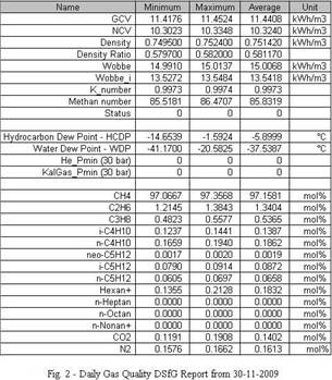
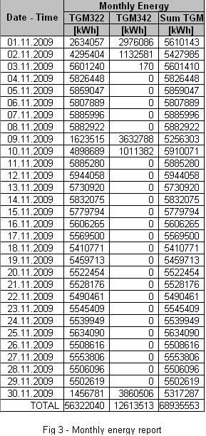
 flow information (quantitative information),
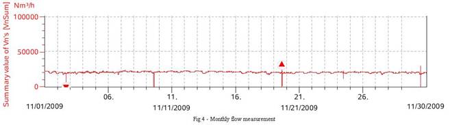
energy measurement (aggregated information of the equivalent of gas quality and
quantity) and are arranged in tables and charts.
flow information (quantitative information),
energy measurement (aggregated information of the equivalent of gas quality and
quantity) and are arranged in tables and charts.
5. Conclusions
The implementation of this system insurers online fiscal metering information, autonomous operation of the metering and distribution process that provide a human free operation of the distribution network.
The Metering Station control and fiscal systems increase the gas throughput, lower the loses caused by the unavailability of the distribution network, increase by a factor of 100 the MTBF and offer a high level of automation of the gas distribution system.
The Metering Station offers in a technologic container: filters and separators, metering section, regulating section, sampling points section, instrumentation section, diesel generator, condensation and storage tank.
The metering station control system is an automation control system that monitors and controls the gas metering station, signals inappropriate operating conditions and supports remote-control operations.
►The system offers the possibility of real-time monitoring of the gas quality and quantity, fiscal monitoring, error monitoring and automatic emergency shutdown procedures.
► The system was designed to work interconnected with other gas metering stations and also with central level processing hardware and software, allowing access to information, at different decisional levels.
References:
|
Politica de confidentialitate | Termeni si conditii de utilizare |

Vizualizari: 3146
Importanta: ![]()
Termeni si conditii de utilizare | Contact
© SCRIGROUP 2026 . All rights reserved