| CATEGORII DOCUMENTE |
| Bulgara | Ceha slovaca | Croata | Engleza | Estona | Finlandeza | Franceza |
| Germana | Italiana | Letona | Lituaniana | Maghiara | Olandeza | Poloneza |
| Sarba | Slovena | Spaniola | Suedeza | Turca | Ucraineana |
Microsofta Flight Simulator 2004:
A Century of
Flight
Software Development Kit
Aircraft Editor (FSEdit)
Installing and Starting FSEdit
Creating New Components from Scratch
Modifying and Deleting Default Aircraft
Creating New Aircraft from Templates
Adding or Deleting an Aircraft
To add an existing aircraft using FSEdit
To add a new aircraft using FSEdit
To delete an aircraft using FSEdit
To increase the viewing area of the gauge area
To resize the view of the panel
To copy and paste a gauge from another aircraft panel
To copy a gauge from the gauge area onto your panel
To increase the viewing area of the gauge area
To see how the gauge will look from within the cockpit
To listen to the existing sound, replace it, or remove it
Table 1: Reference Datum Properties
Table 2: Wing and Tail Geometry
Table 8: Empty Weight Parameters
Table 9: Moments of Inertia Parameters
Table 10: Piston Engine Properties
Table 11: Turbocharger Properties
Table 12: Engine Position Properties
Table 13: Turboprop Engine Properties
Table 14: Turboprop Engine Position Parameters
Table 15: Jet Engine Parameters
Table 16: Jet Engine Position Parameters
Table 17: Propeller Properties
Table 19: Gear and Scrape Points
Table 20: Static Geometrical Parameters
Table 21: Flight Control Effectiveness Tuning Parameters
Table 22: Stability Tuning Parameters
Table 23: Lift Tuning Parameters
The Aircraft Editor (FSEdit) in Microsoft Flight Simulator 2004 is a tool with a graphical user interface. You can use it to:
Modify, add, or delete aircraft.
Add, delete, or change aircraft panels, including gauges, instruments, and radios.
Change, play, or remove sound files.
Modify aircraft textures.
Alter flight dynamics.
To make the changes, FSEdit modifies the following files: Aircraft.cfg, Panel.cfg, and Sound.cfg.
To use this editor, you need basic knowledge of aircraft and aerodynamic terms and concepts. You may also need a Pilots Operating Handbook (POH) or similar reference material for the aircraft you want to modify, or you can use the default values provided by the editor.
By default, the following files were installed to your c:fs2004sdkfsedit_sdk directory:
readme.txt
eula.rtf
FSEdit.exe
FSEdit.exp
FSEDIT.HLP
FSEdit.lib
FSEditSDKFS2004.doc
Move (or copy) the following files to directory in which fs9.exe is installed (by default, it would be C:Program FilesMicrosoft GamesFlight Simulator 9).
FSEdit.exe
FSEdit.exp
FSEDIT.HLP
FSEdit.lib
Once you have placed these files in this directory, you can launch the editor by double-clicking the FSEdit.exe file.
This editor does not provide a visual model for your aircraft. To create a visual model, you must create a new 3-D model or edit an existing visual model with the gmax tool created by discreet and provided in Microsoft Flight Simulator 2004.
Basic guidelines
Basic information on FSEdit.
Adding or deleting an aircraft
Instructions on how to add or delete an aircraft.
Changing panels and gauges
Instructions on how to modify panels, gauges, instruments, and radios.
Replacing sound files
Instructions on how to delete, change, or add sound files.
Modifying textures
Instructions on how to modify the textures (graphics) on the exterior of
the aircraft.
Altering flight dynamics
Instructions on how to alter the flight dynamics.
Important! The information included in this SDK is not supported by Microsoft Product Support Services.
Introduction
With FSEdit you can add, delete, or modify the following parts of existing aircraft:
Panel
Replace and modify panel bitmaps representing panel backgrounds, or
add/delete individual gauges, instruments, and radios.
Sound
Delete .wav (sound files) and replace them with new .wav files.
Textures
Modify the textures (bitmaps) representing the exterior of the aircraft
(using Microsoft Paint or another graphics application).
Flight Dynamics
Alter the flight dynamics by modifying the aircraft geometry and/or tuning
scalars.
The .air file for each aircraft controls how the aircraft flies. You cannot modify the .air file directly, but some of the parameters from the .air file are incorporated into each aircrafts .cfg (configuration) file. Many of these .cfg parameters are modifiable in FSEdit. The changes you make in FSEdit alter the aircrafts .cfg file, which in turn creates new aerodynamic parameters in the .air file.
For more information about the aircraft configuration (Aircraft.cfg) file, see the Aircraft Container SDK. The aerodynamic parameters in the .air file can be modified only by using the FSEdit program, which contains an internal function that determines the aerodynamic coefficients based on the changes you make in FSEdit.
FSEdit is not a tool for creating new components of aircraft from scratch. To create new panels and/or gauges, or for more information on panels and gauges, see the Panels and Gauges SDK.
You can modify any aircraft except the Flight Simulator 2004 default (read-only) aircraft. You can, however, make a copy of read-only aircraft (using the Save Copy As command on the File menu), and then modify that copy. For example, if you want to customize the panel in the default Cessna Skylane 182S, you can use FSEdit to copy the default (read-only) Cessna Skylane 182S and give it a new name. Then you can modify the panel in this new Cessna.
You cannot delete the default (read-only) aircraft. You can delete only aircraft that you have added.
You can create a new aircraft based on a template of the type of aircraft you want to create. These templates, however, contain no visual model. To see your new aircraft from an exterior view, you need to create a visual model using the gmax tool from discreet, which is provided with Flight Simulator 2002 Professional Edition.
You can use FSEdit to modify add-on aircraft created for Flight Simulator 98 or later versions. Aircraft created for versions prior to Flight Simulator 98 must be converted. For more information, see Adding and Deleting Aircraft later in this document.
Remember the following tips as you modify aircraft:
There is no Undo command. To undo changes, exit FSEdit without saving the aircraft.
Be sure to save your work often. The Save command saves all the changes you have made in the current session.
The .cfg files (configuration files) referenced in this document are text files with a .cfg extension. You can view and edit them with any text editor such as Microsoft Notepad. They are located in the appropriate aircraft subfolders of the Flight Simulator 9Aircraft folder. These files should be modified-and only-with caution--by experienced developers, because changes could render aircraft inoperable.
There are two ways to add new aircraft to Flight Simulator 2004.
|
To add |
Use |
|
A new aircraft |
The New command (on the File menu), which creates aircraft templates to help you start the design process. |
|
Aircraft that are compatible with Combat Flight Simulator: World War II European Series, Flight Simulator 98 (or any newer version of Flight Simulator) |
FSEdit (These aircraft do not require conversion. FSEdit converts them for you). |
Note: Because of the large-scale changes that were made in the aircraft system, aircraft not compatible with Flight Simulator 98 or with the original Combat Flight Simulator are not directly supported in Flight Simulator 2004 or FSEdit 2004.
|
Name of folder affected by adding or deleting aircraft in FSEdit |
Location on your hard disk |
|
Aircraft |
C:Flight Simulator 9Aircraft |
Note For more information about configuration files, see the Aircraft Container SDK.
On the File menu, click Open.
Navigate to the location of the folder that contains the aircraft you want to add.
Click the aircraft folder (the one that contains Panel, Texture, Sound, and Model folders) for the aircraft you want to add, and then click OK.
The contents of the aircraft container are copied to the location where you installed Flight Simulator 2004. You can edit the aircraft contents and then take the new aircraft for a test flight in Flight Simulator 2004.
Note Make sure you select the aircrafts main folder. If you select a subfolder, the OK button will remain unavailable.
On the File menu, click New.
Select the aircraft template you want to start with (engine type is the most important feature to select).
Click OK.
In the Save Copy As dialog box, enter a new name for your aircraft or keep the suggested name.
Click OK.
A complete aircraft container is created for you, except for a visual model (you must create the visual model using the gmax tool from discreet, which is included with Flight Simulator 2004, or by using another compatible tool for editing 3-D models).
Open an aircraft you have modified or created. (You cannot use FSEdit to delete any of the default aircraft.)
In the left pane, select the aircraft title under the Aircraft folder.
Press the DELETE key, or on the Edit menu, choose Delete.
Note: You will see only the Save and Delete menu commands if you have made a copy of a default Flight Simulator 2004 aircraft, have made a new aircraft using a template, or are selecting an aircraft that is not read-only.
Save your work often.
This section provides information that helps you add unique identification properties to your aircraft. The following table lists the properties and how you can use them.
Menu item |
Description |
|
Title |
The title of your aircraft. This must be a unique name (it cannot be the same as any other name in the Aircraft folder for FS2004). FSEdit suggests a title when you create or copy an aircraft. |
|
Manufacturer |
The main category used to identify aircraft in the Select Aircraft dialog box within Flight Simulator 2004. You can use an existing manufacturer (e.g., Cessna, Bombardier, etc.), or you can create your own categories (these will be listed under unknown in the FS2004 folder). |
|
Type |
The Model that appears in the Flight Simulator 2004 Select Aircraft dialog box. |
|
Variation |
A brief description of the variation of this aircraft. You can use this field to help identify an aircraft that you have created from a copy of an existing aircraft. |
|
Description |
A description of the aircraft. Whatever you place here will be visible in the Select Aircraft dialog box in Flight Simulator 2004 when you select the aircraft. |
|
Performance Specs |
The design performance specifications. You can use these design performance properties, in addition to the description of your aircraft, for reference. |
You can also use FSEdit a to modify the ATC (air traffic control) properties for your aircraft. The ATC system in Flight Simulator 2004 references this information when communicating with your aircraft.
Menu item |
Description |
|
Airline |
A drop-down list of available airline callsigns used in the ATC system. The names supplied with FS2004 are fictional, but you can add the names of real-world or virtual airlines by entering an airline name. For the name you enter to be used as an airline name in Flight Simulator, the name must be listed as an airline in the ATC voicepacks. You must also give your aircraft a flight number using the Flight field below. For a list of airlines included with Flight Simulator 2004, see the ATC Voicepack SDK. |
|
ATC Type |
A drop-down list that identifies the available aircraft types you can use in Flight Simulator 2004. If the type of aircraft youre creating does not exist in the drop-down list, you can add it by typing in the box. As with the Airline field, the type you enter must be present in the ATC voicepacks in order for the ATC system to use it. If the type you enter is not found in the ATC voicepacks, the ATC system refers to your aircraft as Experimental. |
|
Model |
A drop-down list of aircraft model designations. The model you choose is appended to the ATC Type field when ATC gives traffic calls about your aircraft and when using flight following. |
|
Flight |
The flight number for your aircraft. If you do not assign a flight number, your aircraft will be identified using its civilian callsign. |
|
ID |
The identification number for the aircraft. ATC uses this identification number in civilian callsigns. |
|
Heavy |
A check box that indicates to the ATC system if this
aircraft is a heavy aircraft (i.e., in the |
You can use the Panel feature in FSEdit to change the gauges, instruments, and radios that appear on your aircrafts panel. The only restriction in adding a gauge is that your aircraft must be equipped to drive that gauge. For example, if you add an engine gauge to a glider, the gauge will not work.
Important Note: Some of the newer aircraft (Beech Baron and Boeing 747-400) contain gauges that are incompatible with FSEdit. For more information on how to modify gauges for these aircraft, see the Panels and Gauges SDK.
You cannot use FSEdit to create new panels or gauges. For information about creating panels or gauges, see the Panels and Gauges SDK.
|
Name of file affected by Panel modifications in FSEdit |
Location on your hard disk |
.cfg section (representing the various panels) |
Where to get more Panel and panel.cfg information |
|
Panel.cfg [name of bitmap].bmp |
C:Flight Simulator 9Aircraft C:Flight Simulator 9Aircraft[Name of aircraft]Panel{Name of bitmap].bmp |
[Window00] |
Panels and Gauges SDK Aircraft Container System SDK |
FSEdit does not include an Undo command. To undo changes, exit FSEdit without saving.
Note: After you add a gauge, you can use FSEdit to test its operation (see below).
The Aircraft folder contains a Panel folder. The Panel folder contains the aircrafts Main Panel plus one or more sub panels (such as Radio Stack, GPS, or Compass).
In the left pane of FSEdit, double-click the panel icon. The panel opens in the upper-right portion of the screen, and the gauge well opens in the lower right.
Note: The gauges are not listed in a particular order.
Click on a gauge in the bottom portion of the FSEdit window. The name (label) appears below the gauge.
Use the scroll bars at the bottom of the FSEdit window or use the arrow keys.
Move the horizontal and vertical window frames.
The View menu allows you to choose various views (resolutions). These resolutions enlarge or reduce the size of the panel view. Choosing Auto-Fit resizes the entire panel to fit in the size of the viewing area that you have chosen.
Click the View menu and choose the appropriate resolution.
Note Although all the gauges are stored in the Gauges folder (C:Flight Simulator 9Gauges), there is not a one-to-one correspondence between the gauges in the gauge area and the Gauges folder because one .gau file may contain more than one gauge.
To modify a Flight Simulator 2004 default (read-only) panel in FSEdit, you must first make a copy of that aircraft and then modify the copy.
Right-clicking a gauge in the right panel window displays the following menu choices.
|
Menu item |
Description |
|
Reset size |
Resets the size of the gauge to the last saved size |
|
Restore aspect ratio |
Restores correct gauge proportions prior to new panel edits |
|
Delete |
Deletes the selected gauge |
|
Copy |
Copies the selected gauge |
There are two ways to insert a gauge in an aircraft panel:
Copy and paste the gauge from another aircraft panel.
Drag the gauge from the gauge area onto the panel.
Select the aircraft from which you want to copy the panel.
Right-click the main panel and choose Copy on the shortcut menu.
Open the aircraft to which you want to paste the panel.
Click the Panel icon (not a subpanel), and on the Edit menu, click Paste.
Locate the gauge using the scroll bars or arrow keys.
Drag the gauge onto the panel and resize it if necessary.
|
To |
Do this |
|
Delete a gauge |
Click it and press the Delete key, or right-click the gauge and then click Delete. |
|
Resize a gauge |
Click it in the Main Panel view and use the handles to resize. |
|
Change a gauges location |
Drag the gauge to a location on the panel background in the Main Panel view. |
Click on a gauge in the gauge area. The name (label) appears below the gauge.
Move the horizontal and vertical window frames.
Use the selections in the View menu to change the resolution of your viewing area.
Click the View menu, and then click Auto-Fit.
Click the Test Aircraft icon on the toolbar.
If the gauge does not look right on the panel, you can change the panel background in FSEdit or resize the gauge.
To see the effects of a change in Flight Simulator 2004, you must reload the aircraft.
On the Aircraft menu in Flight Simulator, click Select Aircraft, and then choose another aircraft in the dialog box.
Choose the original aircraft again.
Remember to save your changes frequently and before you exit FSEdit.
Any changes to the gauge layout on the panel since the last save cause the aircrafts name and the panel name to appear in bold until the current changes to the aircraft are saved.
After you add a gauge to a panel, the gauge name appears at the bottom of the list in the [Windowxx] section of the Panel.cfg file for that aircraft.
You can use FSEdit remove, replace, or play a .wav file, but you cannot create a new sound event. Clicking the Sound icon in the left panel of FSEdit opens two lists in the right panel:
The Section list refers to the section parameter in the aircrafts Sound.cfg file. This list lets you set when youll hear the sound during flight.
The File Name list contains the names of the .wav (sound) files that you can replace.
|
Name of file affected by Sound modifications in FSEdit |
Location on your hard disk |
Where to get more information on Sound and the sound.cfg file |
|
sound.cfg |
C:Flight Simulator 9Aircraft |
The Sound.cfg file section in the Aircraft Container System SDK. |
Files with similar names may represent similar events or simultaneous events. For example, the files listed in the Combustionxx parameter may represent:
The engine sound on startup.
The engine sound while airborne.
A mix of two .wav files that play simultaneously for a layered effect.
In the left pane of FSEdit, click the Sound folder.
In the right pane, right-click a sound file and on the shortcut menu, choose Change Sound, Play Sound, or Remove Sound.
Note: The Change Sound and Remove Sound commands are not available for default (read-only) aircraft. For more information, see Modifying and Deleting Default Aircraft earlier in this document.
Use the Texture icon in FSEdit to modify the exterior appearance of an aircraft.
You can only modify writable aircraft. To make a read-only aircraft writable, on the File menu of FSEdit, click Save Copy As. For more information, see Modifying and Deleting Default Aircraft earlier in this document.
|
Name of file containing the .bmp file names |
Location on your hard disk |
Where to get more information on Textures and the .mdl file |
|
[Aircraft name].mdl |
C:Flight Simulator 9Aircraft |
The Texture folder section in the Aircraft Contain SDK. |
When you open a bitmap that represents the exterior of the aircraft, you see 2-D images wrapped around the 3-D model.
Each image in the bitmap contains coordinates that map to a location on the 3-D model of the aircraft. If you move an image, you may lose its coordinates and the image will not appear.
The Flight Dynamics Editor (FDE) portion of FSEdit helps you create custom flight models.
Notice the row of tabs at the top of the right-hand window when you choose the Flight Dynamics icon. The first of these tabs, the Configuration tab, is the default tab when you open or create an aircraft for the first time. The other tabs open pages that present additional information about specific aircraft characteristics and systems (e.g., the Fuel tab presents information about the fuel system). By adding and changing information in these tabs, you can create a new flight model with FSEdit.
The following flowchart below (Figure 1) diagrams the arrangement of the Flight Dynamics Editor.
Figure 1. How the FDE 
As is evident from the diagram, the aerodynamic coefficients that control the flight characteristics of an airplane are computed when you save the aircraft. This information is then placed into the aircrafts .air file, which is not editable. The input values, however, are placed into the Aircraft.cfg file, which can be viewed and edited with any text editor (such at Microsoft Notepad).
Most of the information you require should be readily available from any Pilots Operating Handbook (POH) or Flight Manual for the particular aircraft you are interested in creating. If you cannot find certain information, you can use the enhanced Tuning tab to adjust the flight dynamics of your aircraft.
Note: The theory used to determine the aerodynamic coefficients is based mainly on the conventional configuration of an aircraft (i.e., wing in the middle of the fuselage and tail in the rear). This model also works for a so-called canard configuration with the horizontal tail in front of the wing. However, the model may not provide the stability found in conventional aircraft if you create an aircraft that uses a flying wing, rockets, or a no-tail configuration. Most such unconventional aircraft require a Stability Augmentation System (SAS), which has not been incorporated into this version of FSEdit. If you create an unconventional aircraft, you might need to do a great deal more tuning to achieve the stability you want.
First, note that the type of engine used by the aircraft is the most important variable to consider when deciding how to design an aircraft. Whether you start from scratch (using a template), or start from an existing aircraft, make sure that the type of engine you want to use on your aircraft is the same as the one you start with. This is important because the tabs in the FDE are determined directly by the type of engine your aircraft uses.
Second, if you do not save your aircraft, the changes youve made are not incorporated, and the new aerodynamic coefficients are not computed. In addition, we recommend that you make a copy of any existing aircraft you want to modify, because once you save a modified aircraft, there is no way to revert to the previous aerodynamic coefficients. After you save changes to the FDE section, additional changes cause the aircrafts name and the word flight dynamics to appear in bold until you save the aircraft again.
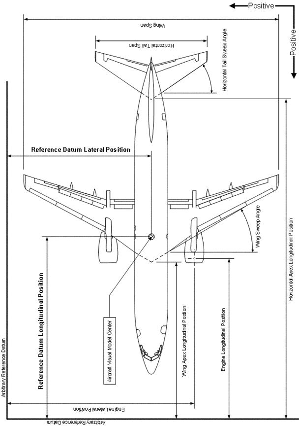
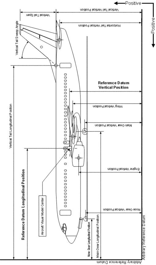
The Configuration tab contains the fields with which you can edit the geometry of the lifting surface and the empennage (tail feathers). You can also change the Reference Datum location of your aircraft. During the following discussion, refer to Figures 2, 3, and 4.
The visual model of every aircraft has a center. To ensure that the behavior of the aircraft in the simulation matches that of the visual model, you must define a reference datum relative to the visual model center point (see the table below). You can choose any reference datum. However, most aircraft reference documents define the position of certain parts of an aircraft relative to a reference datum, so choosing a similar location may make it easier to design your aircraft.
Once the reference datum is set, all dimensions you provide in FSEdit should be relative to this reference datum, not relative to the visual model center. For example, you might define the longitudinal reference datum 35 feet forward (positive) of the visual model center. If your wing position is 7 feet forward (positive) of the visual model center, then the longitudinal position of your wing would be -28 feet behind (negative) of the reference datum (28 + 7 = 35). For help regarding these definitions, refer to Figures 2 through 4.
Parameter |
Description |
|
|
Offset (in feet) of the aircraft's longitudinal reference datum from the visual model center point. Typically, for aircraft shipped with Flight Simulator, this point is on the aircraft centerline, chord aft of the leading edge. By setting the Reference Datum Position, actual aircraft loading data can be used directly according to the aircraft's manufacturer. If not specified, the default is 0 (Flight Simulator's visual model default center). |
|
|
Offset (in feet) of the aircraft's lateral reference datum from the visual model center point. Typically, for aircraft shipped with Flight Simulator, this point is on the aircraft centerline. By setting the Reference Datum Position, actual aircraft loading data can be used directly according to the aircraft's manufacturer. If not specified, the default is 0 (Flight Simulator's visual model default center). |
|
|
Offset (in feet) of the aircraft's vertical reference datum from the visual model center point. Typically, for aircraft shipped with Flight Simulator, this point is on the aircraft centerline. By setting the Reference Datum Position, actual aircraft loading data can be used directly according to the aircraft's manufacturer. If not specified, the default is 0 (Flight Simulator's visual model default center). |
In addition to the reference datum, the wing and tail geometry are needed.
Parameter |
Description |
|
|
The area of the top surface of the entire wing (tip-to-tip), in square feet. |
|
Wing Span |
The horizontal distance from wing-tip to wing-tip, in feet. Refer to Figure 2. |
|
Root Chord |
The length of the wing chord (leading edge to trailing edge) at the intersection of the wing and the fuselage, in feet. |
|
Dihedral |
When looking at the front of an aircraft, the angle between the wing leading edge and a horizontal line parallel to the ground, in degrees. Refer to Figure 4. |
|
Incidence |
When looking at the side of an aircraft from the wing tip, the angle the mean wing chord makes with a horizontal line parallel to the ground, in degrees. |
|
Twist |
The difference in wing incidence from the root chord and the tip chord of the wing, in degrees. Also known as wash-out. |
|
Oswald Efficiency Factor |
A measure of the aerodynamic efficiency of the wing. Also known as the Span Efficiency Factor. A theoretically perfect wing has an OEF of 1.0. |
|
Winglets? |
Boolean to indicate if the aircraft incorporates the use of winglets; 0 = FALSE, 1 = TRUE. |
|
LE Sweep |
When looking down on top of an aircraft, the angle the wing leading edge makes with a horizontal line perpendicular to the fuselage, in degrees. Refer to Figure 2. |
|
Wing Apex Longitudinal Position |
The longitudinal distance of the wing apex (measured at centerline of aircraft) from defined reference point, in feet. This distance is measured positive in the forward (out the aircraft nose) direction. Refer to Figure 2. |
|
Wing Apex Vertical Position |
The vertical distance of the wing apex (measured at centerline of aircraft) from defined reference point, in feet. This distance is measured positive in the up direction. Refer to Figure 3. |
|
Horizontal Tail Area |
The area of the top surface of the entire horizontal tail (tip-to-tip), in square feet. |
|
Horizontal Tail Span |
The horizontal distance from horizontal tail-tip to horizontal tail -tip, in feet. Refer to Figure 2. |
|
HTail/Canard Apex Longitudinal Position |
The longitudinal distance of the horizontal tail (or canard) apex (measured at centerline of aircraft) from defined reference point, in feet. This distance is measured positive in the forward (out the aircraft nose) direction. Refer to Figure 2. |
|
HTail/Canard Apex Vertical Position |
The vertical distance of the horizontal tail (or canard) apex (measured at centerline of aircraft) from defined reference point, in feet. This distance is measured positive in the up direction. Refer to Figure 3. |
|
Horizontal Tail Incidence |
When looking at the side of an aircraft from the horizontal tail tip, the angle the mean horizontal tail chord makes with a horizontal line parallel to the ground, in degrees. |
|
Horizontal Tail Sweep |
When looking down on top of an aircraft, the angle the horizontal tail leading edge makes with a horizontal line perpendicular to the fuselage, in degrees. Refer to Figure 2. |
|
Vertical Tail Area |
The area of the surface of one side of the vertical tail (fuselage-to-tip), in square feet. |
|
Vertical Tail Span |
The vertical distance from the vertical tail-fuselage intersection to the tip of the vertical tail, in feet. Refer to Figure 3. |
|
Vertical Tail Sweep |
When looking at the side of the vertical tail, the angle the vertical tail leading edge makes with a vertical line perpendicular to the fuselage, in degrees. Refer to Figure 3. |
|
VTail Apex Longitudinal Position |
The longitudinal distance of the vertical tail apex (measured at centerline of aircraft) from defined reference point, in feet. This distance is measured positive in the forward (out the aircraft nose) direction. Refer to Figure 3. |
|
VTail Apex Vertical Position |
The vertical distance of the vertical tail apex (measured at centerline of aircraft) from defined reference point, in feet. This distance is measured positive in the up direction. Refer to Figure 3. |
The Controls tab provides the fields in which you can change the geometry of the aircraft controls and deflections.
|
Parameter |
Description |
|
Elevator Area |
The area of the top surface of the entire elevator (tip-to-tip), in square feet. The elevator is the control surface on the horizontal tail. |
|
Aileron Area |
The area of the top surface of all the ailerons on the wing, in square feet. The ailerons are the control surfaces on the most outboard, trailing edge section of a wing. |
|
Rudder Area |
The area of the side surface of the entire rudder, in square feet. The rudder is the control surface on the vertical tail. |
|
Elevator Up Deflection Limit |
The angular limit of the elevator when deflected up, in degrees. |
|
Elevator Down Deflection Limit |
The angular limit of the elevator when deflected down, in degrees. |
|
Aileron Up Deflection Limit |
The angular limit of the aileron when deflected up, in degrees. |
|
Aileron Down Deflection Limit |
The angular limit of the aileron when deflected down, in degrees. |
|
Rudder Deflection Limit |
The angular limit of the rudder deflection, in degrees. Symmetrical deflection. |
|
Elevator Trim Deflection Limit |
The angular limit of the elevator trim tab, in degrees. |
|
Spoiler Deflection Limit |
The angular limit of the wing spoilers on an aircraft, in degrees. If this limit is zero, no spoilers exist for the aircraft. |
|
Spoilerons Available? |
Boolean to indicate if the spoilers also behave as spoilerons for roll control (if spoilers are available); 0 = FALSE, 1 = TRUE. |
The Flaps tab allows you to add, delete and modify a flap set. An aircraft can have a maximum of five flaps sets (indices from 0 to 4), and a minimum of no flaps. The Flap Set Selector window displays the currently available flap sets, and by selecting a flap set, the information in the Flap Set Editor changes to reflect the properties for that particular flap set. If no flap sets are available, the information in the Flap Set Editor is set to NULL defaults.
Click the Add Flap Set button on the top left of the Flaps tab.
Select the flap set you want to delete from the Flap Set Selector.
Click the Delete Flap Set button on the top right of the Flaps tab.
You cannot delete the last flap set in the window. However, if you want to have an airplane with no flaps, make sure that the Flap Type in the Flap Set Editor for the only flap set is set to None.
Parameter |
Description |
|
Type |
Indicates if this is a leading edge flap set, trailing edge flap set, or no flap set. |
|
Span |
The percentage of half-wing span to which the flap extends (from the wing-fuselage intersection). This value must be between 0 and 1 (0 and 100 percent). |
|
Extending Time |
The time it takes for the flap set to extend to the fullest deflection angle specified, in seconds. |
|
Damaging Speed |
The speed at which the flaps begin to accrue damage, in Knots Indicated Airspeed (KIAS). |
|
Blowout Speed |
The speed at which the flaps depart the aircraft, in Knots Indicated Airspeed (KIAS).. |
|
Lift Scalar |
The percentage of total lift due to flap deflection that this flap set is responsible for at full deflection. |
|
Drag Scalar |
The percentage of total drag due to flap deflection that this flap set is responsible for at full deflection. |
|
Pitch Scalar |
The percentage of total pitch change due to flap deflection that this flap set is responsible for at full deflection. |
|
Flap System Type |
Indicates what type of system drives the flaps to deflect: Electric, Hydraulic, Pneumatic, Manual, or None. |
|
Flap Handle Index to Deflection Mapping |
Each element of the flaps-position array indicates the deflection angle to which the flaps will deflect, in degrees, at the respective flap handle index position. The largest deflection angle input is used for full flap deflection. |
The components of the Flap Set Editor are related only to the flap set you have selected. You can modify each flap set individually to whatever values you like. The three fields at the bottom of the Flaps tab are considered static. These fields contain values that are set regardless of how many flap sets you have (or dont have).
Parameter |
Description |
|
Design Cruise Speed |
The typical cruise speed of the aircraft in a clean (flaps up) configuration, in Knots True Airspeed (KTAS). |
|
Flaps Up Stall Speed |
The stall speed of the aircraft in a clean (flaps up) configuration, in Knots True Airspeed (KTAS). |
|
Flaps Down Stall Speed |
The stall speed of the aircraft in a dirty (flaps full down) configuration, in Knots True Airspeed (KTAS). |
As most pilots know, the weight and balance of an aircraft is extremely important to its overall stability and performance. There are four main groupings on the Weight and Balance tab:
Gross Weight
Empty Weight
Payload Weight
Moments of Inertia
Note that the location of the weight components is very important to the aircrafts stability. Therefore, if undesirable handling qualities result for your aircraft, you may want to shift the weight components longitudinal location fore or aft until a stable configuration results.
The Gross Weight is the total weight the aircraft was designed to carry, including fuel and payload. This value is not used directly to simulate the aircraft in Flight Simulator 2002, but it is a very important component when determining the aerodynamic coefficients that make up the flight model. You must be sure that the Gross Weight value is greater than or equal to the empty weight + payload weight + fuel weight for your aircraft.
|
Parameter |
Description |
|
Gross Weight |
The maximum design gross weight of the aircraft, in pounds. |
The Empty Weight is the total structural weight of the aircraft, minus fuel and payload. You must also indicate a Center of Gravity (CG) location for the empty weight of the aircraft, relative to the previously defined Reference Datum. This location can be found through a summation of all the individual aircraft component weights and their locations, or you can use a best-guess estimate. Normally, the Empty Weight CG lies somewhere along the lateral and vertical centerline of a symmetrical aircraft, and between the leading edge and trailing edge of the wing-fuselage intersection.
|
Parameter |
Description |
|
Empty Weight |
The total weight (in pounds) of the aircraft minus usable fuel, passengers, cargo, and expendable armament (Combat Flight Simulator aircraft). |
|
Empty Weight Longitudinal Position |
The longitudinal offset (in feet) of the center of gravity of the basic empty aircraft (no fuel, passengers, or baggage) from the Reference Datum Position. |
|
Empty Weight Lateral Position |
The lateral offset (in feet) of the center of gravity of the basic empty aircraft (no fuel, passengers, or baggage) from the Reference Datum Position. |
|
Empty Weight Vertical Position |
The vertical offset (in feet) of the center of gravity of the basic empty aircraft (no fuel, passengers, or baggage) from the Reference Datum Position. |
You can use the Payload Weight Editor in the same way that you use the Flap Set Editor. Each station_load has a weight, as well as longitudinal, lateral and vertical position associated with it. You can add payload stations, delete payload stations, or modify the characteristics of a particular payload station. In addition, suggested values will be given that are dependent upon your empty weight and geometrical inputs. Although these values are a good guideline, some aircraft can have moments of inertia (MOIs) that vary significantly from these estimated values.
Parameter |
Description |
|
Empty Weight Pitch MOI |
The moment of inertia about the lateral axis. |
|
Empty Weight Roll MOI |
The moment of inertia about the longitudinal axis. |
|
Empty Weight Yaw MOI |
The moment of inertia about the vertical axis. |
|
Empty Weight Coupled MOI |
The moment of inertia about the roll and yaw axis (usually zero for symmetrical airplanes). |
The Engine tabs available depend on the type of engine used for your aircraft. For example, a jet aircraft does not have Piston Engine or Propeller tabs, and a glider does not have any engine or Fuel tab.
The Piston Engine tab is available for any aircraft that incorporates a piston engine. Normally, these aircraft also require a propeller to produce thrust. The propeller properties are on a separate tab, discussed later in this document.
The Piston Engine tab includes three main sections:
Piston Engine Properties
Turbocharger Properties
Engine Position
The Piston Engine Properties and Engine Position sections are required fields; the Turbocharger is optional.
A piston engines power can be determined through a series of equations that represent the Otto cycle of a four-stroke piston engine, multiplied by the number of pistons available. This section contains all the information that Flight Simulator needs to determine how much power the engine can produce.
Parameter |
Description |
|
Cylinder Displacement |
The displacement in cubic inches of each cylinder. |
|
Compression Ratio |
The compression ratio of each cylinder. |
|
Number of Cylinders |
The number of cylinders in the engine. |
|
Max Rated RPM |
The maximum rated revolutions per minute (RPM) of the engine (red line). |
|
Max Rated Horsepower |
The maximum rated brake horsepower output of the engine. |
|
Fuel Flow Scalar |
The scalar for modifying the fuel flow required by the engine(s). A value of less than 1.0 causes a slower fuel consumption for a given power setting, a value greater than 1.0 causes the aircraft to burn more fuel for a given power setting. |
|
Cooling Type |
A drop-down box indicating the method of engine cooling: Air Cooled or Liquid Cooled. |
|
Carburetor Type |
A drop-down box indicating the type of carburetor used: Fuel Injected, Gravity, or Aerobatic Carburetor. |
If you want a turbocharged engine, select the Turbocharged? check box at the top-right corner of the Turbocharger Properties section. After you select this check box, you can edit the other fields for that section.
|
Parameter |
Description |
|
Turbocharged? |
A check box that indicates if the engine is turbocharged. |
|
Max Design Manifold Pressure |
The maximum design manifold pressure supplied by the turbocharger, in inches of mercury (inHg). |
|
Min Design Manifold Pressure |
The minimum design manifold pressure of the turbocharger, in inches of mercury (inHg). |
|
Critical Altitude |
The altitude, in feet, at which the turbocharger will provide the maximum design manifold pressure. |
|
Emergency Boost Type |
A drop-down box indicating the emergency boost type available: None, Water Injection, Methanol/Water Injection, or War Emergency Power (typically used in WWII combat aircraft). |
|
Emergency Boost Manifold Pressure |
The additional manifold pressure supplied by emergency boost, if available, in inches of mercury (inHg). |
|
Emergency Boost Gain |
The multiplier on manifold pressure due to emergency boost. A suggested value is provided for a given emergency boost Manifold Pressure and Critical Altitude. |
In addition to the parameters needed to compute the power available from a piston engine, the engine position(s) must also be identified. After you select the number of engines from the Number of Engines drop-down box, you can edit the corresponding position fields.
Parameter |
Description |
|
Engine Longitudinal Position |
The longitudinal offset (in feet) of the engine from the Reference Datum Position (see Figure 2). |
|
Engine Lateral Position |
The lateral offset (in feet) of the engine from the Reference Datum Position (see Figure 2). |
|
Engine Vertical Position |
The vertical offset (in feet) of the engine from the Reference Datum Position (see Figure 3). |
A turboprop engine is similar to a jet engine (turbine), but it incorporates the use of a propeller turned by the shaft of the turbine engine to produce thrust. The parameters here determine the power output of the turboprop engine.
Parameter |
Description |
|
Maximum Torque |
The maximum shaft torque available from the engine, in foot-pounds. |
|
Static Thrust |
The residual thrust available from the turbine engine in addition to that provided by the propeller, in pounds. |
|
Inlet Area |
The turbine engine nacelle inlet area, in square feet. |
|
Rated RPM |
The maximum design RPM of the turbine compressor. |
|
Fuel Flow Scalar |
The scalar for modifying the fuel flow required by the engine(s). A value of less than 1.0 causes a slower fuel consumption for a given power setting, a value greater than 1.0 causes the aircraft to burn more fuel for a given power setting. |
In addition to the parameters needed to compute the power available from a turboprop engine, the engine position(s) must also be identified. After you select the number of engines from the Number of Engines drop-down box, you can edit the corresponding position fields.
Parameter |
Description |
|
Engine Longitudinal Position |
The longitudinal offset (in feet) of the engine from the Reference Datum Position (see Figure 2). |
|
Engine Lateral Position |
The lateral offset (in feet) of the engine from the Reference Datum Position (see Figure 2). |
|
Engine Vertical Position |
The vertical offset (in feet) of the engine from the Reference Datum Position (see Figure 3). |
The Jet Engine tab is available for an aircraft that is a pure jet (turbine engine with no propeller). This type of engine is also synonymous with a Turbofan or Turbojet engine. For example, the Learjet 45 and the Boeing 737-400 are both aircraft that incorporate the use of a Jet Engine.
|
Parameter |
Description |
|
Static Thrust |
The maximum rated static thrust at sea level, in pounds. |
|
Inlet Area |
The engine nacelle inlet area, in square feet. |
|
Rated N2 RPM |
The rated RPM of the second-stage compressor. |
|
Fuel Flow Scalar |
The scalar for modifying the fuel flow required by the engine(s). A value of less than 1.0 causes a slower fuel consumption for a given power setting, a value greater than 1.0 causes the aircraft to burn more fuel for a given power setting. |
|
Afterburner Available? |
A check box that indicates if an afterburner is available. |
|
Thrust Reverser Available? |
A check box that indicates if a thrust reverser is available. |
In addition to the parameters needed to compute the thrust available for a jet engine, the engine position(s) must also be identified. After you select the number of engines from the Number of Engines drop-down box, you can edit the corresponding position fields.
Parameter |
Description |
|
Engine Longitudinal Position |
The longitudinal offset (in feet) of the engine from the Reference Datum Position (see Figure 2). |
|
Engine Lateral Position |
The lateral offset (in feet) of the engine from the Reference Datum Position (see Figure 2). |
|
Engine Vertical Position |
The vertical offset (in feet) of the engine from the Reference Datum Position (see Figure 3). |
You can use the Propeller tab with piston or turboprop engines. The propeller is the main producer of thrust for these types of engines. This tab is available only for aircraft with a piston or turboprop engine.
The thrust generated by the propeller is a function of the power delivered through the propeller shaft (determined from the respective engine properties), RPM, blade angle, airplane speed, and ambient density. The following parameters are needed to compute the thrust for aircraft with propellers.
Parameter |
Description |
|
Propeller Type |
A drop-down box that identifies what type of propeller is on the aircraft: Constant Speed or Fixed Pitch. |
|
Propeller Diameter |
The diameter of propeller blades, tip to tip, in feet. |
|
Number of Blades |
The integer value indicating the number of blades on the propeller. |
|
Propeller MOI |
The propeller moment of inertia, in slug ft2. |
|
Max Pitch Angle |
The maximum blade pitch angle for constant speed prop (not available if fixed pitch), in degrees. |
|
Min Pitch Angle |
The minimum blade pitch angle for constant speed prop (not available if fixed pitch), in degrees. |
|
Fixed Pitch Angle |
The blade pitch angle for fixed pitch prop (not available if constant speed), in degrees. |
|
Min Governed RPM |
The minimum RPM controlled by the governor for a constant speed prop. |
|
Gear Reduction Ratio |
The reduction ratio from the engine output RPM to prop RPM. |
|
Prop Sync Available? |
A check box that indicates if propeller-sync is available (twin-engine aircraft). |
|
Prop Deice Available? |
A check box that indicates if propeller de-icing is available. |
|
Prop Feathering Available? |
A check box that indicates if prop feathering is available (constant-speed prop only). |
|
Prop Auto Feathering Available? |
A check box that indicates if prop auto-feathering is available (constant-speed prop only). |
|
Min RPM for Feathering |
The minimum RPM at which the prop will feather (if feathering is available). |
|
Feathered Pitch Angle |
The propeller pitch angle when feathered in degrees. |
|
Prop Reverse Available? |
A check box that indicates if prop reverse is available (constant-speed prop only). |
The Fuel tab is available for any aircraft with an engine; if you are developing a glider, the fuel tab is unavailable.
You can include up to 11 fuel tanks, but if the Total Capacity value for a tank is zero, that tank is not used. The following values apply to each of the 11 possible tank configurations.
|
Parameter |
Description |
|
Fuel Tank Longitudinal Position |
The longitudinal offset (in feet) of the fuel tank centroid from the Reference Datum Position (see Figure 2). |
|
Fuel Tank Lateral Position |
The lateral offset (in feet) of the fuel tank centroid from the Reference Datum Position (see Figure 2). |
|
Fuel Tank Vertical Position |
The vertical offset (in feet) of the fuel tank centroid from the Reference Datum Position (see Figure 3). |
|
Total Capacity |
The total capacity of the individual fuel tank, in gallons. |
|
Unusable Capacity |
Typically, there is some amount of fuel stored in the fuel lines that cannot get to the engine. This quantity is subtracted from the Total Capacity to get a Usable Fuel Capacity, in gallons, per tank. |
Every aircraft should have ground reaction contact points associated with it (otherwise, your airplane would never touch the ground). On this tab, you can add, delete, or modify individual contact points. The Point Selector identifies the active point in the Gear/Scrape Point Editor section.
You can configure and adjust the way aircraft react to different kinds of contact, including landing gear contact and articulation, braking, steering, and damage caused by excessive speed. You can also configure each contact point independently for each aircraft, and there is no limit to the number of points you can add.
You must specify the gear (or skid or float) points and any scrape points that identify aircraft contact with the ground. For example, you should place a scrape point at each wing tip so that if the tip scrapes the ground, the aircraft is damaged and the wing does not go through the ground. You should place scrape points at the following locations:
Nose
Wing tips (2)
Tail
Belly
Top of vertical tail
The following parameters apply to all types of contact points.
Element |
Description |
|
Point Class |
A drop-down box that defines the type of contact point; None, Wheel, Scrape, Skid, Float, Water Rudder. |
|
|
A drop-down box that defines which brake input drives the brake (wheels only): None, Left Brake, Right Brake. |
|
|
A drop-down box for mapping a type of sound to a specific point: Center Gear, Auxiliary Gear, Left Gear, Right Gear, Fuselage Scrape, Left Wing Scrape, Right Wing Scrape, Aux1 Scrape, Aux2 Scrape, Tail Scrape. |
|
|
The longitudinal distance of the point from the defined reference datum, in feet. Positive is forward (out the nose). Refer to Figure 3. |
|
|
The lateral distance of the point from the defined reference datum, in feet. Positive is starboard (right, as viewed from the top with the airplane pointing up). Refer to Figure 4. |
|
|
The vertical distance of the point from the defined reference datum, in feet. Positive is up. Refer to Figure 3. |
|
|
The speed at which an impact with the ground can cause damage, in feet per minute. |
|
|
The radius of the wheel, in feet. |
|
|
The maximum angle (positive and negative) that a wheel can pivot, in degrees. (Fully castoring tail-wheels should use 180 degrees). |
|
|
The distance a landing gear is compressed when the empty aircraft is at rest on the ground, in feet. This term defines the strength of the strut, where a smaller number increases the stiffness of the strut. |
|
|
The ratio of the maximum dynamic compression available in the strut to the static value. Can be useful in coordinating the compression of the strut when landing. |
|
|
This ratio describes how well the ground reaction oscillations are damped. A value of 1.0 is considered critically damped, meaning there is little or no oscillation. A damping ratio of 0.0 is considered undamped, meaning that the oscillations continue with a constant magnitude. Negative values result in unstable ground handling, and values greater than 1.0 might also cause instabilities by being over-damped. Typical values range from 0.6 to 0.95. |
|
|
The amount of time it takes the landing gear to extend fully under normal conditions, in seconds. A value of zero indicates a fixed gear. |
|
|
The amount of time it takes the landing gear to retract fully under normal conditions, in seconds. A value of zero indicates a fixed gear. |
In addition to the above point-specific parameters, two static parameters apply to the aircraft, regardless of the number or type of contact points.
Parameter |
Description |
|
Static Pitch Angle |
The static pitch of the aircraft when it is at rest on the ground, in degrees. The program uses this value to position the aircraft at startup, in slew mode, and at any other time when the simulation is not running. |
|
Static CG Height Above Ground |
The static height of the aircraft when it is at rest on the ground, in feet. The program uses this value to position the aircraft at startup, in slew mode, and at any other time when the simulation is not actively running. |
The Tuning tab is a very important part of process of aircraft flight models. Although the theory used to calculate the aerodynamic coefficients is reliable and well-proven, you must make many assumptions made in order to simplify the aircraft design process. You will invariably need to change the values of some parameters to make an aircraft behave in the air as you expect it to.
You can tune five main areas:
Flight Control Effectiveness
Stability Characteristics
Lift Forces
Drag Forces
Engine Parameters
The tuning of these parameters can be considered mostly independent of each other, although some coupling (the effect of one parameter on another) can occur.
The following parameters are multipliers on the aerodynamic power of the control surfaces. For example, an Elevator Effectiveness value of 1.1 increases the elevator effectiveness by 10 percent. Likewise, a value of 0.9 decreases the effectiveness by 10 percent. A negative number reverses the normal effect of the control.
Parameters |
What it scales |
|
Elevator Effectiveness |
The change that results when moving the elevator, which affects the aircrafts rotation about the lateral axis. |
|
Aileron Effectiveness |
The change that results when moving the aileron, which affects the aircrafts rotation about the longitudinal axis. |
|
Rudder Effectiveness |
The change that results when moving the rudder, which affects the aircrafts rotation about the vertical axis. |
The following parameters are multipliers on the aerodynamic stability (damping effect) of the aircraft, about the corresponding axis of the airplane. For example, a Pitch Stability value of 1.1 increases the pitch damping by 10 percent. Likewise, a value of 0.9 decreases the pitch damping by 10 percent. A negative number results in an unstable characteristic about that axis. A positive damping effect is simply a moment in the direction opposite of the rotational velocity, or a restoring moment.
Parameters |
What it scales |
|
Pitch Stability |
The stability of the aircraft about the lateral axis. |
|
Roll Stability |
The stability of the aircraft about the longitudinal axis. |
|
Yaw Stability |
The stability of the aircraft about the vertical axis. |
The Cruise Lift Scalar is a multiplier on the coefficient of lift at zero angle of attack ('cruise lift' in this context refers to the lift at relatively small angles of attack, which is typical for an airplane in a cruise condition). The effect of this parameter is decreased linearly as the angle of attack moves toward the critical (stall) angle of attack, preventing destabilization at low speed and high angles of attack.
Modify this value to tune the angle of attack (and thus pitch angle) for your aircraft while in the cruise condition. A negative value results in extremely unnatural flight characteristics.
Parameter |
What it scales |
|
Cruise Lift Scalar |
Lift Coefficient at Zero Angle of Attack, (CL0). |
Drag is the aerodynamic force that opposes thrust, which in turn helps determine the aircrafts speed and acceleration. You can adjust two basic types of drag:
Parasite Drag (due to friction)
Induced Drag (due to lift)
Parasitic drag is composed of two basic elements: form drag, which results from the interference of streamlined airflow, and skin friction. Parasitic drag increases as speed increases.
Induced drag results from the production of lift, which increases as angle of attack increases (until the stall angle is reached). The total drag force on an aircraft is the sum of these two components.
The following parameters are multipliers on the two respective drag coefficients. For example, a Parasite Drag value of 1.1 increases the respective drag component by 10 percent. A value of 0.9 decreases the parasite drag by 10 percent. Negative values result in extremely unnatural flight characteristics.
Parameter |
What it scales |
|
Parasite Drag |
Zero Lift Drag Coefficient, (CD0). |
|
Induced Drag |
Induced Drag Coefficient, (CDi). |
The tuning scalars (which affect engine performance) that are available depend on the type of engine your aircraft uses. Thrust is associated with a turbine engine or propeller, while power is associated with a piston or turboprop.
The mechanical efficiency and friction scalars are associated only with a piston engine, and they provide a means by which the maximum RPM and the idle RPM can be tuned.
Parameter |
What it scales |
|
Thrust scalar |
The calculated thrust provided by the propeller or jet. |
|
Power scalar |
The amount of power delivered by the engine to the propeller shaft. |
|
Max RPM Mechanical Efficiency Scalar |
The mechanical efficiency of the engine at maximum RPM. Increase this value to increase the mechanical efficiency, decrease it to decrease the mechanical efficiency. |
|
Idle RPM Mechanical Efficiency Scalar |
The mechanical efficiency of the engine at idle RPM. Increase this value to increase the mechanical efficiency, decrease it to decrease the mechanical efficiency. |
|
Max RPM Friction Scalar |
The internal friction of the engine at maximum RPM. Increase this value to increase the friction, decrease it to decrease the friction. |
|
Idle RPM Friction Scalar |
The internal friction of the engine at idle RPM. Increase this value to increase the friction, decrease it to decrease the friction, (can be used to tune the RPM at which the engine idles). |
|
Politica de confidentialitate | Termeni si conditii de utilizare |

Vizualizari: 4921
Importanta: ![]()
Termeni si conditii de utilizare | Contact
© SCRIGROUP 2025 . All rights reserved