| CATEGORII DOCUMENTE |
| Bulgara | Ceha slovaca | Croata | Engleza | Estona | Finlandeza | Franceza |
| Germana | Italiana | Letona | Lituaniana | Maghiara | Olandeza | Poloneza |
| Sarba | Slovena | Spaniola | Suedeza | Turca | Ucraineana |
DOCUMENTE SIMILARE |
|||||
|
|||||
TERMENI importanti pentru acest document |
|||||
Lesson Title: Aliasing Applications (#1)
|
|
![]()
Background:
The study, to date, has focused on one-dimensional signals. Sampling and alias analysis procedures have been developed and exemplified. Multi-dimensional, and two-dimensional signals are equally important. Regardless of the domain, it is important to realize that sampling and alias maintenance procedures are widely interpreted and applied by the modern DSP engineer.
Challenge:
Images
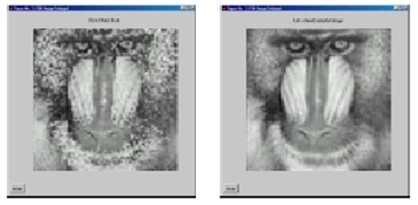
Images can suffer from several types of sample related abnormalities. Sampling artifacts are shown in Figure 1. They occur when the sampling (imaging) system is too coarse to detect the image's finest details. This is familiar effect and can be mitigated, to some degree, using interpolation techniques.
|
Figure 1: Images with various degrees of artifact corruption. |
Images, as signals, can be corrupted by aliasing effects.
Image aliasing occurs when image motion is too fast relative to the sample of
frame rate. The result, upon reconstructing the image, is something that
impersonates (alias) another image. As a youth you may recall seeing your first
Undersampling
Software defined radios (SDR) will use DSP technology to increase system
robustness and functionality. Today one can find radios that operate at
comparatively low frequencies (30-400 MHz) and narrow bandwidths
(12.5-25 kHz), newer systems operate at higher frequencies
(960-2400 MHz) with higher bandwidths (25-100+ MHz), and
higher frequency systems due to be released in the near future. A key strategy
involved in defining these new systems will be closing the gap between the
radios digital processor and antenna. Today, direct RF to baseband conversion
is only possible in those instances where the RF signals can be sampled at or
above the Nyquist frequency. For mobile low power solutions, this is currently
limited to 100-300 MHz. In most cases, multiple intermediate frequency
(IF) stages are required to translate the signal down to a frequency range
where it can be Nyquist sampled (see Figure 2).
|
Figure 2: A superheterodyne receiver (a) using a Nyquist sampler. Undersampled receiver (b) sampled below the Nyquist criterion. (BPF=bandpass filter, LO=local oscillator) |
RF SAW ADC
![]()
![]()
![]()
![]()
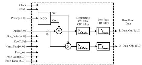
Figure 3. Digital IF
Receiver Megafunction Block Diagram
Another type of receiver architecture, called an undersampled ADC (a.k.a., bandpass conversion, direct RF conversion, IF sampling, harmonic sampling, or super-Nyquist sampling), is an option in those cases where Nyquist sampling is impractical. The undersampled ADC solution depicted in Figure 2(b), shows the undersampler to act as a mixer, translating the B Hz information band down to baseband. This technique often eliminates the need for additional IF stages, where the elimination of a single IF stage can reduce the cost of a receiver by $10 to $100. Buchanan [Buc02] also noted that to successfully design an undersampled system, rigorous frequency planning is required to ensure that the signals of interest are not located at or near the boundaries defined by multiples of the Nyquist frequency. ADCs are typically run at a rate at least 2.5 times the information bandwidth B. It is important to note that the minimum sampling rate is set by the bandwidth of the information process. This assumes that unwanted signal energy from other bands being aliased to baseband is heavily attenuated. Designers of undersampled systems rely on an abilty to alias desired information band into the middle of the baseband and reject all other potential alias sources. Consider again the example shown in Figure 2 and note that a 12 MHz information process found at IF1=180 MHz, will be aliased down to 20 MHz upon sampling (i.e., 20=180mod(80)), which is in the middle of the baseband defined by the ADC clock (fs=80 MHz). The aliased information band extends from 20 MHz-12 MHz=8 MHz out to 20 MHz+12 MHz=32 MHz < 40 MHz = fs/2.
Nava engineering markets a digital IF receiver megafunction (i.e., FPGA design) that combines a quadrature NCO and a digital mixer to translate the input IF signal down to baseband. A pair of cascaded integrator comb (CIC) filters, and FIR filters provide decimation and bandlimiting to accommodate a range of signal bandwidths as suggested in Figure 3. Megafunction uses a quadrature NCO, two digital mixers, two 4th order decimating CIC filters, and two FIRs.
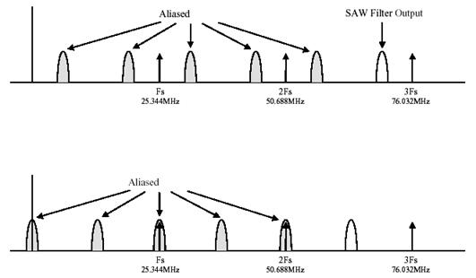
Figure 4 illustrates the frequency
down conversion process using IF undersampling. In this example, the ADC is
operated at a 25.344MHz sampling rate. This rate is below the desired signal of
interest, so we must be very careful to choose an ADC with an IF undersampling
capability, suitable for this application example. The ADC samples the
bandlimited signal presented at the output of the bandpass surface acoustic
wave (SAW) filter. The signal of interest is centered at an IF of 70MHz. The
ADC sampling action will produce aliased images of the SAW output, centered
around the sampling frequencies nfs,
where n = 0, 1, 2, . Notice the
lowest positive frequency image is centered at 6.032MHz. The second panel in
Figure 4 shows the result of the signal spectrum after down conversion (i.e. frequency translation). In this
specific example, the NCO is tuned to 6.032MHz. When the ADC samples are mixed,
or multiplied with the NCO output, the entire spectrum is shifted, or slid,
down in frequency by 6.032MHz. The IF undersampling and downconversion process
have translated the signal of interest (a purely real signal located at 70MHz)
down to baseband (a complex signal located at 0Hz). The downcoverters and mixer
are commercially available. The question posed is how do you specify the ADC
requirements?
Figure 4: Example of frequency down conversion
Responses
Image Aliasing
The stagecoach wheel first appeared moving at a leisurely pace of one revolution per second (12 per fame at 30 frames per soncond) in a counterclockwise direction. Then all ell breaks loose and the stagecoach's wheel is now turning at a rate around 30 revolutions per second. If the wheel rotational rate is 348 degrees per frame, then it would appear to the viewer to be turning at a 12 per fame rate (348 =360 -12 per fame) or one revolution per second but in a clockwise direction (aliased). . If the wheel rotational rate is 372 degrees per frame, then it would appear to the viewer to be turning at a 12 per fame rate (372 =360 +12 per fame), or a slow one revolution per second but in a counterclockwise direction (aliased).
2. Undersampling
The problem is one of analog sample and hold delays. While digitizing signals at a 80 MHz rate is unchallenging in light of today's technology, finding devices that can work at the sample and hold rates required of the first IF stage rates are not. The first IF at 180 MHz 12 MHz, would require a minimum Shannon-defined sample rate on the order of 400 M Sa/s or a sample period of 5 ns. Using a 80 MHz sampler would provide to wide a sampling aperture, excessively smoothing the IF signal's details, rendering the IF signal useless.
There are ADC that are designed for this application. A few are reviewed below.
Analog Devices AD943312-Bit 105/125 MSPS Analog-To-Digital IF Sampling Converter (www.analog.com)
Features
IF Sampling up to 350 MHz
SNR = 67.5 dB, Fin up to Nyquist at 105 MSPS
SFDR = 83 dBc, 70 MHz Fin at 105 MSPS
SFDR = 72 dBc, 150 MHz Fin at 105 MSPS
2
On-Chip Clock Duty Cycle Stabilization
On-Chip Reference and Track/Hold
SFDR Optimization Circuit
Excellent Linearity - DNL = 0.25 LSB (Typ) - INL = 0.5 LSB (Typ)
750 MHz Full Power Analog Bandwidth
Power Dissipation = 1.35W at 125 MSPS
Two's Complement or Offset Binary Data Format
Applications
Cellular Infrastructure Communication Systems
Wideband Carrier Frequency Systems
Communications Test Equipment
Radar and Satellite Ground Systems
Analog Devices AD11405 14-Bit, 105 MSPS Analog to Digital Converter Optimized for IF Sampling(www.analog.com)
Features
105 MSPS sample rate
IF Sampling to 200 MHz
85dB
Twos Complement Output Format
3.3V Compatible Outputs
2.5 Watt
Analog Input BW 300 MHz
Applications
Phased Array Receivers
Multi-Channel, Multi-Mode Receivers
GPS Anti-Jamming Receivers
Communications Receivers
Instrumentation
Basestation
Maxim ADC (www.maxim-ic.com)
The MAX1005 is a combined digitizer and reconstruction integrated circuit designed to work in systems that demodulate and modulate communications signals. It integrates IF undersampling and signal synthesis functions into a single, low-power circuit. Its analog-to-digital converter (ADC) is used to directly sample or undersample a downconverted RF signal, while its digital-to-analog converter (DAC) recreates the IF subcarrier and transmission data. The MAX1005s ADC is ideal for undersampling applications, due to the analog input amplifiers wide (15MHz) bandwidth. The DAC has very low glitch energy, which minimizes the transmission of unwanted spurious signals. An on-chip reference provides for low-noise ADC and DAC conversions.
Sources:
Nova Engineering (www.navaengineering.com) Digital IF
Receiver Nova Engineering Megafunction, Data Sheet PN F901SC, Dec. 2001
|
Politica de confidentialitate | Termeni si conditii de utilizare |

Vizualizari: 2375
Importanta: ![]()
Termeni si conditii de utilizare | Contact
© SCRIGROUP 2026 . All rights reserved