| CATEGORII DOCUMENTE |
| Bulgara | Ceha slovaca | Croata | Engleza | Estona | Finlandeza | Franceza |
| Germana | Italiana | Letona | Lituaniana | Maghiara | Olandeza | Poloneza |
| Sarba | Slovena | Spaniola | Suedeza | Turca | Ucraineana |
This textbook is an introductory
course to the general topic of Mechanics of Materials and is intended to
gradually expose the students, enrolled in the Civil Engineering Section of the
Technical University of Bucharest, to this fundamental subject during the first
semester of their sophomore year instruction. The subject is known in the
Romanian technical literature as Strength
of Materials, but the more general title of Mechanics of Materials is widely employed for undergraduate studies
at the engineering colleges in the
The theory contained in this textbook represents the base knowledge for the professional life of any structural engineer. Without a doubt, the theoretical subjects covered in this textbook represent the foundation for thorough understanding of more advanced subjects that will confront the student during the undergraduate and graduate study years.
The Classical Mechanics, discipline studied in the previous year, had introduced the fundamental principals of Statics and Dynamics and applied them in the investigation of the particle and rigid body behavior, cases representing a drastic idealization of the real physical systems. The Mechanics of Materials concentrates on the study of the deformable solid body. The principal objective of this textbook is to familiarize the student with the basic concepts of deformation, stress and strain induced in a special category of deformable bodies, namely the beam, by external environmental actions. The validation of the theoretical derivations is achieved by confronting them with experimental results obtained during laboratory tests. The understanding of the mechanical behavior of the beams subjected to exterior actions is the most essential factor required for successful design of all types of structures such as: bridges, high-rise buildings, industrial buildings, power plants, aircrafts, spacecrafts, etc.
Note: Before elaborating about the scope and the main directions of the course, several conventions used in the text are described. Throughout the entire body of this textbook, the first instance usage of important terminology necessary to establish a base technical vocabulary is shown in boldface. Additionally, a selection of the most important definitions are enclosed in a box and presented using the italic font.
What is a Deformable Body?
The entire domain of Mechanics of Materials is concerned with developing the mathematical methodology necessary to completely define the behavior of the deformable solid body.
The mathematical description of the physical changes that take place, the modification of volume and shape, when the three-dimensional body is subjected to exterior actions, requires that two Cartesian orthogonal coordinate systems be employed: (1) a global coordinate system OXYZ, being considered as fixed in three-dimensional space, and (2) a local coordinate system oxyz, rigidly attached to the three-dimensional body. Consequently, a material point pertinent to the three-dimensional body can then be defined by two position vectors, each one relative the two coordinate systems. A schematic representation of the three-dimensional deformable body subjected to various actions and the Cartesian orthogonal coordinate systems described above are shown in Figure 1.1. The exterior actions are shown as concentrated vectors acting in some particular points (points 1 and 2), but in general the exterior actions have a more complex nature. The symbols attached to some material points (points 4, 5 and 6) of the three-dimensional body are the schematic representation of the supports or, more appropriately, constraints.
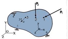
Figure1.1 Schematic Illustration of a Three-Dimensional Solid Deformable Body
Changes in the volume or shape
are generically referred to as deformations.
Consequently, any point of the three-dimensional body moves after the
application of the exterior action from its initial position to a new position
in space. For example the material point located in the position marked with
the numeral ![]() deforms into the new
position
deforms into the new
position![]() . The deformation of the solid body can be small or large,
but it plays a vital role in the analysis of the behavior the three-dimensional
solid under the given exterior actions.
. The deformation of the solid body can be small or large,
but it plays a vital role in the analysis of the behavior the three-dimensional
solid under the given exterior actions.
Geometrical Classification of the Deformable Body
In terms of geometry, any solid
body located in three-dimensional space is represented by its volume and
exterior surface. For this study the exterior surface is considered continuous
without any holes or interruptions. The volume is characterized by three
dimensions (length![]() width
width ![]() and height
and height ![]() ) or by one dimension and two ratios. For example, if the
length
) or by one dimension and two ratios. For example, if the
length![]() , typically the dimension of greatest magnitude, is retained,
than the ratios width to length
, typically the dimension of greatest magnitude, is retained,
than the ratios width to length ![]() and height to length
and height to length ![]() fully define the body.
The following categories of bodies can be defined as:
fully define the body.
The following categories of bodies can be defined as:
(a)
Member
or Beam is a three-dimensional solid
body which has the length ![]() much larger than the
other two dimensions. To be more prcised the major dimension
much larger than the
other two dimensions. To be more prcised the major dimension ![]() can be described by a curve called the member longitudinal axis. By intersecting the
three-dimensional volume with a normal plane to the longitudinal axis a surface
is obtained. This surface is the beam cross-section.
Usually the beam is defined:
can be described by a curve called the member longitudinal axis. By intersecting the
three-dimensional volume with a normal plane to the longitudinal axis a surface
is obtained. This surface is the beam cross-section.
Usually the beam is defined:
![]() (1.1)
(1.1)
The cross-section represented by a single surface is called compact, while the surface which has a central hole is called tubular. A special type of tubular cross-section is the thin-walls cross-section characterized by very thin wall thicknesses.
The analytical description of the beam longitudinal axis as a curve in space or plane curve can further differentiate this category into spatial and plane curved members. The plane members are linear (beam) or curved (arch) members.
Due to the simplicity of manufacturing, the linear member, known in the engineering practice under the generic name of the beam, is the most commonly employed structural element. The behavior of the linear beam is the main subject of this course. Examples of members are shown in Figure 1.2.
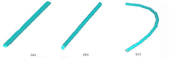
Figure 1.2 Examples of Member Types
(a) Rectangular-Linear, (b) Circular-Linear and (c) Circular-Curved
(b) Plate or Slab is a
three-dimensional solid body which has two of its three dimensions much larger
than the third one. The smallest dimension, usually called the thickness![]() , is replacing the height in the original definition. The
geometry of the plate median plane
or neutral plane, the plane
separating the thickness of the plate into two equal parts, can be represented
as a plane or a curved surface. The plate having a curved median plane is
called shell. By definition a plate
(slab) has the following ratios:
, is replacing the height in the original definition. The
geometry of the plate median plane
or neutral plane, the plane
separating the thickness of the plate into two equal parts, can be represented
as a plane or a curved surface. The plate having a curved median plane is
called shell. By definition a plate
(slab) has the following ratios:
![]() and
and ![]() (1.2)
(1.2)
where the dimensions ![]() and
and![]() are the length and width of the median plane, respectively.
are the length and width of the median plane, respectively.
If the thickness ![]() is very small
comparison with the other two dimensions, the plate is called membrane.
is very small
comparison with the other two dimensions, the plate is called membrane.
The plate is also a widely used structural component, but its behavior is the subject of another course. Examples of plates are depicted in Figure 1.3
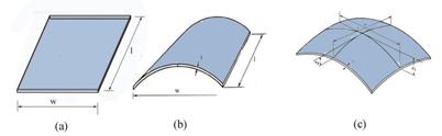
Figure 1.3 Plate Types
(a) Slab (Plane), (b) Cylindrical Shell and (c) Parabolic Shell
(c) Block is a three-dimensional solid body which has all of its three dimensions comparable.
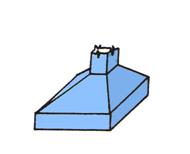
Figure 1.4 Isolated Foundation
In structural engineering this type of solids are encountered with predilection in all kind of buildings and machine foundations. An isolated foundation supporting a structural column is illustrated in Figure 1.4.
Note: It is important to emphasize that the geometrical characterization of the solid deformable body is also reflected in the mathematical model used in the description of each body type.
Exterior Action Classification
The exterior action contributing to the deformation of the three-dimensional solid can of mechanical or a thermal nature. In the engineering practice, these actions are labeled under the generic name of loads. The mechanical load is the direct result of the interaction of the three-dimensional deformable solid under investigation with other solids, liquids or gases. For example the wind action is mechanical load induced by the hydrodynamic pressure of the air movement. Similarly, the liquid contained in the reservoir impinges on the walls and a hydrostatic pressure results.
In general a mechanical load is
considered as continuous function of two variables![]() , where
, where ![]() the position vector of the material is point where the
function is described and
the position vector of the material is point where the
function is described and ![]() is the time.
is the time.
For the case of linear beam type
solid, the case of interest for this course, the spatial variable is described
only by the one-dimensional position vector and the function can be written as![]() . The mechanical load is a vectorial function, which is characterized by direction and intensity.
. The mechanical load is a vectorial function, which is characterized by direction and intensity.
The classification of the mechanical loads is conducted base on two criteria, both related with the intensity: (a) the time dependency and (b) the spatial variation.
Definition 1.2 If the intensity of the applied load changes with time the load is
called a dynamically applied load
or a dynamic load. As a result
the inertial forces, conforming to If the intensity of the applied load does not change in time the
load is called a statically applied
loads or a static load. In
this case there are no inertial forces to be included in the equations of
equilibrium.
The classification of the mechanical and thermal action as dynamic or static has only theoretical merit, because, any action is to some extent of dynamic nature. In fact, in some new textbooks the static loads are called quasi-dynamic loads in order to incorporate them in the same theory as the dynamic loads.
The spatial variability of the
function ![]() can be theoretically defined by any continuous mathematical
function. In engineering practice, these functions are typically limited for
simplicity to the following: constant function, linearly varying function and
parabolically varying function. For the rare case of more complicated spatial
variability the concept of piecewiseconstant
(stepped) or piecewise-linear
functions may be employed.
can be theoretically defined by any continuous mathematical
function. In engineering practice, these functions are typically limited for
simplicity to the following: constant function, linearly varying function and
parabolically varying function. For the rare case of more complicated spatial
variability the concept of piecewiseconstant
(stepped) or piecewise-linear
functions may be employed.
Examples of mechanical loads commonly used in the analysis of the linear plane beams are shown in Figure 1.5.
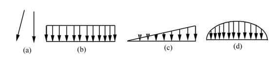
Figure 1.5 Line Mechanical Loads
(a) Concentrated, (b) Uniformly Distributed, (c) Linearly Distributed, and (d) Parabolically Distributed
In the reality all mechanical loads are applied on the surface of the solid body, which can be small or large. The application surface degenerates into a line segment in the theoretical case of the linear solid (beam). The situation when the area of the load application surface or the length of load application segment is small relative to the overall area or length of the three-dimensional body suggests the theoretical definition of the concentrated load.
Obviously the concentrated load can be static or dynamic in nature. This engineering simplification can be easily accommodated when dealing with the beam case, but creates some theoretical difficulties when the other two categories of deformable bodies (plates and blocks) are investigated.
A special category of loads are the body forces.
A special type of the body force frequently used in structural engineering is the self-weight of the structural element. Because the gravitational acceleration is considered constant, this load looses its dynamic nature and can be represented as a static mechanical load with constant magnitude.
Note: Theoretically, it is very important to differentiate between the pure mechanical loads and body forces, even from a practical point of view, some types of body forces are treated as mechanical loads. The self-weight is a typical example.
Thermal loads can be categorized in a manner identical to that of the mechanical loads, as time dependent or time independent. In engineering practice, the thermal loads are defined as expansion-contraction thermal loads and gradient thermal loads.
For the case of the linear member
(beam) the expansion-contraction thermal load manifests when the temperature in
the beam varies only along the length of the beam (mathematically, this means
that the intensity of the load depends only on the variable![]() ). In contrast, the thermal gradient load manifests only when
the temperature varies only trough the thickness of the beam.
). In contrast, the thermal gradient load manifests only when
the temperature varies only trough the thickness of the beam.
In general the thermal loading is time dependent (transient), but is reasonably represented as steady-state where the intensity is presumed to be constant.
All of these categories of loads will be used and studied in-depth in the lectures concerned with the development of the linearly plane beam theory.
Stress and Strain
The deformation of the solid body subjected to various types of loads modifies the internal equilibrium of the body by forcing the three-dimensional solid to move from its position at rest to a new equilibrium position. The analysis of the local effect of these deformations conducts to the theoretical concepts of the stress and strain distribution in the deformable body, the two essential concepts of the Mechanics of Materials.
This textbook is primarily orientated towards the study of stress and strain distributions proper for the linearly plane beam type solids. These concepts will be introduced in the following lectures together with the constitutive law, the functional relation between stress and strain.
Engineering Aspects: Analysis, Verification, Optimization and Design
The problems solved by the theoretical approaches which will be developed during the instruction time span of this course can be organized in three categories: (a) analysis, (b) design and (c) optimization.
The engineering activities conducted to determine the deformations, and the stress and strain distribution of a deformable solid body, when the loads and the geometry of the body are known, is generically called analysis. This activity will be continuously emphasized throughout the entire length of the course.
The analysis activities precede the verification activities. The object of the verification activity is to check the maximum stress distribution and deformations, calculated during the analysis, against some established limiting values called allowable stress and deformation, respectively. This aspect is also emphasized in the following chapters.
If the loads acting on the deformable body and the allowable related to the stress distribution and deformation have been established, various types of solids can be analyzed and found proper to the allowable limits. Therefore the described problem is indeterminate and additional mathematical conditions must be imposed for the complete solution to be obtained. These additional criteria are called optimization criteria. The minimum weight criterion is an example. The optimization is a difficult mathematical problem which is beyond the scope of this text book. However, for a great many engineering applications, optimization can be achieved without mathematical complexity by a simple trial-and-error analysis-verification iterative process, drawing on the judgment, experience and creativity of the structural engineer.
The three previously described engineering activities encompass the complete engineering effort from initial concept to final design. In engineering practice, the loads are established according to the functionality of the structural element, while the geometrical characteristics are established through an iterative scheme involving analysis and verification activities. The allowable limits (criteria) are established and standardized for the material used to manufacture the structural element. Design is the generic name of the activity for which a structural engineer is trained and tested.
Applications of the Mechanics of Materials
Applications of the theory of deformable solid bodies, especially beams and plates, can be found in our daily life. In the past, the more sophisticated structures were designed by a careful assemblage of simple structural elements which could be analyzed and verified. Since 1960, with the development and increased usage of the digital computer, the Mechanics of Materials methods evolved and were transcribed employing scientific programming languages (FORTRAN, etc.). This way the modern computer programs or computer codes were born. In today engineering practice a number of commercial computer codes, such as NASTRAN, ANSYS, ABAQUS and GT-STRUDL, are extensively employed. These computer codes, sometimes referred to as Computer-Aided-Engineering (CAE) codes, have the capability of conducting the analysis as well as the verification activities for the investigated structure.
Creation of three-dimensional models and drawings of the complex structures are conducted today utilizing the Computer-Aided-Design (CAD) codes. Many of these codes have the capability to idealize the constructed model and submit this model directly or with minimal analyst intervention for analysis and verification.
The analytical methods used in the development of the commercial computer codes are beyond the scope of this introductory course in Mechanics of Materials, but will be an integral part of the educational process of the following years.
|
Politica de confidentialitate | Termeni si conditii de utilizare |

Vizualizari: 1362
Importanta: ![]()
Termeni si conditii de utilizare | Contact
© SCRIGROUP 2025 . All rights reserved