| CATEGORII DOCUMENTE |
| Bulgara | Ceha slovaca | Croata | Engleza | Estona | Finlandeza | Franceza |
| Germana | Italiana | Letona | Lituaniana | Maghiara | Olandeza | Poloneza |
| Sarba | Slovena | Spaniola | Suedeza | Turca | Ucraineana |
Mitsubishi Galaxy, Astral, Geo ,Geo WAP service manual Level 2 +3
Level 2
Introduction
This manual is intended to help you carry out repairs on level 2 and 3 meaning limited component repairs and full lab repairs. It must be noted that all repairs have to be carried out in an ESD environment (electrostatic sensitive devices).
As this is a manual based on knowledge and experience any update is welcomed. For update & improvements please contact Seni Dragos at Repair department.
1.Antenna,External antenna connector, Antenna connector
2.
3.Charging connector +Hands-free connector
4.Microphone&Speaker&buzzer faults
5.Display+Display connector& Hands-free connector
6.LED-s and keyboard
Chapter 1 Antenna, External antenna connector ,Antenna connector
a)Faults-No network,weak network,No network with external antenna plug in.
b)Location-green-antenna connector
red-
![]()
![]()
c)part number antenna
Part number antenna connector
Part number external antenna connector
d)Diagnosis-Due to a very good conception of the antenna system the antenna problems are few .But if they are: Open the phone ,make sure that the antenna connector is making contact with antenna. With a multimetre check the external antenna connector for continuity .Make sure that no oxide is present.
e)Repair by component change: Use the hot air blower to change the antenna connector and the external antenna connector. Take care because the PCB is very thin you can damage it. When you change the external antenna connector with the hot air blower use round movements in order not to melt the plastic.
Chapter 2-Battery connector +SIM connector
a)Faults-Insert SIM card, No power
![]()
![]() b)Location-green-battery
connector ,red-SIM connector
b)Location-green-battery
connector ,red-SIM connector
c)Battery connector part number
d)Diagnosis-Battery connector and SIM connector are responsible for aprox 70% of the faults. Open the phone. The connectors are fixed on the back side of the housing. Use a Philips screwdriver to remove them from the case,Use a multimetre to verify the continuity of the pads.In the most cases you only have to use isopropillic alcohol to clean the contacts from the connectors and from the PCB. Use also a pliers to pull up the contacts from the connectors.
e)Repair by component change-Use a Philips screwdriver to remove the connectors .Push easily new ones in the supports.
Chapter 3- Charging connector+Hands-free connector
a)Faults-Not charging ,no speaker or microphone on the hands-free connector, No speaker and microphone on the headset
![]()
![]() b)Location-green
hands-free connector red charginf&dateconnector
b)Location-green
hands-free connector red charginf&dateconnector
c)Charging connector part number..
Hands-free connector part number
d)Diagnosis-Connect a charger to a PCB and measure with a multimetre the charging pads on the PCB .Check for dry soldering joints .The power supply from the charger is 5.8V nominal. One of the most common faults is that the central contact from the connector is broken. Use a broken hands-free to verify the path of the hands-free connector .Check for dry soldering joints.
e)Repair by component change-Use the hot air blower to remove the faulty connector from the board .Heat only the PCB connectors not the plastic part of the connector. When you mount a new charging connector heat first the PCB then you quickly mount the connector .When you remove the hands-free connector use the hot air blower with round movements in order not to melt the plastic .When you mount a new connector on the PCB use the soldering iron.
Chapter 4- Microphone& Speaker& buzzer faults
a)Faults-No & low microphone ,No& speaker volume is low ,no buzzer& buzzer volume is low
b)Location-
![]()
![]()
![]()
red-buzzer ,green-speaker, blue-microphone
c)Buzzer part number
speaker-part number..
microphone-part number..
d)Diagnosis-Put the multimeter on resistance and check the speaker The speaker impedance should be around 150 ohm. Unfortunately you cant measure the microphone. The microphone faults are common due to oxidation or other mechanical faults. Buzzer impedance is low around 5-10 ohm. Due to fact that buzzer is piezo mechanical faults are common.
e)Repair by component change-Use a Motorola screwdriver to unglue the speaker from the front housing. Use the hot air blower to unsolder the faulty buzzer and the soldering iron to solder new buzzer .Remove manually defective microphone from the charging connector and put a new one in place
Chapter 5- Display+Display connector&Hands-Free connector
a)faults-no display(display connector, display), columns or lines missing on the display(display),no speaker& microphone(hands-free connector)
b)location-
![]()
 red-display connector
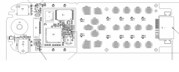
red-display connector ,green-hands-free connector
c)Display part number..
Display connector part number
Hands-Free connector part number
d)Diagnosis-Display is a very fragile component .On this model of phone is a easy operation to change the display. The display is not solder on the PCB but is connected via a display connector. When a phone have no display check first the display connector. Check for dry soldering joints and for oxidation inside of the connector. Check if the flip is in order .If the connector is OK check the display band for interruptions. If lines or columns or columns are missing usually the display have an internal damage.
e)Repair by component change-The display is very easy to change ,pull up the connector flip and pull out the display foil. Then insert a new display foil and push down the flip. The display connector is difficult to change because it is sensible to heat and you have to be very careful when you use the hot air blower ,with circular movements a bit distant from the connector. When you put a new connector in place heat the PCB first with the hot air blower and afrer you solder the connector check the solderings with a soldering iron and finally with a multimetre.
The hands-free connector is easily damaged by humidity and oxidation and by hands-frees that are not compatible with the connector. The connector function as follows :When the hands-free connector is inserted the connector (from the phone) interrupts the headset paths for microphone and speaker and connects the hands-free microphone and speaker..When you pull out the hands-free the process is reversed. Use Kontakt 60 to clean from oxide .Open the phone ,put the multimetre on resistance check and check the microphone &speaker paths when hands-free is inserted (should not be interrupted).With the hands-free inserted check if it is continuity between connector and the hands-free microphone&speaker.
Chapter 6-LED-s and keyboard
a)Faults-Light problems on the display or on the keyboard ,keyboard doesnt function at all or only partially
![]()
![]()
![]()
![]()
![]()
![]()
![]()
![]()
![]()
![]()
![]()
![]()
![]()
![]()
![]()
![]()
![]()
![]() b)Location-
b)Location-
green arrows-keys, red arrows-LED-s
c)LED part number..
d)Diagnosis-The LED-s are organized in partitions with separate power supply from the IC 100.They are linked together I parallel with all the anods on + of the power supply and all the katods on minus. Check the paths between LED-s to see if the paths are interrupted .Put the multimetre on diode check and put the minus on the katode and the plus on the anode and see if a dim light will appear on the LED .If not the LED is damaged (watch the polarity !!).The keys are organized like a matrix. They are organized on lines and columns. Put the multimetre on resistance check and see if the paths on lines (ex.1,2,3) ,or columns (ex. .3,6,9,#) is interrupted. Use Kontakt 60 to clean if oxide is present and finally clean with isopropillic alcohol.
e)Repair by component change-Use the hot air blower to remove faulty LED-s. Replace with new ones .Heat first the board mount with a tweezers the new LED when the board is hot .Avoid to extra heat the leds in order not to melt them.
Level 3
Introduction
Level 3 in repairings means full laboratory repairs. In order to perform theese repairings you need to have experienced technical skills. You need to practice repairings assisted by an experienced technician at least 6 month.Also you need to have advanced knowledge in electronics.This manual was made in order to give you information
that normally is achived in months.This is not a Service factory manual
becouse it will not tell you detailed description of the circuit diagram.For that you can consult service factory manuals and please
feel free to do so.But if you want to know the service problems that our
technicians experienced with this model you can read this manual. You have also a quick photo diagram and a trouble shooting diagram. If you
dont find your fault symtoms in the 1.2,3,4,5check the general information chapter.
The chapters are presented in order of the importance.(Faults number)
a)GSM Processor (ONE-C)
b)RX receiver path (SW 700 diplex filter ,TR 503 ,TR 504,IC 600 RF IC,X600 VCO)
c)TX transmission path (IC 600*,IC 700 TX VCO,TR 702,TR 712,Power Amplifier IC 701,SW 700 switch*) *Underlined components are common for RX and TX paths and will be described in b) paragraph.
d)IC 100 Power IC
e)IC 203 EEPROM,IC 201 FLASH,IC 202 RAM
f)X 300 Stand by Clock 32Mhz,X600 13Mhz Clock, BT 100 clock back up battery.
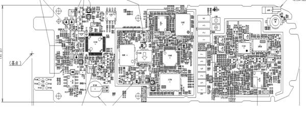
Chapter A- GSM Processor (ONE-C
1.Faults-Phone doesnt power up ,Keys problems, No or low microphone, no or low speaker, no ringing, Check SIM, .No network
![]() 2.Location-
2.Location-
3.IC 100 ONE-C Processor part number
4.Diagnosis-Usually IC 300 have a hard resin underneath so is almost impossible to change it or to solder it on the board. So the IC 300 faults will be 90% fatal. The thing that you can do is to verify the paths from the IC and to heat with the hot air blower but not to much otherwise the solder will enter in liquid state and will cut off the little legs underneath the IC. The IC 100 is a very complex IC and it is practicly a 2 in 1 IC. It is GSM processor and audio baseband converter on the same time.The components that are directly linked to it are:Microphone, Speaker, and Buzzer through TR 350,SIM connector
If you have audio problem (Noisy audio, Low audio,)check the speaker then directly to IC 300
If you have no or low buzzer check (in order)-R327,R328,TR350,D300,IC300
If you have low speaker volume check-C333,IC 300
If you have no speaker check-Visually check the path then with the multimetre ,J 300 (resoldering),IC300
If you have a Check SIM problem check-J600,then directly to IC 300
I include the power on problem here because it is a complex problem and it have on the highest level of diagnosis IC 300 responsible .Here are all the problems I found .Please note the instrument the most useful here is the DC power supply because it provides you a very useful information: The consumption of the phone.
If phone display Test Mode when battery connected check R148
If consumption is 15mAh when you push the power button check X600
If consumption is 30mAh download SW or change IC 201
If no consumption Check L603 and the battery contacts.
Consumption at 60mAh check IC 300
If the phone have short autonomy and consume is high up to 150-200mAh check IC701
No power on and no check battery displayed when ACDC connected download SW(software)
No 2.8V present on C114 and no power check TR 100
No power on and the phone display Contact Provider-Download SW or change IC201 and IC203 and re-download software
If the phone turns on only in test mode check-R148,R147,IC203,IC201
5.Repair by component change-Please call me if someone can do that 0744344454
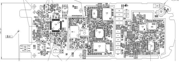
Chapter B RX receiver path (SW 700 diplex filter ,TR 503 ,TR 504,IC 600 RF IC,X600 VCO)
1.Faults-Phone have no network or weak network
![]()
![]()
![]()
![]()
![]() 2.Location-
2.Location-
red-SW700,green-TR503,TR504,blue IC600,yellow-X600
3)SW700-part number..
TR503,TR504-part number..
IC600-part number
X600-part number.
4)Diagnosis-Any of these components plus the paths between them could be defective when the phone have no network or weak network .So when a phone have no network or weak network check (by changing) the following components (in order):SW700 Swich,FL504(900Mhz),FL501(1800Mhz),with multimetre on diode check :TR504 (900Mhz),TR503(1800Mhz),FL503(900Mhz),FL502(1800Mhz),IC600.You could also measure the signal path with oscilloscope and RF generator but it is not a fast service operation.
Here some of the GSM tester faults for RX:
RX level DCS too low-15Db looses instead of 2db-check the SW700
No service GSM-change TR504
No service GSM-checkSW700
No service GSM&DCS check IC 600
No service GSM&DCS IC 700
5)Repair by component change-Use the hot air blower to change the components. There are no components very sensible to heat but pay attention to the IC701 it has real close pins and to IC 700 because it has metallic shielding and hybrid components inside.
Chapter C- TX transmission path (IC 600*,IC 700 TX VCO,TR 702,TR 712,Power Amplifier IC 701,SW 700 switch*) *Underlined components are common for RX and TX paths and will be described in b) paragraph.
1.Faults-Phone cannot make a call
![]()
![]()
![]()
![]()
![]()
![]() 2.Location-
2.Location-
![]()
![]()
 red-Power amplifier-IC701,green
SW700,blue-TR702,TR712,violet-IC700,orange-IC600
red-Power amplifier-IC701,green
SW700,blue-TR702,TR712,violet-IC700,orange-IC600
4)Diagnosis-TX components means that there are components that are involved in transmission task. Some of them such as SW700 and IC600 are complex IC-s or hybrids IC-s that are involved in both tasks reception and transmission. So if the phone have a transmission problem check the following components (in order):IC600,TX VCO IC 700 ,use the multimeter on diode check,TR702(900Mhz),TR712(1800Mhz),IC701(Power Amplifier),Z701(directional coupler 900Mhz),Z700(directional coupler 1800Mhz),SW 700 Switch diplexer,J400(antenna connector).
The power control of the transceiver (power stages or levels) is on 900Mhz-TX VCO IC700 > TR702 > DUAL PA IC 701
1800Mhz-TX VCO IC700 > TR 712 > Dual PA IC 701
So if you have on the Tester diagnosis power levels FAIL focus on these components.
Here are some of the GSM tester diagnosis faults:
Bit error 5.5%GSM-change L511
Bit error 12% change FL504
Phase error DCS too high check IC700,IC600
TCXO is no good (VCO frequency)(bad spectrum) X600
TX is too low in test mode or it isnt at all consumption is higher then 300mAh,IC701 is hot-change IC701
5)Repair by component change-There are no components extra sensible to heat but pay attention at the components that have metallic shield and hybrid components. Grab the component with the tweezers from the main support not from the metallic shield.
Chapter-D IC 100 Power IC
1.Faults-Phone doesnt power on, Phone not charging, phone not communicate with the test equipment
2.Location
![]()
3.Part number IC100
4.Diagnosis-The IC 100 task is to power supply all the stages in the phone and to control the charging process. If the phone consumes less then 15mAh when push the power button and the SW (software) is all right the X600 is not damaged or defective then the next component to check is IC 100.The charge process is as follows
Pre charge: The IC100 verify if the temperature and the voltage of the battery is normal. If not the IC100 command trickle charge 52mAh
When the battery enter in normal state (temperature and voltage) IC100 command rapid charge 420mAh.If batt. Temperature becomes abnormal IC100 cut the charging current at 21mAh.Then again when the temp is normal rapid charge begin. When full charge is detected by IC100 again cut the charging current to 21mAh until you interrupt the charging .This continous low charging prevent the battery to descharge. So the IC 600 control the charging by 2 detectors :temperature by a thermistor inside the battery and by voltage measurement. Thermistor connectings are on the interior pads of the battery and voltage connectors (main power supply is on the exterior pads. If the interior pads are not making contact with the battery connector J101 then the phone display Invalid battery.
Here some of the faults that you can meet
Charging problem-60 to 100mAh current ,no charging display VBATT 4.8V instead of 1v with charging cable and without battery-Check IC 100
Or 70 to 80mAh and 2.5v VBATT-check IC100
No charging visual check-connector J103 broken
Phone doesnt charge properly the battery-72 to 155mAh-check TR106,TR107,R128,R129
Charging consumption 850mAh instead of 420mAh-chack TR106,TR103,D118.
Not charging and display Low battery and consumes 180mAh-check R120,R121,TR
Not charging display test mode and consumes 25mAh-check-
D125,Tr106
Display full battery in few seconds-check-R121,TR106
3.6V charging voltage instead of 5V in charging-check D117
No service-TX is good in test mode ,RX level is good, and IC 600 changed-check IC300
5.Repair by component change-IC 100 is fare easy to change IC .Anyway you need to practice before do that .Use the hot air blower to remove faulty component and place another one in place and resolder
Chapter E- IC 203 EEPROM,IC 201 FLASH,IC 202 RAM
1.Faults-No power, Contact Provider, SW Problems
2.Location-
![]()
![]()
![]()
red-EEPROM, green-FLASH, blue-RAM
3.EEPROM-IC203,FLASH-IC201,RAM-IC202
4.Diagnosis-These components could have 2 faults SW (software) problems that can be solved by programming the components and physical problems that can be solved by component change. First try to connect phone to ACDC without battery. If the phone doesnt display check battery download SW .If the phone display contact provider download SW. Usually if a phone have software problems it consumes when you push power button around 30mAh.If you cant download SW or the download is interrupted during data transfer change the component (EEPROM or FLASH).
5.Repair by component change-The most difficult component to change is the FLASH because it is not a regular BGA component but a glass one .The RAM and the EEPROM are not rising problems. Use the hot air blower to remove faulty components and to mount new ones in place.
Chapter-F- X 300 Stand by Clock 32Mhz,X600 13Mhz Clock, BT 100 clock back up battery.
1.Faults-No power ,no network(X600), Clock is not correctly counting the time(X300),when remove the battery and take it off the phone doesnt remember the clock(BT100)
2.Location-
![]()
![]()
![]()

red-X600,green-bt100,blue-X300
3.13Mhz clock (X600) part number.
32Mhz clock (X300) part number..
Back up battery(BT100) part number
4.Diagnosis-The crystal clocks are very sensible to shocks .So if you have a record that the phone suffred a shock check first the crystal oscillating clocks. First check them visually for physical damage ,put them on ear to listen if it is something broken inside. Use the oscilloscope and the GSM tester in fault find to see if the crystals are oscillating properly. The back up battery(BT100)is sensible to oxide and humidity. And it is also sensible to heat. After one year of service its capacity is strongly decreasing.
5.Repair by component change-Use the hot air blower to change the clocks .Avoid using too much heat otherwise the clocks will be damaged .Pay extra attention if they have plastic case. Do not use the hot air blower to change the BT100 battery .It will explode if heat is applied on it.
Seni Dragos
|
Politica de confidentialitate | Termeni si conditii de utilizare |

Vizualizari: 1674
Importanta: ![]()
Termeni si conditii de utilizare | Contact
© SCRIGROUP 2025 . All rights reserved