| CATEGORII DOCUMENTE |
| Bulgara | Ceha slovaca | Croata | Engleza | Estona | Finlandeza | Franceza |
| Germana | Italiana | Letona | Lituaniana | Maghiara | Olandeza | Poloneza |
| Sarba | Slovena | Spaniola | Suedeza | Turca | Ucraineana |
Frequency Division Multiplexing
OFDM Basic Principles 3
Other OFDM Systems10.
Benefits of OFDM and Performance Criteria12
Digital Audio Broadcasting An Application of OFDM . 17
Other Developments .20
References . 21
Orthogonal Frequency Division Multiplexing (OFDM) is a multicarrier transmission technique used in applications catering to both Wired and Wireless Communications. However, in the wired case, the usage of the term Discrete Multi-Tone is more appropriate. The OFDM technique divides the frequency spectrum available into many closely spaced carriers, which are individually modulated by low-rate data streams. In this sense, OFDM is similar to FDMA (The bandwidth is divided into many channels, so that, in a multi-user environment, each channel is allocated to a user). However, the difference lies in the fact that the carriers chosen in OFDM are much more closely spaced than in FDMA (1kHz in OFDM as opposed to about 30kHz in FDMA), thereby increasing its spectral usage efficiency. The orthogonality between the carriers is what facilitates the close spacing of carriers.
The orthogonality principle essentially implies that each carrier has a null at the center frequency of each of the other carriers in the system while also maintaining an integer number of cycles over a symbol period.
The motivation for using OFDM techniques over TDMA techniques is twofold. First, TDMA limits the total number of users that can be sent efficiently over a channel. In addition, since the symbol rate of each channel is high, problems with multipath delay spread invariably occur. In stark contrast, each carrier in an OFDM signal has a very narrow bandwidth (i.e. 1 kHz); thus the resulting symbol rate is low. This results in the signal having a high degree of tolerance to multipath delay spread, as the delay spread must be very log to cause significant inter-symbol interference (e.g. > 500usec).
Orthogonality
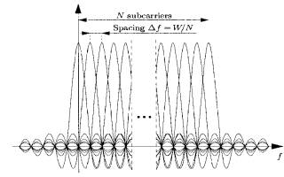
To generate OFDM signals successfully the relationship between all carriers
must be carefully controlled in order to maintain orthogonality. Shown below is
the frequency spectrum depicting the various carriers/channels (used
interchangeably). Rectangular windowing of transmitted pulses results in a
sinc-shaped frequency response for each channel. As can be seen, whenever any
particular carrier frequency attains peak amplitude, the remaining carriers
have a null point.
Fig. Frequency spectrum showing N channels for an OFDM system with N carriers over a bandwidth W
The spectrum required is first chosen based on the input data and the modulation scheme used (typically Differential BPSK, QPSK or QAM). Data to be transmitted is assigned to each carrier that is to be produced. Amplitudes and phases of the carriers are calculated based on the chosen scheme of modulation. The required spectrum is then converted back to its time domain signal by employing Inverse Fourier Transform algorithms like the Inverse Fast Fourier Transform (Cooley-Tukey Algorithm)
The next step is that of adding a guard period to the symbol to be transmitted. This ensures robustness against multipath delay spread. This step can be achieved by having a long symbol period, which minimizes intersymbol interference. The level of robustness can be further increased by the addition of a guard period between successive symbols. The most popular and effective method of doing this, is the addition of a cyclic prefix. A cyclic prefix is a copy of the last part of the OFDM symbol, which is prepended to the transmitted symbol. This makes the transmitted signal periodic and does not affect the orthogonality of the carriers. Further, this also plays a decisive role in avoiding inter-symbol and inter-carrier interference.
Fig. The Cyclic Prefix is a copy of the last part of the OFDM signal
A cyclic prefix does however introduce a loss in the signal-to-noise ratio, but this effect is usually negligible as compared to its effect on mitigating interference.
A schematic diagram is shown next and a mathematical model of a base band OFDM system is now developed.
Fig. Base band OFDM system Model
Since the first OFDM systems did not use digital modulation and demodulation schemes, the continuous-time OFDM model shown above can be considered as the ideal OFDM system. To build the mathematical model, we start with the waveforms used in the transmitter and proceed all the way to the receiver.
We assume an OFDM system with N carriers, a bandwidth of W Hz and a symbol length of T seconds, of which Tcp seconds is the length of the cyclic prefix. The transmitter uses the following waveforms:
= 0 otherwise .Eqn. 1
where T = (N/W) + Tcp .
A note must also be made of the fact that fk(t) = fk(t + N/W) when t is within the cyclic prefix. Since fk(t) is a rectangular pulse modulated on the carrier frequency kW/N, the common interpretation of OFDM is that it uses N carriers, each carrying a low bit-rate. The waveforms fk(t) are used in the modulation and the transmitted base band signal for OFDM symbol number l is
![]() ..Eqn.
2
..Eqn.
2
where x0,l, x1,l,xN-1,l are complex numbers obtained from a set of signal constellation points. When an infinite sequence of OFDM symbols is transmitted, the output from the transmitter is a juxtaposition of individual OFDM symbols:
![]() Eqn.3
Eqn.3
An important assumption is that the effect of the impulse response of the physical channel (which may or may not be time invariant), is restricted to the time period
t I [0,Tcp], i.e. to the length of the cyclic prefix. The received signal then becomes :
.Eqn.
4
where n(t) is additive, white and complex Gaussian noise.
We now move on to the receiver.
A filter bank, matched to the last part [Tcp,T] of the transmitter waveforms Φk(t), i.e. ,
![]() Eqn. 5
Eqn. 5
= 0 otherwise
This operation effectively removes the cyclic prefix in the receiver stage of the system. All the ISI is contained in the Cyclic Prefix and does not manifest itself in the sampled output obtained at the receiver filterbank. We can now remove the time index, l, when calculating the sampled output at the kth matched filter.
![]() Eqn.6
Eqn.6
Considering the channel to be fixed over the OFDM symbol interval and denoting it by g(τ), Eqn.6, after simplification gives us the following result:
![]() Eqn.7
Eqn.7
where G(f) is the Fourier transform of g(τ) and nk is additive white Gaussian noise.
We move on next to the Discrete Time Model for the OFDM system
The modulation and demodulation (with Φk(t) & ψk(t)) in the continuous-time model are replaced by the Inverse Discrete Fourier Transform and the Discrete Fourier transform respectively while the channel is a Discrete-Time convolution. The Cyclic Prefix operates in the same way in this system and calculations are essentially performed in the same fashion. As in all other cases, the integrals are changed to summations when in the Discrete-Time domain. An end-to-end discrete-time model is shown below:
Fig. Discrete-Time OFDM System
The employment of a cyclic prefix longer in duration than the channel, transforms the linear convolution into a cyclic convolution, when seen from the receiver end of the system. Denoting the cyclic convolution by * , we can depict the whole OFDM system by the following equation :
yl = DFT(IDFT(xl) * gl + nl) = DFT(IDFT(xl) * gl) + nl .Eqn.8
where yl contains the N received data points, xl the N transmitted constellation points, g, the channel impulse response (padded with zeroes to obtain a length, N) and nl, the channel noise. Since the channel noise is assumed to be white and Gaussian, the term, nl=DFT(nl) represents uncorrelated Gaussian noise. Using the result that the DFT of two cyclically convolved signals is equivalent to the product of their individual DFTs, we obtain
yl = xl . DFT(gl) + nl = xl . hl + nl Eqn.9
where the symbol . denotes element-by-element multiplication.
While describing OFDM systems in the previous sections certain assumptions were made. These have been listed below:
A Cyclic Prefix is used
The impulse response of the channel is shorter than the Cyclic Prefix
Since fading effects are slow enough, the channel is considered time-invariant over the symbol interval
Rectangular Windowing of the transmitted pulses
Transmitter and Receiver are in perfect synchronism
Channel noise is additive, white, and complex Gaussian
Also worth mentioning is the fact that the transmitted energy increases with an increase in the duration of the Cyclic Prefix, while the expressions for received and sampled signals stay the same. The transmitted energy per carrier is given by
![]() ..Eqn.10
..Eqn.10
and the SNR loss because of the discarded Cyclic Prefix in the receiver becomes
SNRloss = -10 log10(1- γ) ..Eqn.11
where γ = Tcp/T is the relative length of the Cyclic Prefix. Therefore, a longer Cyclic Prefix would mean a higher SNR loss. Typically, the relative length of the Cyclic Prefix is small and the ICI- and ISI- free transmission motivates the usage of OFDM , the SNR loss being less than 1 dB for γ<0.2.
Depending on the channel characteristics and desired complexity of the synchronization circuitry in the receiver we could design certain other OFDM systems.
Case 1 : If the Channel response is bad and increasing the length of the Cyclic Prefix makes the SNR loss a substantial quantity, we can resort to adding a guard time interval between symbols. The Guard Period is characterised by a zero transmission, i.e., transmitting silence. This scheme also has another advantage. It might help simplifying synchronization circuitry. Simple envelope detection might be enough because of the presence of the guard period
Case 2 : The power spectrum of the OFDM system decays as f-2 since we were using a rectangular window for the transmitted pulses. In certain cases, this may not be good enough and methods have been proposed to shape the spectrum. Shown below is the spectrum where a raised cosine pulse is used. In this case the roll off region also acts as a guard space. If the flat part is the OFDM symbol, including the cyclic prefix, both ICI and ISI are avoided. The spectrum with this kind of pulse shaping is shown further below, where it is compared with a rectangular pulse. It is easily seen that this kind of spectrum falls much more quickly and reduces the interference to adjacent bands.
avavavavavav
Other types of pulse shaping such as overlapped and
well-localized pulses have also been investigated.
Amplitude
time
Fig. Puldse Shaping using Raised Cosine Fig. Normalised Spectrum with Rectangular
Grey indicates the part including CP and signal -pulse(solid) and raised-cosine(dashed)
The four main criteria for evaluating the performance of the OFDM system are tolerance to multipath delay spread, peak power clipping, channel noise and time synchronization errors. The performance of different OFDM systems under varied channel conditions, keeping in mind the above criteria is now discussed.
Multipath delay Spread Immunity
In a MATLAB simulation of a practical OFDM system modeled by Eric Lawrey [2], the following assumptions were made:
Carrier Modulation Used: DBPSK, DQPSK or D16PSK
FFT Size : 2048
Number of Carriers Used : 800
Guard Time: 512 samples (25%)
Guard Period Type: Half Zero, Half a cyclic extension of the symbol
Note: A point to note here would be that most OFDM systems in effect are COFDM (C=Coded), meaning, Forward Error Correction is applied to the OFDM signal. Typically, an 800 carrier system would allow a maximum of 100 users to operate. Each user is allocated 8 carriers so that even if some carriers are lost due to frequency selective fading, the rest will allow the lost data to be recvered using the error correction scheme.
It was found that a delay spread of 256 samples (corresponding to approximately 80milliseconds) occurred only if it was assumed that a reflection that traveled 24km extra path length suffered only a 3dB attenuation. As can be seen from the BER v/s Multipath Delay Spread curve, there is little or no delay associated with reflections that reached the receiver within the lifetime of the guard period. The Delay Spread increases rapidly only after the guard period has ended (due to ISI). However, if a signal is attenuated by more than the noise tolerance of the OFDM signal, no significant effect will occur on the BER.
The maximum BER occurs when the delay spread is longer than the symbol interval itself. Such a case would definitely increase the Inter Symbol Interference.
Peak Power Clipping:
The OFDM signal showed high degrees of tolerance (BER is not affected adversely) even if it was heavily clipped. The clipping distortions mostly arise from the Power Amplifier transmitting the signal. The signal can be clipped by as high as 9dB without a significant effect on the BER. This could be used to our advantage, meaning, the OFDM signal could be clipped by up to 6dB so that the Peak-to-RMS ratio can be reduced, thus alowing an increased transmitted power.
Gaussian Noise Tolerance of OFDM:
Since the transmitted signal is similar to standard FDM, it is found that the SNR performance is similar to standard single carrier digital transmission. The BER is found to be adversely affected, if the SNR drops below 6dB. The SNR tolerance is mostly dependant on the kind of modulation used (i.e. QPSK, BPSK, 16PSK etc.) as shown in the plot.
Time-Synchronization Errors
The Synchronization factor in an OFDM system is the most critical one. When the receiver is initially turned on, it is not in synchronization with the transmitter. For this reason, data transmission in an OFDM system might need data to be sent in frames. At the beginning of each frame a null symbol is transmitted, so that the receiver can detect incoming data using simple envelope detection techniques. However, the noise in the signal might interfere with the envelope detection process. In general, it has been found that the receiver synchronizes itself with the transmitter in a time interval less than or equal to the guard interval.
fig. Shows a block diagram representation of the DAB system
DAB is a means of providing current AM & FM listeners with a new service that offers :
Improved sound quality (CD comparable)
Increased service availability, especially reception in moving vehicles
Flexible coverage scenarios
High Spectrum Efficiency
As can be seen in the block diagram, the source (Music etc.) is encoded using the MPEG Layer-II Audio standards and is broadcast using COFDM. The Eureka-147 DAB signal consists of multiple carriers assembled using COFDM within a 1.536 MHz channel bandwidth. Four possible modes of operation define the channel coding configuration, specifying the total number of carriers, the carrier spacing and also the guard interval duration. Each channel provides a raw data rate of 2304 Kbps; after error protection, a useful data rate, anywhere between 600 to 1800 Kbps is available to the service provider, depending on the user-specified multiplex configuration. This useful data rate can be divided into a large number of possible configurations of audio and data programs.
The more interesting issue(in the context of this paper) is the implementation of the COFDM system. Though there are several processing stages required to generate and receive an OFDM signal, the most processing intensive stage are the ones in which the Fast Fourier Transform or its Inverse transform are implemented.
The complexity of performing an FFT is dependent on the size of the FFT. However, it can be seen that because the symbol period increases with a larger FFT, the extra processing required is minimal. For e.g. the 2048-point FFT requires only 1.1 times the time required for processing a 1024-point FFT. To get an estimate of the processing power required to implement a practical phone system, lets consider an example.
Given Data:
Total bandwidth : 1.25 Mhz
User capacity : 64 Users
Carriers per User: 13
Modulation Used : QPSK
FFT Size : 2048
No.of complex calculations required for a 2048-pt. FFT : 33792
Guard Period : 512 samples
From the above data we can compute

No. of Active carriers : 832
Data Rate of each user : 39 Kbps
Useful Symbol time : 666 msecs
Total Symbol time : 833 msecs
The maximum time that can be taken in performing the calculations is once every symbol, thus once every 833 msecs. Now, if we assume, the processor requires 2 instructions to perform a single complex calculation, and there is an overhead of 30% for scheduling of tasks and other processing. The minimum processing power of the DSP being used, must then be MIPS = (33792 x 2 x 1.3 x 10-6)/(833 x 10-6)=105
Since a transmitter requires a minimum of 105 MIPS, a transceiver would definitely require a minimum of 210 MIPS. DSPs that are lesser priced do not have such processing capabilities (e.g. ADSP-2185L is 40MIPS).
The DAB system uses the Texas Instruments DSP TMS-320C62x family of processors. These are 16/32-bit fixed point processors valued between $25 to $180. The processing capabilities of these processors are around 1200 MIPS.
The history of OFDM dates back to the mid 60s when Chang published his paper on the synthesis of bandlimited signals for multichannel transmission. Shortly after Chang presented his paper, Saltzberg performed an analysis of the performance, where he concluded that the strategy should concentrate more on reducing cross talk between adjacent channels than on perfecting the channels. A major contribution was made in 1971, by Weinstein and Ebert. They used the DFT to perform baseband modulation and demodulation. Thereafter Peled and Ruiz introduced the concept of the Cyclic Prefix in 1980.
Currently, work is on in the following fields among others :
Algorithms to reduce Peak to Average Power Ratio in multicarrier communication systems
Coding strategies for OFDM with antenna diversity for high Bit-Rate Mobile data Applications
Multiuser Subcarrier Allocation for OFDM using Adaptive Modulation
Fading and carrier frequency Offset Robustness for different Pulse Shaping Filters in OFDM
Ove Edfors, Magnus Sandell, Jan-Jaap van
de Beek, Daniel Landstrom, Frank Sjoberg An
Introduction to orthogonal frequency division multiplexing
Eric Lawrey The suitability of OFDM as a modulation technique for wireless
communication, with a CDMA comparison
Knud Knudsen, Bob Heise, Mohsen
Hosseinian , Michael Fattouche A 26 Mbps
OFDM Transceiver Wi-LAN Inc.,
Adrian Bohdanowicz, Chris van den Bos, Maarten Ditzel, Wouter A. Serdijn, Gerard J.M. Janssen, Ed. F.A. Deprettere Wireless Link using OFDM Modulation: Performance prediction, Modeling and Implementation
Michael Speth OFDM Receivers for Broadband Transmission
Radio Broadcast Technologies Research
division of the Communications Research Centre (CRC),
Texas Instruments ETS 300 401 DSP DAB modulator www.ti.com
|
Politica de confidentialitate | Termeni si conditii de utilizare |

Vizualizari: 2366
Importanta: ![]()
Termeni si conditii de utilizare | Contact
© SCRIGROUP 2025 . All rights reserved