| CATEGORII DOCUMENTE |
| Bulgara | Ceha slovaca | Croata | Engleza | Estona | Finlandeza | Franceza |
| Germana | Italiana | Letona | Lituaniana | Maghiara | Olandeza | Poloneza |
| Sarba | Slovena | Spaniola | Suedeza | Turca | Ucraineana |

|
Homebrew 10' Wind Turbine, METAL WORK, part 2
Questions or comments? Click here to send us an email at our new email address.!2000 by FORCEFIELD
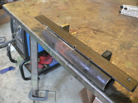
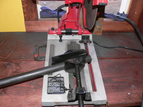
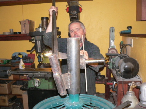
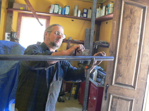
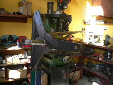
The main chassis for the wind turbine is finished, so at this point the tail boom needs to be fabricated. The tail bearing hangs/pivots on the the tail pivot which is welded to the frame of the wind turbine. The pivot was attached to the yaw bearing via an angled bracket. The bearing is made from 1.25' sched 40 pipe. It's the same length as the pivot (9'). It needs to be notched so that it can fit over the 1' pipe we used for the pivot, and the notch will fit over the bracket that attaches the pivot to the yaw bearing. One side of the notch will serve as a stop to hold the tail in its proper position. Pictured above we're preparing to notch the tail bearing with a cutting torch. Two of the 1' x 2' magnets stuck to the back of a piece of angle iron makes for a nice jig/template to help do a neat job. Again, the tail bearing is made from 1.25' sched. 40 pipe, it's 9' long. Cut the notch half way up the pipe (so 4.5' is notched, and 4.5' is left undisturbed).
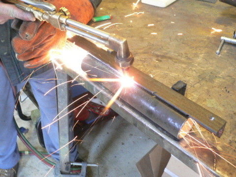
Pictured above George is cutting one side of the notch using the angle iron to help guide the torch. Once that sides cut we turn it about 160 deg and cut the other side of the notch. We say to notch out about 160 deg. This is the maximum width that you should make the notch, in most cases you could make it narrower (120 - 140 deg is usually fine) - so this is not critical. If the notch is too narrow then the tail may not be able to fully furl. This depends on the width of the notch and also the thickness of the welds which attach the tail pivot to the tail bracket. Once both sides of the notch are cut, you can cut between the lines and finish the notch. Save the scrap, you'll need it later.
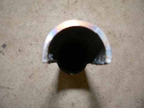
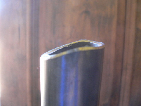
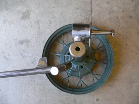
Shown in the picture is how the tail bearing should look after it's notched looking up at it from the bottom. There are are plenty of other ways to do this. If a cutting torch is n ot available, this notch is easy to make with a jig saw, hack saw - band saw etc there are lots of different ways to do things. A milling machine does nicely too, but it leaves kind of a small scrap (the piece that comes out of the notch) and we do need the scrap. I prefer to have the scrap larger and save time so a bandsaw or torch is preferable.
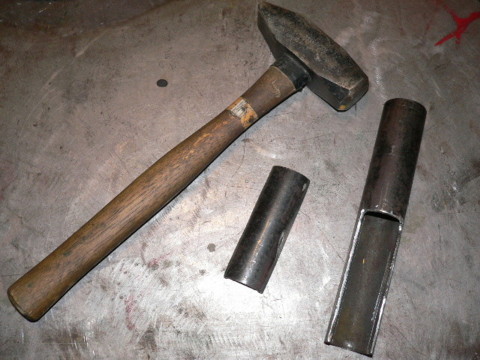
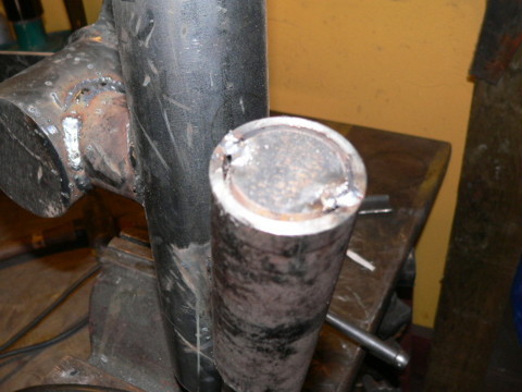
Shown above is the notched tail bearing and the scrap you cut out. Use a hammer and beat the scrap a bit flatter so that it's inner diameter fits nicely around the outer diameter of the tail bearing.
Put the tail bearing on the machine and tack weld a 1' diameter plug (it could be up to 1.25' diameter) in the top of the tail bearing. It needs to fit down inside the tail bearing so that the top of the plug is flush with the top of the pipe.
Turn the tail bearing all the way counter clockwise so that it comes to stop against the notch on the side opposite that shown in the picture. (one side of the notch needs to come up against the tail bracket, this is the tails 'normal/unfurled' position)
Tack weld the scrap from cutting the tail bearing notch on the other side (the side opposite the alternator) of the tail bearing as shown above. This serves as a reinforcement should the tail come slamming down from the furled position back into the normal position. It'll help keep the notched tail bearing from getting bent or cracking around the notch.
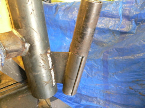
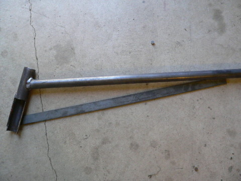
The tail boom is fabricated from 1' shed. 40 pipe, it's 5' long. You need to cope one end of it so that it fits against the tail bearing. The angle between the tail bearing and the tail boom should be about 20 degrees. Pictured above we're cutting a 20 deg angle through half the pipe (leaving the other half cut at 90 deg) - kind of a quick/cheap way to cope the pipe so it fits the tail bearing.
Thats the finished cut on the tail boom. This will fit nicely against the tail bearing for welding.
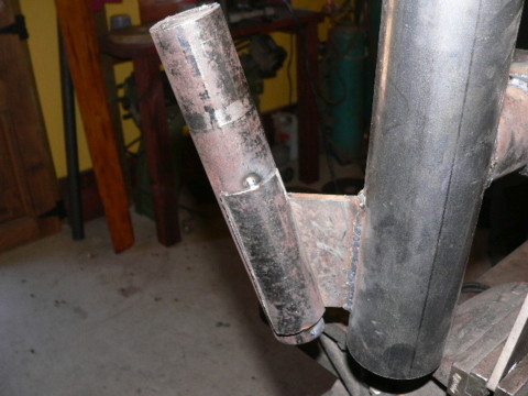
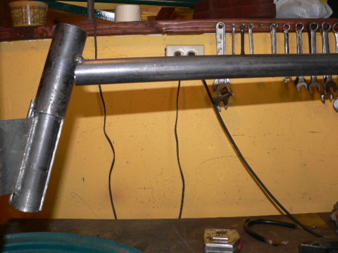
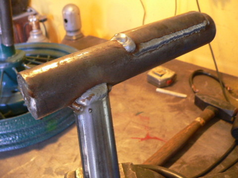
Thats how it should look from the side. There's about a 110 deg angle between the tail pivot and the tail boom. Its a common mistake for folks to weld the tail boom at 90 deg to the tail pivot. The end result will be a tail that points down and looks funny (itll work that way but it looks funny). I prefer to have the tail pointing upwards a couple degrees.
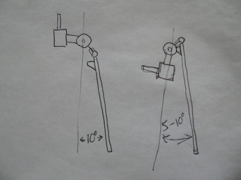
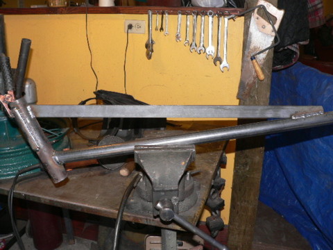
That's how it should be from the top. When the tail is in it's position of rest (the normal running position, turned all the way counterclockwise as far as it will go) it should be about 10 deg to the left from parallel with the wind (parallel with the spindle). Get someone to hold the tail so that it's in the right position as shown in the two pictures above and tack weld it there. Weld it so that you can look at it - and still bend things around a bit if necessary. The reason the tail is sticking out at an angle about 10 deg out of parallel with the wind direction is to compensate for the fact that the alternator sticks out 5' on the opposite side. When the wind is pushing against the blades/alternator there is a force trying to turn the whole machine counter clockwise (assuming you're looking down at the machine) The tail is angle slightly to the other side to help counteract this force. That said, it's important to keep in mind that wind turbine blades when running at speed *want* to run square with the wind. In our experience the 10 deg angle in the tail is not critical, anything between 5 - 15 degrees should work fine. Like most things with this design, it's not worth fretting a great deal over getting things perfect. If you're a couple degrees off it won't matter.
Then finish all the welds.
Make a gusset 30' long from 1.25' x .25' bar stock. Cut it to length (30') then lay it under the tail so you can mark where it needs to be cut with a soap stone. Then we cut it with a torch or a bandsaw so it fits well. This gusset probably isn't needed if the tail is welded to the tail bearing well - but it looks nice and adds some insurance. The 30' length is not critical.
Weld the gusset onto the tail boom.
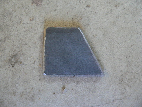
This is the 'stop' (or bumper) that you need to fabricate, and weld to the tail boom. This will bump against the yaw bearing when the machine is fully furled and make sure you have about a 10 deg angle between the blades and the tail (as shown in the drawing above) and insure that the tail can never hit the blades. The piece shown above is fabricated from 1/4' flat steel. The only critical measurment is the one that stands between the tail boom and the yaw bearing (should be 2' if all the angles are perfect in your machine but slight variations could change this). The one pictured is 2' wide at the bottom, 2' tall, and 1.5' across the top. It's angled on one side only for the sake of appearance.
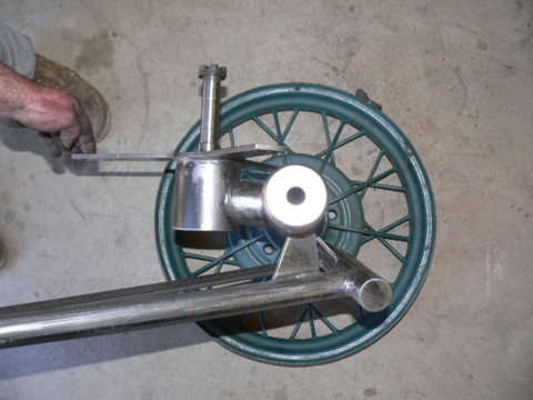
In the picture, George is clamping the bumper in there between the tail boom and the yaw bearing. It's helpful to have someone do this so you can position the part in its proper place (double check that its long enough to keep the tail out of the blades). It should be square with the yaw bearing and fairly well centered on it (the 1.5' long surface touches the yaw bearing on center when the machine is furled). When those two conditions are true - weld it on there.
Theres a picture of it welded on, the tail is sitting in its normal running (unfurled) position.
The image above shows the machine in it's furled position. You can see how the stop comes up against the yaw bearing. Notice the angle between the tail boom and the stator bracket - this same angle will exist between the tail boom and the blades. Setup this way the tail can never come into the blades.
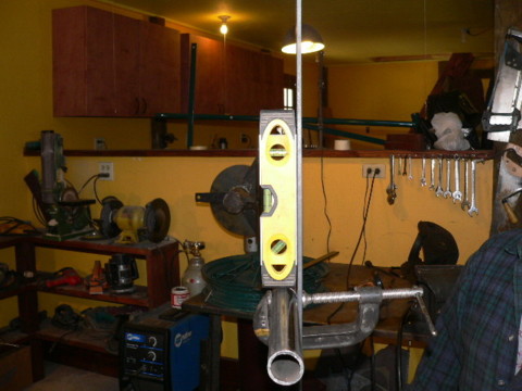
The last metal part to fabricate is the tail vane bracket. Its 34' long made from 1.25' x .25' bar stock, and each end has a 3/8' hole drilled 1' from the end (to hold the wooden tail vane which we've not made yet). Use a square as shown in the picture. Clamp the tail vane bracket square with the tail boom and 9' from the end of the tail boom. Again - none of these measurments are critical, it's just our standard way of doing things. Tail shape is not critical so if you decide to make a different shaped tail for the machine then it will probably make sense to change the dimensions here.
Use a small torpedo level to make sure the bracket is vertical. Once everything seems right tack weld it on there and inspect everything. Since it's tack welded you can still make changes if needed. Once it looks good, weld it permenantly.
Now all the metal work is done save a bit of grinding perhaps to clean up the welds. |
|
Politica de confidentialitate | Termeni si conditii de utilizare |

Vizualizari: 1822
Importanta: ![]()
Termeni si conditii de utilizare | Contact
© SCRIGROUP 2025 . All rights reserved