| CATEGORII DOCUMENTE |
| Arhitectura | Auto | Casa gradina | Constructii | Instalatii | Pomicultura | Silvicultura |
Timber Design
The structure design process is divided into three stages: first the structure geometry and applied loads are defined, then internal forces and displacements are calculated, and finally code requirements are verified and successive structural members are designed. This section of the manual is concerned only with the third stage. We assume here that the load effects in the structure are already calculated. Also please note this section is very similar to the steel design section; therefore, if the reader is familiar with steel design in Robot Millennium, he or she can skim the contents and focus on the differences only. In the current version of Robot Millennium the following timber codes are available: French timber code CB71, Eurocode 5, Eurocode 5 French NAD and Polish timber code PN-B-03150:2000.
User can either verify or design the modeled structure. The design is applied to either single members or groups of members and calculations can be executed in a similar way.
Depending on the selected timber code, the contents of the list can vary, but the basic definitions remain the same no matter which code has been selected.
The following definitions apply:
|
MEMBER |
Single structure member to be verified or modified in the module. The most common bar types are columns, beams. A member used during verification/design can be defined as a single element or a sequence of consecutive elements creating a column, beam, etc. |
|
GROUP |
Member list. A group of structural members for which the same section is assigned. Once the verification/design is completed, a section appropriate for all members in the group (regardless of differences in internal force values for these members or design parameters) will be selected. Groups are defined in order to limit the variety of sections in the designed structure. |
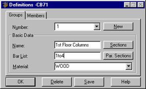
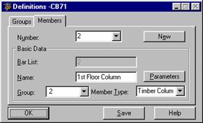
Once the TIMBER DESIGN layout is selected, the screen will be divided into three parts: graphic viewer for structure presentation and two dialog boxes: Definition and Calculations
The Definition dialog box contains two tabs: Groups and Members (see the pictures below). Once the members and groups are defined, verification for a single member or a group will be carried out. Clicking on the Parameters button located on the Members tab results in opening the Parameters dialog box (the contents of which depend on the selected timber code available in Robot i.e. either Eurocode5 or French timber code CB71). The basic set of code parameters includes buckling length, buckling parameters, lateral-buckling parameters, rigidity, fire resistance parameters, etc.
Among the interesting options to be found in Robot, one can count the possibility of automatic design by means of parameterized tapered sections. The option is available by pressing the Parameterized sections button located in the Definitions dialog box (see section 6.1).
|
|
|
The name of the selected bar is given in the Member Type field. The bar length may be entered in the Member Length ly or lz fields. This may be done in two ways:
once the Real option is selected, the entered value is interpreted as the length
once the Coefficient option is chosen, the value is interpreted as the coefficient by which the actual value should be multiplied to obtain the appropriate length. For example entering a 0.25 value means that the appropriate length is equal to 1/4 of the actual length.
For a simultaneous definition of several members of differing actual lengths, e.g. additional supports equally spaced, the second method mentioned is very convenient. If the set parameters are to be saved as a category, entering the length this way is essential. The buckling length coefficient depends on the end support condition of the bar nodes in the buckling plane. The buckling length may also be defined in the Buckling Scheme dialog box opened by pressing the icon representing the selected buckling model type. Typical schemes are found here; once one is selected, the coefficient value will be accepted or calculated automatically.
The buckling is always considered in the calculations if a compression force appears in the member even if it is negligible in comparison to the other internal forces. The program does not perform analysis determining if buckling effects should be disregarded or not on its own. If the user wants to eliminate buckling effects from the calculations, the last icon must be chosen. It represents the option to disregard buckling in the calculation process.
Options used during the lateral buckling verification: lateral buckling type, load level, and lateral buckling coefficient for lower and upper flanges.
After pressing the Other button, the screen shows a dialog box used for defining parameters for the additional check of members subjected to bending.
The options given in the dialog box above enable running additional checks for particular beams subjected to bending in compliance with the requirements described in the EC5 code
The regulations given in point 5.2.3 of EC5 code apply to variable inertia beams inclined to one side (case 1). The remaining cases concern beams made of glued timber, for which the additional check is carried out in conformity with point 5.2.4.
Additional verification of beams subjected to bending takes place once the option Additional verification for elements subjected to bending is switched on. After selecting one of the 4 beam types, beam parameters needed for calculations should be defined in the available edit fields. To check the beams subjected to bending, the user may define parameters as follows (a number of parameters available depends on the beam type):
angle - angle of inclination of the beam top surface to the horizontal plane
radius - fillet radius of the axis of the arc-shaped beams
Hap - height of the beam section at the midpoint of its length
thickness - thickness of a single laminate layer
Kvol - coefficient depending on the beam volume; the value of this coefficient is determined according to point 5.2.4.(5) from the formula Kvol = (Vo/V)^0.2, where Vo - reference volume = 0.01 m3, whereas V = 2Vb/3, where Vb - volume of the entire beam.
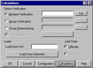
In the dialog box presented below, calculation options for timber members or groups of members are to be selected.
The Option of Verification field allows the user to select:
|
Member Verification - verification according to the member list based on consecutive and independent calculations for each member. The procedure is based on considering intermediate points on a member along with the load case present, verifying that it is suitable by checking against the worst case scenario according to the relevant codes of practice. A number of points are considered during calculations and a list of load cases is specified. In other words, verification is based on examining whether certain sections (accepted before internal force calculations) meet the code requirements. Such selection determines whether the member will be considered satisfactory, unsatisfactory or unstable. |
|
Group Verification - group verification is based on consecutive and independent calculations (see Member Verification) for each member in the group. Material properties set for the group are taken into account.
Group Design - group design is based on examining the previously adopted set of sections determined by Group Definition and eliminating those that do not meet the code requirements. Consecutive sections are eliminated until the first section meeting the requirements is found. The described process is carried out separately for each family of sections belonging to the analyzed group. Code calculations are performed for each section at consecutive intermediate points on the member, consecutive load cases, consecutive elements of the given member and all members belonging to the group. If the given section does not meet the code requirements for a certain intermediate point, the load case or element of the member in the group is eliminated and the next section from the list is chosen. This process continues until all sections from the list are eliminated. To start calculations in the design mode at least one group has to be defined. Design may be carried out for many groups in which case the described process is run for each group separately.
The lower part of the dialog box contains two fields: Loads and Limit State. In the first one, the following options are located:
load case list - field for displaying the load cases taken into account during calculations. The load case number can be entered therein.
load case selection - opens an additional dialog box (Case Selection) in which load cases to be considered during calculations can be chosen.
Calculations can be run for ULS and SLS.
Clicking on the Calculations button results in timber member verification or design, according to the parameters set in the Definition and Calculations dialog boxes. Once the calculations are completed, the Simplified Results dialog box will be displayed on the screen. Clicking on the section shown in the short list will result in displaying the Results dialog box.
Similarly as for steel members, the detailed analysis is also available for timber members; it can be activated by pressing the Detailed button provided in the Detailed results dialog box for EC5 code. The program enables performing additional calculations based on the requirements described in Eurocode 5:
with transversal compression considered (coefficient Kc,90)
with openings considered (coefficient Khol: see: Eurocode 5:Book1 IV-5-8)
with the shape of a beam ending considered (coefficient Kv: see Eurocode:Book1 IV-5-7).
Each of the member analyses listed is performed independently, thus each of them may be run separately.
Calculations can be also carried out for user-defined section forces (not calculated by the program itself). This can be done using the Manual Calculations option that is available from the Timber Member Design menu. Member verification/design can be carried out.
Configuration button allows for selecting a number of points at which a member is calculated. These
points are chosen equidistant along the member.
SELECTED REFERENCES (DESIGN OF TIMBER STRUCTURES)
EUROCODE 5 - Calcul des structures en bois. Partie 1-1: Regles generales et regles pour les batiments. Norme P21-711
STRUCTURES EN BOIS AUX ETATS LIMITES - Introduction a l'Eurocode 5. STEP1 - Materiaux et bases de calcul, SEDIBOIS. Union nationale francaise de charpente, menuiserie, parquets, 1997
STRUCTURES EN BOIS AUX ETATS LIMITES - Introduction a l'Eurocode 5. STEP2 - Calcul de structure, SEDIBOIS. Union nationale francaise de charpente, menuiserie, parquets, 1996.
|
Politica de confidentialitate | Termeni si conditii de utilizare |

Vizualizari: 2382
Importanta: ![]()
Termeni si conditii de utilizare | Contact
© SCRIGROUP 2026 . All rights reserved