| CATEGORII DOCUMENTE |
| Bulgara | Ceha slovaca | Croata | Engleza | Estona | Finlandeza | Franceza |
| Germana | Italiana | Letona | Lituaniana | Maghiara | Olandeza | Poloneza |
| Sarba | Slovena | Spaniola | Suedeza | Turca | Ucraineana |
RhinoCAM Tutorial
Machining the CO2 racecar
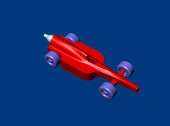
Table of Contents
Introduction to RhinoCAM
Prepare part for machining.
Machining the Bottom Half of the Race Car
Creating the Horizontal Roughing Operation
Create the Machining Operation
Creating the Parallel Finishing Operation
Creating region for restricting tool motions
Creating the Parallel Finish Operation
Simulate Parallel Finishing Operation
Machining the Top Half of the Race Car
Cutting the Part
Setting up to X value of machine zero to cut the bottom half
Setting up to Y value of machine zero to cut the bottom half
Setting up to Z value of machine zero
Applying the tool radius corrections to the X & Y zero values
|
At this point of the tutorial you have created the RaceCar.3DM file and planning to machine this part using RhinoCAM. RhinoCAM is a plug-in that is completely integrated in Rhino and requires Rhino 3.0 to be installed in order for it to run. This plug-in is a machining program that allows the user to create 2-1/2 axis, 3 Axis and hole making operations. |
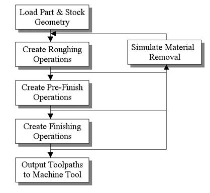
The typical workflow in RhinoCAM is as shown below.
|
|
Once the machining strategy is developed then you will be ready to machine the part
The main user interface for the RhinoCAM plug-in is the RhinoCAM Browser window. This window sprouts all of the buttons and other user interface objects that allow the user to program and create machining operations. This browser is organized to make the machining process easy to use. It consists of 4 tabs, Setup, Tools, Mops (Machining Operations) and Stock. The user sequentially progresses from one tab to the next during the programming process. As each tab is selected a context sensitive toolbar with specific functions appears at the top of the window. These toolbar buttons allow the user to effect specific actions that aid in the programming process. The user progresses from the left most to the right most button in each toolbar during the programming process.
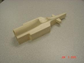
We will machine car by approaching it on two sides, that is, in two setups. The first setup will be to machine the bottom of the car. The second setup will be to machine the top half of the car. The stock used for this tutorial is a wooden block from www.pitsco.com (part # 28886). The stock comes with a hole for the CO2 container.
The steps involved in this process are as follows:
Modify the frame so that a hole can be made at the rear side of the car to place the CO2 canister.
Machine the bottom half of the car (First Setup). This will allow to cut the front wheel axel for the car.
Flip the part and Machine the top half of the car (Second Setup)
In creating programs for each setup, the following steps will be followed:
Set the Machine zero point or Locate geometry with respect to the machine coordinates
Create / Select the tool used for machining
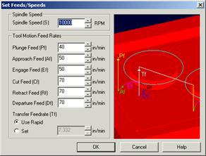
Set the feeds and speeds
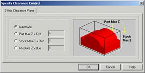
Set the clearance plane for the non-cutting transfer moves of the cutter
Select the machining regions for containing the cutter to specific areas to cut
Select the machine operations and set the parameters
Generate the toolpath
Simulate the toolpath.
You may have to repeat either all or part of these steps for subsequent operations.
|
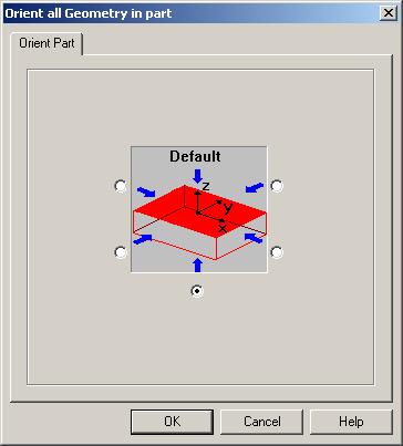
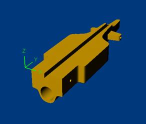
First load the file PitscoCO2RaceCar Use the Orient Geometry button in the RhinoCAM Setup tab toolbar to set the tool axis such that the bottom side of the car is facing upwards |
|
|
The part should be oriented and displayed as shown to the right |
|
|
|
|
|
On the Setup
tab, click Click on the Stock tab at the bottom to see the stock you just created. Note: Once this step is performed the stock model is positioned such that the world coordinate zero is at the lower left corner of the stock model and also aligned with the highest Z face of the stock model. |
|
|
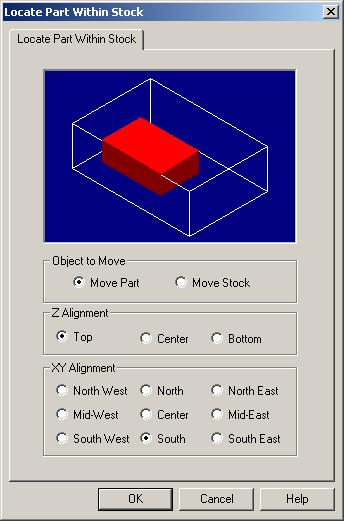
On the Setup
tab, Make sure the Object to Move is set to Move Part. Note: The purpose is to position the part model in relation to the stock model since we have already created the stock model in the correct position. Important: When we load the stock on the machine tool we need to make sure that we locate the machine tool zero at the lower left corner of the stock as well. This is because all the toolpath coordinates that are output to the machine tool by RhinoCAM will be with respect to the world coordinate zero. If the programmed position of the zero and the actual machine tool zero are not coincident then the actual cut part will be positionally inaccurate. |
|
In this setup you will machine the bottom half of the car in two operations:
3 Axis Horizontal Roughing to remove a large amount of stock
In both of these operations we will use the same ball end cutter of 0.25 inches radius.
Now we will create a roughing operation to remove as much material as possible.
|
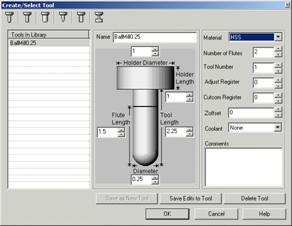
Go to Tools tab, Click on In the Name field, type in BallMill0.25 and choose the Save As New Tool button to save the tool. |
|
|
Exit out of the dialog and select the Tools tab in the Browser window. You should see the created tool appear in the window as shown. You should also see the tool name appear in the Status Bar indicating that the tool has been make active. |
|
|
Go to Tools tab, Click on You will see the following dialog box. Press save to save the tool in the library. You will load this tool later while machining the top side. |
|
|
Go to Mops tab, Click on |
|
|
Go to Mops tab, Click on |
|
|
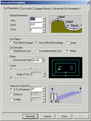
Go to Mops tab, Click on Select the parameters as shown Set intol and outol to 0.01, Stock to 0, cut pattern to part offset, cut direction to climb, start point inside and step over control 25. |
|
|
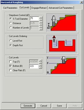
Select the Cut Levels tab and as shown Set Step down control(dZ) to 75 % Tool diameter Cut level ordering to depth first Cut Levels check Bottom (B) and enter (You will limit the cut to half the distance from the top) |
|
|
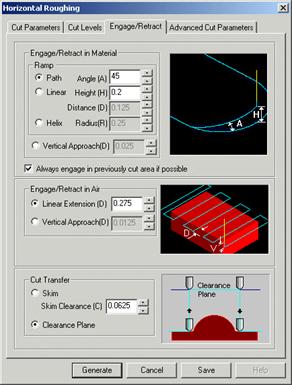
Select the Engage / Retract tab as shown Check Ramp, enter angle(A) = 45, Height(H)= 0.2 Check Always engage in previously cut area if possible) Engage/Retract in air. Select linear extension (D)=0.275 Click on Generate. Please wait it may take few minutes to generate toolpath |
|
|
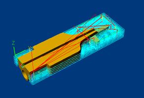
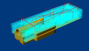
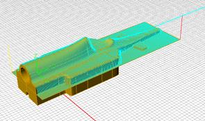
If the Hide Toolpath is unchecked you will see the tool path as shown. |
|
|
Go to Stock tab and press |
|
At this time we will create a toolpath to cleanup the area near the nose since the roughing operation will leave quite a bit of material due to the complex shape near the nose area. We will create a region or closed curve to contain the cutter to the desired area. This is done so that we do not waste tool motions in areas where there is no need to remove any additional material.
|
In the top view create a rectangle that encloses the nose section of the car (as shown) Make sure that this curve has enough space between it and the nose geometry such that the tool can completely machine the nose Using layer manager, assign this curve to a new layer with a Red color |
| |||||
|
Select the created region that was just created. A change in color indicates that the region has been selected. As mentioned above we will restrict the tool motion for the finishing operation to lie inside of this rectangular region. Go to Mops tab, Click on Select the parameters as shown Set intol and outol to , Stock to , cut direction to Mixed Step over control to 15 % tool diameter |
|
|
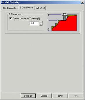
Go to Z containment tab In Z containment check Do not cut below Z value (B) enter value This will restrict the toolpath with the specified Z levels. |
|
|
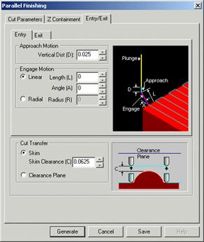
Go to Entry/Exit tab, Approach motion Veritical Distance(D) = 0.025 Engage motion set to Linear and values set to 0 In Cut Transfer, Select skim and set the value to 0.0625. Click on Generate. Please wait it may take few minutes to generate toolpath |
|
|
If the Hide tool path is unchecked and if you are displaying the Top view, you will see the tool path as shown here. |
|
|
Go to Stock tab and press |
|
Now we have completed the programming the bottom half the racecar.
Next you will create the G code file for machining this part
|
Go to Setup tab and
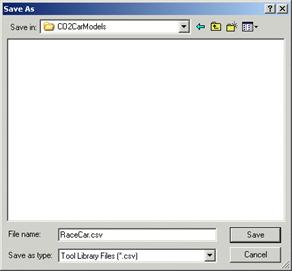
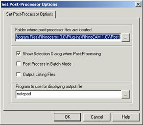
chose The G code file will be displayed in the notepad after creating the post file |
|
|
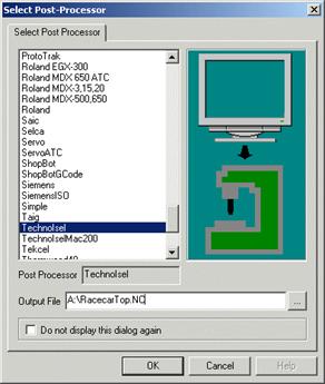
Go to Mops tab and highlight the Machine operations at the top and Right click the mouse button and select Post ALL and choose TechoIsel post processor Enter RaceCarBottom.nc as the output file for G code file. (Chose the correct path where you wish to write to this file) |
|
In this section we will program the toolpaths to machine the top half of the part. On the machine tool you will have to flip the part about the Y axis about 180 degrees to correctly orient the stock model for applying these toolpath.
During programming of the top half, you will repeat most of the steps that were used in machining the bottom half of the car.
You will machine the top half of the car in two operations:
3 Axis Horizontal Roughing using 0.25 inch ball mill
Parallel finishing to perform the finish operation.
|
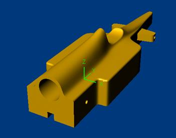
Load the file PitscoCO2RaceCar.3dm The part should come in the correct orientation with the top of the part pointing upwards. Before beginning to program, make sure that the part is oriented as shown here. |
|
|
In the Setup
tab, click Input the coordinates shown in the dialog. Notice that the X coordinate of the origin is set at 2.5. This is done so that the stock model is positioned with its highest right corner coincident with the world coordinate zero point. Click on the Stock tab at the bottom of the Browser window to see the stock created stock displayed in the active view port. Note: Once this step is performed the stock model is positioned such that the world coordinate zero is at the lower right corner of the stock model and also aligned with the highest Z face of the stock model. Also note that this is different from the previous setup where the world coordinate zero was at the lower left corner. This is an important convention to follow. The reasons for doing this is to make sure that the machine tool zero is set about the same vertical edge of the stock model when machining either side of the model. Doing this will minimize errors due to positioning inaccuracies. |
|
|
On the Setup
tab, Make sure the Object to Move is set to Move Part. Set the Z Alignment to Top and the XY Alignment to South as shown in the picture Once this step is completed, the part and stock models are positioned correctly with respect to each other. |
|
|
In the top view create a Rectangular plane Input coordinates First corner (-2.65,0.0,-1.3) Second corner (-0.15,8.75,-1.3) Using layer manager, assign this surface to a new layer with a Red color You will see the surface as shown. You will use this region later on for finishing just the axle area. |
|
|
Go to Tools tab, Click on You will see that the following tools will appear in the browser as shown |
|
|
Go to Mops tab, Click on |
|
|
Go to Mops tab, Click on |
|
This step is creating the roughing operation that will remove most of the material to be machined.
|
Go to Mops tab, Click on Select the parameters as shown Set intol and outol to Stock to , cut pattern to Stock offset, cut direction to Climb, start point inside and step over control |
|
|
Select the Cut Levels tab and as shown Set Step down control(dZ) to 100 % Tool diameter Cut level ordering to depth first Cut Levels check Bottom (B) and enter (You will limit the cut to half the distance from the top ) |
|
|
Select the Engage / Retract tab as shown Check Ramp, enter angle(A) = 45, Height(H)= 0.2 Check Always engage in previously cut area if possible) Engage/Retract in air. Select linear extension (D)=0.275 Click on Generate. Please wait it may take few minutes to generate toolpath |
|
Toolpath Generated.
|
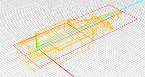
If the Hide tool path is unchecked and if you are in the shaded mode you will see the tool path as shown |
|
|
Go to Stock tab and
press |
|
This step is the finishing operation is intended to provide smooth surface and remove the excess material that is left behind from the previous operation.
|
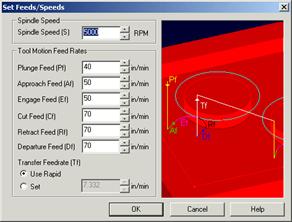
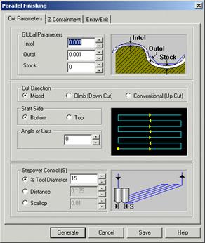
Go to Mops tab, Click on Select the Global parameters as shown Set intol and outol to , Stock to In cut Direction, select Mixed, Start Side Bottom Angle of cuts set to In Step over control, select % of tool diameter and enter Do not check any thing in Z containment tab. |
|
|
Go to Entry / Exit tab. Set Approach motion to 0.025 Select Linear engage motion and enter in both Length (L) and Angle(A) boxes. This will ensure vertical entry In the Exit tab repeat the same values for Retract motion. Select Cut transfer too Skim and enter a value = Click on Generate. Please wait it may take few minutes to generate toolpath |
|
Toolpath Generated.
|
If the Hide tool path is unchecked and if you are in the shaded mode you will see the tool path as shown |
|
|
Go to Stock tab and
press |
|
Save the file as RaceCarForPitscoTop.3dm.
|
Go to Mops tab and highlight the Machine operations at the top and Right click the mouse button and select Post ALL and choose TechoIsel post processor Enter RaceCarTop.nc as the output file for G code file. (Chose the correct path where you wish to write to this file) |
|
Two G code files created for The Techno milling machine and you will use these files to machine the part.
Make sure you read the safety instructions recommended by Techno-Isel and follow them strictly It is important to pay attention to these areas before you start machining.
The steps involved in machining the part are:
Select the correct tool (0.25 inc ball mill) and check for wear and tear. Using the proper wrench fasten the tool firmly at the center of the spindle. Also it is important to make sure the tool is vertical. Check this with a right angle set to the table.
Make sure that the vice that holds the stock is secured firmly and the sides parallel to the X and Y axes are aligned correctly.
Note: To check for the correct Y alignment follow this procedure. Using the tool to touch the sides of the clamp on the two far ends of the vice along the Y axis. Check the Y value reading on the controller software. Both readings should be the same for perfect alignment. If they are not, reorient the vice and repeat the procedure until the alignment is as desired. Recheck the alignment after tightening.
Using a level make sure the stock is horizontal. Also make sure that at least 1.5 inches of the stock should be above the vice jaws to prevent the tool from crashing into the vice.
Secure the stock firmly in the vice so that the stock will not slip from the table while machining. This is an important safety step. Mark the SouthWest vertical edge of the stock so that when you flip the part to machine the top side you will use this edge for setting the machine zero.
Set the machine zero to the same location we have chosen in our machining setup in RhinoCAM (South-West corner for bottom half and South-East corner for Top half). The technique we are going to use to set the zero point correctly is illustrated in pictures below. You will need a small strip of paper for this. Also mark the vertical edge starting at the South-West corner with a marker. We will use this edge as a reference edge to position the zero point when the stock model is flipped over to machine the other side.
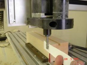
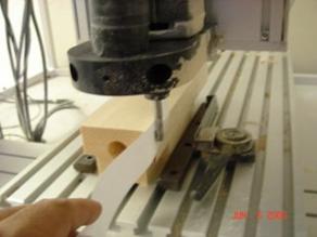
In this step you will setup up the X value of the machine zero to be located such that the tool is touching the left face of the stock model.
|
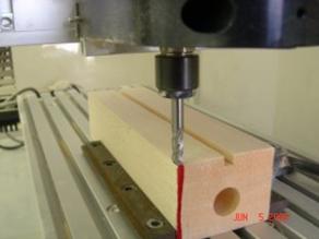
Move the tool in the X direction such that the tool will clear the stock model. Then lower the tool below the top of the stock model. Now jog the tool in the +X direction using the Step mode on the Techno-Isel controller until it is close to the left face. Then insert the strip of paper between the stock model and the tool and continue jogging the tool towards the stock model in small increments. Stop jogging the tool at the first location when the strip of paper cannot be moved freely. This position will be where the tool starts touching the stock model on its left face. Zero the X position of the tool to this location. |
|
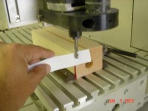
In this step you will setup up the Y value of the machine zero to be located such that the tool is touching the front face of the stock model.
|
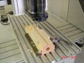
Move the tool in the Y direction such that the tool will clear the stock model and then lower the tool below the top of the stock model. Now jog the tool in the +Y direction using the Step mode on the Techno-Isel controller until it is close to the front face. Then insert the strip of paper between the stock model and the tool and continue jogging the tool towards the stock model in small increments. Stop jogging the tool at the first location when the strip of paper cannot be moved freely. This position will be where the tool starts touching the stock model on its front face. Zero the Y position of the tool to this location. |
|
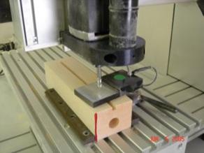
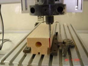
To set the Z zero value we use the electronic touch pad.
|
Place the touch pad on the stock model as shown. Position the tool above the shiny portion of the touch pad. Then select the Tool button on the controller software and select the Touch off Z Zero Position button. This will automatically move the tool down and set the Z value correctly once the tool touches the pad |
|
|
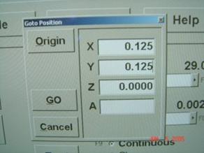
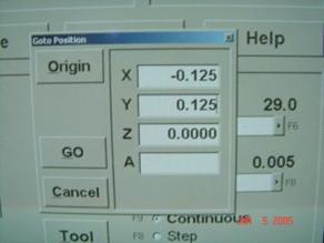
We have now set the X & Y zero values such that the tool is touching the left and front faces of the model. To set the X & Y zero values to be coincident with the South-West corner we will now apply the correction for the tool radius. Move the tool up in Z to make sure it clears the top face of the stock model. Using the Techno-Isel controller software select the GoTo button and specify 0.125 inches in both the X and Y fields as shown and select the Go button. After the machine has stopped moving Zero the machine to this new position. |
|
|
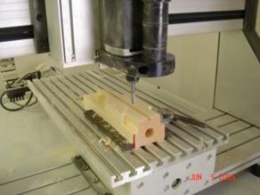
Select the GoTo button and depress the Origin button for a few seconds. The machine should move the tool such that it is positioned as shown here. |
|
|
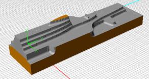
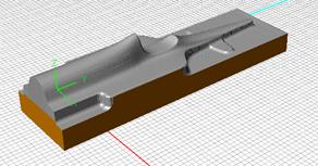
Make sure that the spindle is set to Auto mode on the controller software Using the File button on the controller software, load the BottomHalf.nc. Select the Pre-process button followed by the preview button. Verify that the toolpath looks correct. Select the Start button and select the Resume button when the controller pauses the machine for loading the tool. After roughing operation the bottom half of the part will appear as shown. After the finishing operation the model should look like the one shown here. |
|
Once the bottom half has been machined, flip the stock model about the Y axis and locate it on the vice. Follow these steps similar to setting up for machining the bottom half.
|
First set up the X value of the zero point such that the tool is touching the right side of the stock model. |
|
|||
|
Next set up the Y value of the zero point such that the tool is touching the front face of the stock model. |
|
|||
|
Set up the Z value of the zero point using the touch pad as was done for the bottom side machining. | ||||
|
Apply the tool radius corrections. In this case make sure the corrections are 0.125 inches for X and 0.125 inches for Y as shown. |
|
|||
|
Select the GoTo button and depress the Origin button for a few seconds. The machine should move the tool such that it is positioned as shown here. Notice that the tool is positioned about the same vertical edge. This can be confirmed by the mark on the edge that we had placed earlier. Load the file RaceCarTop.nc and start the machine. |
|
|||
|
After completing the finishing operation of the final machined part should look like the one shown here. Using a fine sand paper, sand the surfaces to smooth the surfaces. You are now ready to add the wheels. |
| |||
Ready to race anyone?
|
Politica de confidentialitate | Termeni si conditii de utilizare |

Vizualizari: 2953
Importanta: ![]()
Termeni si conditii de utilizare | Contact
© SCRIGROUP 2026 . All rights reserved